
Related Manuals for Alcatel-Lucent OA5710V


Summary of Contents for Alcatel-Lucent OA5710V
- Page 1 Manual Alcatel-Lucent Enterprise OA5710V Router Installation Manual Copyright© ALU Dm567-I Version 9.3 9/2017 Alcatel-Lucent Enterprise OA5710V Router...
- Page 2 This publication is subject to change. Alcatel-Lucent Enterprise offers no warranty whatsoever for information contained in this manual. Alcatel-Lucent Enterprise is not liable for any direct, indirect, collateral, consequential or any other damage connec- ted to the delivery, supply or use of this manual.
-
Page 3: Table Of Contents
Chapter 2 OA5710V Router ........3 Features........ - Page 4 Configuration Connector ....... . A.3.8 Power Supply Connector ....... OA5710V Router...
- Page 5 RF GSM/WCDMA Specifications ......WIFI Specifications ........OA5710V Router...
- Page 6 Table of Contents Alcatel-Lucent Enterprise OA5710V Router...
-
Page 7: Chapter 1 About This Manual
1 About This Manual Alcatel-Lucent Enterprise Chapter 1 About This Manual This installation manual for the OA5710V router contains information on how to correctly install this device in a work- ing environment. 1.1 Supported Devices The information provided in this installation manual only applies to the OA5710V router 1.2 Who should read this manual? -
Page 8: Related Documentation
1 About This Manual Alcatel-Lucent Enterprise Latin America 877-919-9526 EMEA +800 00200100 (Toll Free) or +1(650)385-2193 Asia Pacific +65 6240 8484 Web: support.esd.alcatel-lucent.com Email: ebg_global_supportcenter@al-enterprise.com 1.8 Related Documentation ALU Dm741-I ADSL- VDSL2 ALU Dm748-I Software Updating ALU Dm781-I Cellular Interface OA5710V Router... -
Page 9: Chapter 2 Oa5710V Router
2.1.2 Hardware Monitoring The only way to monitor the OA5710V router hardware is through the LEDs panel. The LEDs provide visual informa- tion on the state of the device. They indicate the condition of the hardware components, if there is connectivity, data flow, etc. -
Page 10: Chapter 3 Components And Power Supply
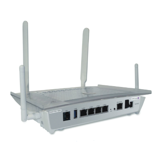
RJ-45 connector, which provides access to the OA5710V local console for config- uring and monitoring purposes. 3.1.2 Rear Panel The following figure shows the rear panel. Here you can see the rest of connectors for the OA5710V router. Rear Panel Fig. 2:... -
Page 11: Side Panels
Two Wi-Fi antennas are located on the side panels, one on either side. Right hand side panel Left hand side panel Fig. 3: and Fig. 4: 3.1.4 Underside Panel The following elements can be found on the underside panel: OA5710V Router... -
Page 12: Top Panel (Leds)
The LEDs panel provides information on the status of the components (whether they are active or not) and on the network activity. LEDs panel Fig. 5: The OA5710V router LEDs are shown in the above figure. The table below contains a description of them. LEDs table Status Description... -
Page 13: Mounting In Rack
Indicates the coverage level the 3G internal module has. 0 level (all LEDs off) to 4 (all LEDs on). (1, 2, 3, 4) 3.2 Mounting in rack The OA5710V router cannot be mounted in a rack. However, there are other types of mounting. OA5710V Router... -
Page 14: Standalone
3 Components and Power Supply Alcatel-Lucent Enterprise 3.2.1 Standalone The OA5710V router can be placed as a standalone on a flat, stable surface. Please ensure there is enough space around the router for ventilation purposes and that the electricity cables can comfortably reach it. - Page 15 3 Components and Power Supply Alcatel-Lucent Enterprise Wall-Mounting Features on the OA5710V Router Fig. 8: Previous Figure shows the wall-mounting features on the OA5710V . Wall screws 10.2 cm (4.02 inches) Chassis mounting holes (on bottom) Router chassis Mounting surface...
-
Page 16: Plug-In Modules
To remove the device, simply remove it from the slot where it was inserted. See Fig. 9 on page 10. 3.4 Power Source The OA5710V router is powered though an external AC/DC. Warning The equipment must be used with the power supply provided by the manufacturer. Workplace Conditions. Main Characteristics •... -
Page 17: Connecting
The router’s default configuration establishes the following IP address and mask: • IP address: 192.168.1.1 • IP mask: 255.255.255.0 Note Some devices leave the factory with customized settings. This personalization can mean that the de- fault configuration may be different from the one shown above. OA5710V Router... -
Page 18: Connecting The Data
During booting and in BIOS mode, the Eth WAN connector is not operative. 3.6.3 DSL Connection The OA5710V has a DSL connector to connect to a VSDL2/ADSL network. This is a 4-wire female RJ11 connector that uses the central pair for data transmission/reception. - Page 19 (PSTN or ISDN) directly connected to the same line. This device ensures the DSL signal does not reach the basic service device, and that undesired signals generated by the device do not interfere with the DSL signal. A typical installation with micro-filters is shown in figure 15. OA5710V Router...
-
Page 20: Wwan Antenna Connection (Cell Connector)
The OA5710V router has three connectors for 3G antennas. To assemble and disassemble the antennas, simply screw them into the connectors labeled Cell (located on the front panel of the router). Installing these antennas in the OA5710V router helps improve the quality of the signal received and transmitted by the cellular model. -
Page 21: Wireless Lan Antenna Connection (Wi-Fi Connectors)
3.6.5 Wireless LAN Antenna Connection (Wi-Fi connectors) The OA5710V router has two RF antenna connectors for an external antenna to improve the quality of the signal re- ceived and transmitted by the Wireless LAN module. This module is internal and can be activated by purchasing the corresponding software license. To assemble and disassemble the antennas provided with the device, just screw them into the connectors, labeled Wi-Fi, which are located on both lateral panels of the router. -
Page 22: Installing The Sim Card
3.7 Installing the SIM card The OA5710V has a Wireless WAN interface that, in order to operate, requires one SIM card to be inserted into the device. Certain services (CDMA) provided by several carriers in some countries do not require SIM cards. -
Page 23: Chapter 4 Compliance
Chapter 4 Compliance 4.1 Manufacturer Information Brand Teldat Manufacturer Teldat S.A. Country Spain Postal Address Isacc Newton, 10 Parque Tecnológico de Madrid, 28760 Tres Cantos, Madid, Spain International Phone +34 91 807 65 65 4.2 Safety Warnings Connecting Disconnect OA5710V Router... - Page 24 4 Compliance Alcatel-Lucent Enterprise OA5710V Router...
- Page 25 4 Compliance Alcatel-Lucent Enterprise OA5710V Router...
- Page 26 4 Compliance Alcatel-Lucent Enterprise OA5710V Router...
-
Page 27: Weee Information
WARNING: This product contains chemicals known to the State of California to cause cancer and birth defects or other reproductive harm. 4.5 China RoHS Teldat products also comply with the requirements set forth in China's Environ- mental Declaration and carry the "EFUP 10" label shown on the left. OA5710V Router... - Page 28 4 Compliance Alcatel-Lucent Enterprise OA5710V Router...
-
Page 29: Ec Declaration Of Conformity
—Directive 2014/53/EU (RED) replaces Directive 1999/5/EC (R&TTE) on 13th June 2016 The EC declaration of conformity and additional product documentation can be accessed here: support.esd.alcatel-lucent.com 4.7 CE Marking This equipment is in conformity with the CE procedures and marking. OA5710V Router... -
Page 30: National Restrictions
In accordance with Article 10 of 2014/53/EU, we inform you that national restrictions and requirements may apply when it comes to authorization. These can evolve with time. Alcatel-Lucent Enterprise recommends that you check with local authorities what the latest status of national regulations is. -
Page 31: Fcc Part 68 Notice
For product available in the USA/Canada market, only channel 1~11 can be operated. Selection of other channels is not possible. Pour les produits disponibles aux États-Unis / Canada du marché, seul le canal 1 à 11 peuvent être exploités. Sélection d'autres canaux n'est pas possible. OA5710V Router... -
Page 32: Ic Radiation Exposure Statement
The Ringer Equivalence Number (REN) is an indication of the maximum number of devices allowed to be connected to a telephone interface. The termination of an interface may consist of any combination of devices subject only to the requirement that the sum of the RENs of all the devices not exceed five. OA5710V Router... - Page 33 à une interface téléphonique. La terminaison d’une interface peut consister en une combinaison quel- conque de dispositifs, à la seule condition que la somme d’indices d’équivalence de la sonnerie de tous les dis- positifs n’excède pas cinq. OA5710V Router...
-
Page 34: Appendix A Technical Information
Check the appropriate license is available for use. A.2 Updating the software The OA5710V router can be updated to new releases. Please contact your distributor for further details on new re- leases. There are various ways to update one of our routers. For further information, please see manual: ALU Dm748-I Soft- ware Updating. -
Page 35: Lan Connector
BI-DB+ BI-DC+ BI-DC- BI-DB- BI-DB- BI-DD+ BI-DD- A.3.2 WAN Connector RJ45 WAN RJ45 PIN FE Signals GE Signals BI-DA+ BI-DA+ BI-DA- BI-DA- BI-DB+ BI-DB+ BI-DC+ BI-DC- BI-DB- BI-DB- BI-DD+ BI-DD- A.3.3 WWAN/Cell Connector (female) Internal RF in/out External OA5710V Router... -
Page 36: Wlan/Wifi Connector (Male)
Technical Information Alcatel-Lucent Enterprise A.3.4 WLAN/WiFi Connector (male) Internal RF in/out External A.3.5 DSL Connector RJ11 DSL RJ11 PIN Line Line A.3.6 USB Connector USB Type A DATA- DATA+ Shell Shield A.3.7 Configuration Connector RJ45 CONFIGURATION RJ45 PIN CONF OA5710V Router... -
Page 37: Power Supply Connector
4 port Switch managed with MDI/MDX auto detection. SPEED 10/100/1000 mbps (BaseT). CONNECTOR RJ45 female. A.4.3 WAN Interface STANDARDS Ethernet (802.3). SPEED 10/100/1000 mbps (BaseT). CONNECTOR RJ45 female. A.4.4 DSL Interface STANDARDS Please see manual Dm741-I. SPEED Please see manual Dm741-I. CONNECTOR RJ11 female. OA5710V Router... -
Page 38: Wireless Wan Interface
2 RF SMA male. A.4.7 USB Interface 3G USB MODEMS Please visit the following website support.esd.alcatel-lucent.com to get a list of the supported 3G USB modems. SPEED The interface complies with the USB 2.0 (480 mbps) standard; the end speed de- pends on the 3G USB modem used. -
Page 39: External Power Supply
LENGTH x WIDTH x HEIGHT 242 x 179 x 48 mm. WEIGHT 0.8 kg. A.4.12 Environmental Specifications TEMPERATURE OPERATING NORMALLY: 0 ºC to 45 ºC STORED: -30 ºC to 85 ºC RELATIVE HUMIDITY On: 5 % to 90 % OA5710V Router... -
Page 40: Appendix B Radio Information
Appendix B Radio Information B.1 RF LTE Specifications The LTE equipment OA5710V-4G provides LTE, DC-HSPA+, HSPA+, HSDPA, HSUPA, WCDMA, GSM, GPRS, EDGE network connectivity over several radio frequency bands, in accordance with 3GPP Standards. This product is supplied with YWX-6221SAX9-508 antennas. To comply with the regulations in force, do not pick oth- er antennas. -
Page 41: Wifi Specifications
802.11n (HT40) @ 5 GHz 2 Channels EIRP - Output Power (dBm) 2.4 GHz (tolerance ± 2 dBm) 802.11b @ 1 Mbps 2412 ~ 2472 MHz: +18 dBm 802.11g @ 6 Mbps 2412 ~ 2472 MHz: +18 dBm OA5710V Router... - Page 42 2412 ~ 2472 MHz: +18 dBm 802.11n (HT40) at MCS0 2422 ~ 2462 MHz: +18 dBm 5 GHz 802.11a @ 6 Mbps 5180 MHz: +21 dBm 802.11n (HT20) at MCS0 5180 MHz: +21 dBm 802.11n (HT40) at MCS0 5190 MHz: +20 dBm OA5710V Router...
Need help?
Do you have a question about the OA5710V and is the answer not in the manual?
Questions and answers