
Related Manuals for Yamaha PW-SE series


Summary of Contents for Yamaha PW-SE series
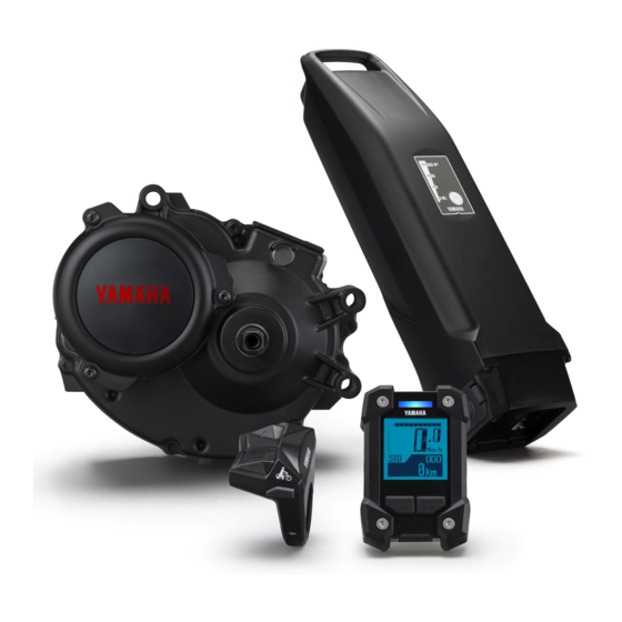
- Page 1 q READ THIS MANUAL CAREFULLY! It contains important safety information. Drive Unit Display Unit Battery Pack Battery Charger ORIGINAL INSTRUCTIONS...
-
Page 3: Table Of Contents
TABLE OF CONTENTS INTRODUCTION ..............1 LOCATION OF THE WARNING AND SPECIFICATION LABELS ................4 DESCRIPTION ..............6 E-BIKE SYSTEMS ...............7 SAFETY INFORMATION ...........10 INSTRUMENT AND CONTROL FUNCTIONS ....13 BATTERY PACK AND CHARGING PROCEDURE ..33 CHECKING THE RESIDUAL BATTERY CAPACITY ..41 PRE-OPERATION CHECK ..........43 CLEANING, MAINTENANCE AND STORAGE ....44 TRANSPORT ..............46 CONSUMER INFORMATION ..........47... -
Page 4: Introduction
INTRODUCTION These original instructions have been prepared for your Drive Unit, display unit, battery pack and battery charger. FAILURE TO FOLLOW THE WARNINGS CONTAINED IN THIS MANUAL CAN RESULT IN SERI- OUS INJURY OR DEATH. Particularly important information is distinguished in this manual by the following notations: This is the safety alert symbol. - Page 5 INTRODUCTION The Bluetooth word mark and logos are registered trademarks owned by the Bluetooth SIG, Inc. ® and any use of such marks by YAMAHA MOTOR CO., LTD. is under license.
- Page 6 Please check your local riding laws and regulations before operating this e-Bike Systems bicycle. Drive Unit, Display Unit, Battery Pack, Battery Charger ORIGINAL INSTRUCTIONS ©2017 by Yamaha Motor Co., Ltd. 1st edition, March 2017 All rights reserved. Any reprinting or unauthorized use without the written permission of Yamaha Motor Co., Ltd.
-
Page 7: Location Of The Warning And Specification Labels
LOCATION OF THE WARNING AND SPECIFICATION LABELS Read and understand all of the labels on your battery pack and battery charger. These labels con- tain important information for safe and proper operation. Never remove any labels from your bat- tery pack and battery charger: Battery pack... - Page 8 LOCATION OF THE WARNING AND SPECIFICATION LABELS Battery charger How to disconnect the plug. 1.GRASP 2.PULL Familiarize yourself with the following pictograms and read the explanatory text, then make sure to check the pictograms that apply to your model. Read the Owner’s manual Do not dispose of in a fire Do not disassemble Do not use with wet hands...
-
Page 9: Description
DESCRIPTION 1. Drive Unit 2. Speed sensor set a) Magnet sensor spoke type b) Pick up 3. Display unit a) Display b) Clamp c) Switch 4. Battery pack (rear carrier type 500 Wh/400 Wh) 5. Battery pack (down tube type 500 Wh/400 Wh) 6. -
Page 10: E-Bike Systems
E-BIKE SYSTEMS The e-Bike Systems are designed to give you the optimal amount of power assist. It assists you within a standard range based on factors such as your pedaling strength, bicycle speed, and current gear. The e-Bike Systems do not assist in the following situations: •... - Page 11 E-BIKE SYSTEMS Multiple power assist modes are available. High High-Performance mode Standard mode Power-saving Eco mode +Eco mode Starting off Level road Inclined road Steep incline * This illustration is for reference purposes only. Actual performance may vary depending on road conditions, wind, and other factors. Use when you want to ride more comfortably, such as when High-Performance mode climbing a steep hill.
- Page 12 E-BIKE SYSTEMS Conditions that could decrease remaining assist distance The remaining assist distance will decrease when riding in the following conditions: • Frequent starts and stops • Numerous steep inclines • Poor road surface conditions • When carrying heavy loads •...
-
Page 13: Safety Information
SAFETY INFORMATION Never use this battery charger to charge other electrical appliances. Do not use any other charger or charging method to recharge the special batter- ies. Using any other charger could result in fire, explosion, or damage the batter- ies. - Page 14 SAFETY INFORMATION Do not use if the battery pack case is damaged, cracked, or if you smell any unu- sual odors. Leaking battery fluid can cause serious injury. Do not short the contacts of the battery pack. Doing so could cause the battery pack to become hot or catch fire, resulting in serious injury or property damage.
- Page 15 SAFETY INFORMATION Do not use the wireless function with Bluetooth low energy technology in areas such as hospitals or medical institutions where use of electronic equipment or wireless equipment is prohibited. Otherwise, this could affect the medical equip- ment, etc. and cause an accident. When using the wireless function with Bluetooth low energy technology, keep the display at a safe distance from heart pacemakers in use.
-
Page 16: Instrument And Control Functions
INSTRUMENT AND CONTROL FUNCTIONS Display unit Assist mode lamp Battery capacity Speedometer Function select switch indicator Assist mode switch (up) Bluetooth indicator Assist power meter Assist mode indicator Function display Assist mode switch (down) Pushing assist switch Power switch Light switch USB receptacle... - Page 17 INSTRUMENT AND CONTROL FUNCTIONS Display unit The display unit offers the following operations and infor- mation displays. 2 Installing the battery The display needs to be removed and installed for chang- ing the battery. • Remove the two bolts on back side of the clamp, and then remove the display.
- Page 18 INSTRUMENT AND CONTROL FUNCTIONS 2 Adjusting the display angle Adjust the display angle by loosening the clamp bolt. The angle depends on each rider. After adjustment, tighten the clamp bolt. WARNING Tighten the clamp bolt to 3.0–4.5 N·m. During riding, vibration could cause the clamp bolt to come loose with the risk that the clamp may fall off.
- Page 19 INSTRUMENT AND CONTROL FUNCTIONS 2 Displaying and switching the assist mode You can select the assist mode by using the assist mode Assist mode indicator Assist mode lamp switches (up & down). The selected assist mode is displayed by the assist mode indicator and assist mode lamp color.
- Page 20 INSTRUMENT AND CONTROL FUNCTIONS 2 Speedometer The speedometer displays your bicycle speed (in kilome- ter per hour or mile per hour). To select the km/mile, see “Stopwatch and settings”. Speedometer If your bicycle speed is less than 2.0 km/h or 1.2 MPH, the speedometer displays “0.0 km/h or 0.0 MPH”.
- Page 21 INSTRUMENT AND CONTROL FUNCTIONS 2 Function display The function display can display the following functions. • Odometer • Trip meter • Average bicycle speed • Maximum bicycle speed • Remaining assist distance • Battery capacity (%) • Cadence • Clock Function display Push the function select switch, the display changes as fol- lows:...
- Page 22 INSTRUMENT AND CONTROL FUNCTIONS 7 Maximum bicycle speed This displays the maximum bicycle speed (in kilometers per hour or miles per hour) since it was last reset. When you turn off the power, the data up to that point will remain in the display.
- Page 23 INSTRUMENT AND CONTROL FUNCTIONS 2 Headlight “On/Off” (Applies only to models equipped with a headlight powered by the battery pack. The taillight, which is powered by the battery pack, is switched on/off with the headlight.) Each time you press the light switch, the headlight switch- es between “On”...
- Page 24 INSTRUMENT AND CONTROL FUNCTIONS 2 Stopwatch and settings The display enables the following. • STOPWATCH Stopwatch function • TIME ADJ (TIME ADJUST) Clock setting • DIST UNIT (DISTANCE UNIT) km/mile setting • DSPL ITEM (DISPLAY ITEM) Sets the items to be displayed in the function display during normal riding.
- Page 25 INSTRUMENT AND CONTROL FUNCTIONS 7 STOPWATCH The stopwatch counts time in seconds up to a maximum of 9 hours 59 minutes 59 seconds. If this maximum is reached, it will automatically start over from 0 (zero) and continue counting. • TIME MEASUREMENT Use the function select switch to start and stop time measurement.
- Page 26 INSTRUMENT AND CONTROL FUNCTIONS 7 TIME ADJ (TIME ADJUST) You can adjust the time of the clock. 1. Check that the “Hour” is flashing and adjust the hour by using the assist mode switches (up & down). 2. Press the function select switch to adjust the minutes. 3.
- Page 27 INSTRUMENT AND CONTROL FUNCTIONS 7 DIST UNIT (DISTANCE UNIT) You can select the display units for distance and speed. When “km” is selected, the travelled distance will be indi- cated in kilometers and the speed in km/h. When “mile” is selected, the travelled distance will be indi- cated in miles and the speed in mph.
- Page 28 INSTRUMENT AND CONTROL FUNCTIONS 7 DSPL ITEM (DISPLAY ITEM) You can select to show or hide different items in the func- tion display during normal riding. The items which you can select to show or hide are: TRIP (trip meter), AVE (average bicycle speed), MAX (maxi- mum bicycle speed), DIST (remaining assist distance), BATTERY (battery capacity (%)), CADENCE (cadence), and TIME (clock).
- Page 29 INSTRUMENT AND CONTROL FUNCTIONS 7 RESET You can reset the TRIP (trip meter), AVE (average bicycle speed), and MAX (maximum bicycle speed) values. You cannot reset the odometer. 1. Select an item by using the assist mode switches (up & down) and use the function select switch to place a check mark in the check box for the item that you want to reset.
- Page 30 INSTRUMENT AND CONTROL FUNCTIONS 7 BLE (Bluetooth low energy technology) You can set the profile to use the wireless function with Bluetooth low energy technology, or you can select not to use the wireless function. When “CSCP” is selected, the Cycling Speed and Ca- dence Profile will be available.
- Page 31 INSTRUMENT AND CONTROL FUNCTIONS 7 USB You can select the USB receptacle as a power supply re- ceptacle or as a receptacle for communication over a wired connection. When “PWR SPLY” is selected, it can be used as a power supply receptacle.
- Page 32 INSTRUMENT AND CONTROL FUNCTIONS 7 LED Assist mode lamp You can select to light up the assist mode lamp according to the assist mode or keep the assist mode lamp unlit all the time. When “ON” is selected, the assist mode lamp will light up according to the assist mode.
- Page 33 INSTRUMENT AND CONTROL FUNCTIONS 2 Pushing assist When you are on or off the bicycle and start moving it, you can use pushing assist without pedaling the bicycle. To use pushing assist, press and hold the pushing assist switch. Pushing assist will stop in the following situations: •...
- Page 34 INSTRUMENT AND CONTROL FUNCTIONS 2 Power supply to external devices Power can be supplied to most external devices (e.g. vari- ous smart phones etc.) by connecting a commercial USB 2.0 OTG cable. [To supply power] 1. Open the USB receptacle cap of the display. 2.
- Page 35 For more information, see the instruction manual of the wireless communication equipment. * “####” of “Yamaha ####” is a combination of irregular al- phanumeric characters. • Keep the distance between the display and wireless communication equipment within 1 m. The maximum communication distance of this equipment is 1 m.
-
Page 36: Battery Pack And Charging Procedure
• Its performance decreases in extremely hot or cold en- vironments. • It naturally loses its charge. Charger The battery pack for the Yamaha e-Bike Systems also has display Battery Battery capacity an embedded computer which notifies you of estimated... - Page 37 BATTERY PACK AND CHARGING PROCEDURE Appropriate charging environments For safe and efficient charging, use the battery charger in a location that is: • Flat and stable (when on the bicycle) • Free of rain or moisture • Out of direct sunlight •...
- Page 38 BATTERY PACK AND CHARGING PROCEDURE WARNING If a charging fault occurs during charging, remove the power plug of the battery charger from the socket and wait for the battery pack/battery charger to cool. [CHARGING THE BATTERY PACK MOUNTED ON THE BICYCLE] (Rear carrier type) 1.
- Page 39 BATTERY PACK AND CHARGING PROCEDURE 3. See “Reading the charging status”, and check that the battery charger is charging the battery pack. Lock-release ring 4. The battery capacity indicator lamps will light up one by one until all four are on. Then, when charging is com- plete, all of the lamps will go off.
- Page 40 BATTERY PACK AND CHARGING PROCEDURE NOTICE • Do not connect the charging plug of the battery charger with the charging connector of the battery in a wet state. • Be sure to connect the charging plug only after the charging connector on the battery pack is com- pletely dry.
- Page 41 BATTERY PACK AND CHARGING PROCEDURE Top of the case Battery pack mounting method (down tube type) Battery bottom • Insert the battery in the direction of the arrow so that the battery bottom is aligned to the top of the case. •...
- Page 42 BATTERY PACK AND CHARGING PROCEDURE Reading the charging status Battery capacity indicator lamps Battery Current Details charger lamp status (Rear carrier type) (Down tube type) Lit power lamps indicate the amount of charging completed. A flashing power lamp indicates current progress. During charging, the Charging battery capacity indicator...
- Page 43 BATTERY PACK AND CHARGING PROCEDURE For example, even if normal charging is started, if the battery temperature or the surrounding tem- perature is too high or too low, the charging may be extended or charging may be stopped without the battery being charged sufficiently in order to protect the battery. Charging time guidelines Although charging time varies depending on residual bat- Charging...
-
Page 44: Checking The Residual Battery Capacity
CHECKING THE RESIDUAL BATTERY CAPACITY You can check the estimate of how much capacity is left in the battery and to what extent it is charged. The check can be performed using either the display unit’s residual battery capacity indi- cator or the battery’s residual battery capacity indicator lamps. - Page 45 CHECKING THE RESIDUAL BATTERY CAPACITY Display of the battery capacity indicator lamps and the estimate of the residual battery capacity When checking the residual battery capacity, push the battery capacity indicator button “ ”. Display of the battery capacity Estimate of indicator lamps the residual Applicable situation...
-
Page 46: Pre-Operation Check
PRE-OPERATION CHECK WARNING Be sure to perform the inspection before riding the bicycle. If there is anything you do not understand or find difficult, please consult a bicycle dealer. NOTICE • If you confirm there is a fault, have your bicycle inspected at a dealer as soon as possi- ble. -
Page 47: Cleaning, Maintenance And Storage
CLEANING, MAINTENANCE AND STORAGE NOTICE Do not use high-pressure washers or steam jet clean- ers since they can cause water seepage, resulting in property damage or malfunction of the Drive Unit or display unit or battery pack. Should water get inside one of these units, have an authorized dealer inspect your bicycle. - Page 48 CLEANING, MAINTENANCE AND STORAGE Long storage period (1 month or longer) and using it again after a long storage period • When storing the bicycle for a long period (1 month or longer), remove the battery pack and store it using the following procedure.
-
Page 49: Transport
TRANSPORT The batteries are subject to the Dangerous Goods Legislation requirements. When being transport- ed by third parties (e.g. via air transport or forwarding agency), special requirements on packaging and labels must be observed. To prepare the item for shipping, consult a hazardous materials ex- pert. -
Page 50: Consumer Information
CONSUMER INFORMATION Disposal The Drive Unit, battery pack, battery charger, display unit, speed sensor set, accessories and packaging should be sorted for environmental-friendly recycling. Do not dispose of the bicycle or its components as house- hold waste. For EU countries: According to the European Guideline 2012/19/EU, electri- cal devices/tools that are no longer usable, and according to the European Guideline 2006/66/EC, defective or used... -
Page 51: Troubleshooting
TROUBLESHOOTING E-Bike Systems Symptom Check Action Press the power switch on the display Is the display unit’s power on? unit to turn the power on. Is the battery pack Install a charged battery pack. installed? Is the battery pack Charge the battery pack. charged? Has the bicycle remained stationary for... - Page 52 TROUBLESHOOTING Symptom Check Action The assist mode lamp lights up in red, the main riding display and “ER” are displayed alternately, and an error description is indicated in the function display. The problem occurs in the e-Bike Systems. Turn off the power and then turn it on again.
- Page 53 TROUBLESHOOTING Symptom Check Action An assist mode lamp lights up in red and an error description is indicated in the function display. The speed sensor cannot detect a correct signal. Turn off the power to the display unit and then turn it on again. Select the assist mode and then ride for a short distance.
- Page 54 TROUBLESHOOTING Power supply of external devices via USB connection Symptom Check Action Press the power switch on the display Is the display unit’s power on? unit to turn the power on. Is the USB version Use an external device that complies correct? with USB 2.0.
- Page 55 TROUBLESHOOTING Battery pack and charger Symptom Check Action Is the power plug Reconnect and try charging firmly connected? Is again. If the battery pack still does not the charging plug charge, the battery charger might firmly inserted in the battery pack? be malfunctioning.
- Page 56 TROUBLESHOOTING Symptom Check Action Both side lamps are flashing simultaneously. The battery pack protection (Rear carrier type) (Down tube type) feature has been activated and the system cannot be used. Replace the battery pack at an authorized dealer as soon as possible.
-
Page 57: Specifications
SPECIFICATIONS Range of assist speed 0 to less than 25 km/h Type Brushless DC type Electric motor Rated output 250 W Control method depends on Assist power control method pedaling torque and bicycle speed PASB2/PASB5 Type (Lithium-ion battery) Rear carrier battery Voltage 36 V 500 Wh/400 Wh... - Page 58 • YAMAHA MOTOR CO., LTD. can not be held liable in any way for damages or other loss result- ing from information leaks during the communication via Bluetooth low energy technology.
Need help?
Do you have a question about the PW-SE series and is the answer not in the manual?
Questions and answers