Table of Contents
Advertisement
Quick Links
Advertisement
Table of Contents

Related Manuals for Speco O2iBD2


Summary of Contents for Speco O2iBD2
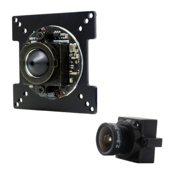
- Page 1 O2iBD2 ® Intensifier IP Full HD Megapixel Board IP Camera...
- Page 2 ’ ’ Directions Be careful not to cause any physical damage by dropping or throwing the camera. Especially keep the device out of reach from children. Do not disassemble the camera. No after service is assumed when disassembled. Use only power adapters compatible with the unit. Be careful to prevent moisture or water penetration into the unit.
- Page 3 ’ ’ Revision History Date Revision Details 10/1/2015 First manual revision creation. Rev.1.0 (Oct. 2015)
-
Page 4: Table Of Contents
Functional Description ............................11 Installation Notes ..............................13 Getting Started ............................... 13 4.1. PC Requirement ..............................13 4.1.1. Connect PC and O2iBD2 to network......................14 4.1.2. Set IP parameters on O2iBD2 ........................14 4.1.3. Remote video connection to O2iBD2 ...................... 15 4.1.4. -
Page 5: Introduction
It enables real time transmission of synchronized video of Full HD resolution and audio data. Remote clients can connect to ONSIP O2iBD2 for the real time video/audio data through various client solutions running on PC, PDA or mobile phones. Real time 2-way communication is available through bidirectional audio communication feature. -
Page 6: Specifications
’ ’ 1.2. Specifications Camera Image sensor Progressive scan 1/3 inch CMOS 2M pixels Full resolution 1,920 x 1,080 pixels (Full HD) Sync System Internal Lens 2.9mm fixed, 3.6mm fixed pinhole Day & Night AUTO, DAY, NIGHT Back Light Compensation ON / OFF White Balance ATW(2.000K ~ 10,000K) / MANUAL / PUSH... - Page 7 Network Protocol - RTP, RTSP, SDP, HTTP, SMTP, FTP, DHCP, UPnP - NTP, DNS, DynDNS Dynamic IP Speco DDNS (free of charge) - User ID & Password protection, IP address filtering Security - Digest Authentication, User Access Log - RTSP streaming with proprietary format for control information...
-
Page 8: Product Description
’ 2. Product Description 2.1. Contents The product package contains the following contains the following: Contents Description Remarks Remarks O2iBD2 O2iBD2 main and camera units Screws (1 type) Screws (1 type) Anchors (1 type) Anchors (1 type) Accessories L-type wrench... -
Page 9: Physical Description
’ ’ 2.3. Physical description 2.3.1. External View Figure 2-1. External view of O2iBD2 2.3.2. Dimensions Figure 2-2. Dimensions... -
Page 10: Front And Rear View Of Main Unit
’ ’ 2.3.3. Front and Rear view of Main Unit Cable bracket screw hole Description Line Output Ground MIC/Line Input MIC/Line Input Figure 2-3. Front view Relay Output Relay Output Relay Output Relay Output Sensor Input (-) Sensor Input ( Sensor Input (+) Sensor Input (+) Connect... -
Page 11: Functional Description
Power : Power input for supplying 12V DC V DC power. Caution : If O2iBD2 is powered by PoE, do not plug in DC Jack with active DC power is powered by PoE, do not plug in DC Jack with active DC power into DC is powered by PoE, do not plug in DC Jack with active DC power power connector. - Page 12 ’ ’ Sensor Input Connect external alarm sensor. Examples of sensing devices are infrared sensor, motion sensor, heat/smoke sensor, magnetic sensor, etc. Connect the two wires of the sensors to “Sensor Input”. The sensor type (NC/NO) can be set in admin page. Multiple sensor devices can be connected in parallel. NO/NC Type Open Collector Type Photo Coupler...
-
Page 13: Installation Notes
Brief information for initial operation of O2iBD2 is provided in this chapter. 4.1. PC Requirement Audio/Video streaming data received from O2iBD2 can be displayed or stored in a PC running client programs. Minimum requirement of the PC is described below:... -
Page 14: Connect Pc And O2Ibd2 To Network
(PC is needed to assign IP address to O2iBD2) 2. In the case of using PoE, connect the PC and O2iBD2 to the network using one of the following ways. If your LAN Switch does not support standard PoE, connect O2iBD2 as shown in dotted line in Figure. The DC power is applied through DC adapter. -
Page 15: Remote Video Connection To O2Ibd2
1. Connection through Web Viewer Web Viewer offers simplest way of video connection to Web Viewer offers simplest way of video connection to O2iBD2. For video connection, enter the IP address of . For video connection, enter the IP address of... - Page 16 ’ ’ Connection to Admin Page Connection to Admin Page Basic Control Figure 4-3. Web Viewer admin”, Default ID and password of Admin Page are “admin “1234”. Guide”. For more detailed information, please refer to the For more detailed information, please refer to the “Configuration...
-
Page 17: Additional Settings Through Connection To The Admin Page
’ ’ 4.1.4. Additional settings through connection to the Admin Page All parameters of the camera are factory default out of the box. For a more sophisticated target application, parameters need to be changed through the admin page. The admin page can be connected through “http://IP_Address:Port_Number/admin.htm”... -
Page 18: Troubleshooting
’ ’ 5. Troubleshooting 5.1. No power is applied In case of Standard PoE (Power over Ethernet) Power supply through standard PoE is possible only when the following conditions are met. 1. Standard PoE is supported on the product. 2. The LAN switch supports standard PoE. Make sure that both the IP camera and the LAN switch support standard PoE (IEEE 802.3af) In case of DC adapter If PoE is not applied, the power and network connection should be made through separate cables. -
Page 19: Cannot Connect To The Video
’ ’ 5.2. Cannot connect to the Video Check the status of the network connection through PING test. Try the following on your PC : Start > Run > Cmd > Ping IP address (Ex : Ping 172.16.42.51) If “Reply from ~” message is returned (① in the figure below), the network connection is in normal state. Try connection to the video again. -
Page 20: Technical Assistance
’ ’ 5.3. Technical Assistance If you need any technical assistance, please contact If you need any technical assistance, please contact technical support. For immediate service please provide the . For immediate service please provide the following information. Model name 1 . -
Page 21: Appendix A - Important Notice In Exchanging Sd Card (Micro Sd)
’ ’ Appendix A – Important Notice in Exchanging SD Card (Micro SD) SD Card is a non-volatile memory device for storing video and audio data on the product. Note that continuous recording to the SD Card will cause the memory cell to wear out, eventually resulting in failure. When you plug out the SD Card for replacement or other purpose, follow the steps below in order to prevent data loss or crash of the SD Card.
Need help?
Do you have a question about the O2iBD2 and is the answer not in the manual?
Questions and answers