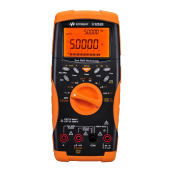
Keysight U1251B Quick Start Manual
Hide thumbs
Also See for U1251B:
- User's and service manual (198 pages) ,
- Quick start manuals (178 pages) ,
- User and service manual (173 pages)
Table of Contents
Advertisement
Quick Links
Download this manual
See also:
User and Service Manual
Advertisement
Table of Contents

Subscribe to Our Youtube Channel
Summary of Contents for Keysight U1251B
-
Page 1: Digital Multimeter
Keysight U1251B and U1252B Handheld Digital Multimeter Quick Start Guide... - Page 2 Do not proceed beyond a WARNING notice until the indicated conditions are fully understood and met. For further safety information details, refer to the Keysight U1251B and U1252B Handheld Digital Multimeter User’s Guide. Keysight U1251B and U1252B Quick Start Guide...
-
Page 3: Table Of Contents
Measurements ..... . . 17 Square Wave Output (for U1252B only) ..19 Keysight U1251B and U1252B Quick Start Guide... - Page 4 THIS PAGE HAS BEEN INTENTIONALLY LEFT BLANK. Keysight U1251B and U1252B Quick Start Guide...
- Page 5 4 Alligator clips 4 Printed Quick Start Guide 4 Certificate of Calibration 4 9 V alkaline battery (for U1251B only) 4 Rechargeable 8.4 V battery (for U1252B only) 4 Power cord and AC adapter (for U1252B only) If anything is missing or damaged, please contact the nearest Keysight Sales Office.
-
Page 6: Charging The Battery
DC power supply in order to set the 24 V DC output and the over current limitation to a value more than 0.5 A. Ensure that the polarity of the connection is correct. Keysight U1251B and U1252B Quick Start Guide... - Page 7 The multimeter may indicate that charging is complete after ten minutes when charging a new rechargeable battery. This is a normal phenomenon with rechargeable batteries. Remove the rechargeable battery from the device, reinsert it, and repeat the charging procedure. Keysight U1251B and U1252B Quick Start Guide...
-
Page 8: Functions And Features
Press and hold for > 1 s. Views the logged data Press for > 1 s, press scroll through the logged data. Clears the logged data Press for > 1 s, press for >1 s. Keysight U1251B and U1252B Quick Start Guide... -
Page 9: Input Terminals And Overload Protection
1000 V R.M.S Diode 1000 V R.M.S < 0.3 A short circuit Resistance current Capacitance Temperature Current (μA and mA) µA.mA 440 mA/1000 V 30 kA/fast-acting fuse Current (A) 11 A/1000 V 30 kA/fast-acting fuse Keysight U1251B and U1252B Quick Start Guide... -
Page 10: Performing Voltage Measurements
2 Connect the red and black test leads to input terminals V. mV (red) and COM (black) respectively. 3 Probe the test points and read the display. 4 Press to display dual measurements. Parameter can be switched consecutively. Keysight U1251B and U1252B Quick Start Guide... - Page 11 To avoid possible electric shock or personal injury, CAUTION enable the Filter to verify the presence of hazardous DC voltages. Displayed DC voltages can be influenced by high frequency AC components and must be filtered to assure an accurate reading. Keysight U1251B and U1252B Quick Start Guide...
-
Page 12: Performing Current Measurements
2 Connect the red and black test leads to input terminals µA.mA (red) and COM (black) or A (blue) and COM (black) respectively. 3 Probe the test points in series with the circuit and read the display. Keysight U1251B and U1252B Quick Start Guide... - Page 13 µA.mA (red) and COM (black). – If the current is > 440 mA, connect the red and black test leads to input terminals A (red) and COM (black). Keysight U1251B and U1252B Quick Start Guide...
-
Page 14: Performing Resistance, Conductance, And Continuity Measurements
Ω (red) and COM (black) respectively. 3 Probe the test points (by shunting the resistor) and read the display. 4 Press to scroll through audible continuity, conductance, and resistance tests as shown. Keysight U1251B and U1252B Quick Start Guide... -
Page 15: Performing Capacitance And Temperature Measurements
2 Connect the red and black test leads to input terminals (red) and COM (black) respectively. 3 Connect the red test lead to the positive terminal of the capacitor, and the black test lead to the negative terminal. 4 Read the display. Keysight U1251B and U1252B Quick Start Guide... - Page 16 2 Plug the thermocouple adapter (with the thermocouple probe connected to it) into input terminals (red) and COM (black). 3 Touch the measurement surface with the thermocouple probe. 4 Read the display. Keysight U1251B and U1252B Quick Start Guide...
-
Page 17: Frequency And Frequency Counter Measurements
1. This accommodates for higher frequency range of up to 985 kHz. 3 Connect the red and black test leads to input terminals V (red) and COM (black) respectively. Keysight U1251B and U1252B Quick Start Guide... - Page 18 Never use the frequency counter on AC power line systems. – For input more than 30 Vpp, you are required to use frequency measurement mode available under the current or voltage measurement instead of frequency counter. Keysight U1251B and U1252B Quick Start Guide...
-
Page 19: Square Wave Output (For U1252B Only)
Duty cycle can be set for 256 steps and each step is 0.390625%. The display only indicates the best resolution with 0.001%. Pressing is the same as pressing NOTE Keysight U1251B and U1252B Quick Start Guide... - Page 20 THIS PAGE HAS BEEN INTENTIONALLY LEFT BLANK. Keysight U1251B and U1252B Quick Start Guide...
- Page 21 This information is subject to change without notice. Always refer to the Keysight website for the latest revision. © Keysight Technologies 2009-2017 Edition 7, June 1, 2017 Printed in Malaysia *U1251-90046* U1251-90046 www.keysight.com...


Need help?
Do you have a question about the U1251B and is the answer not in the manual?
Questions and answers