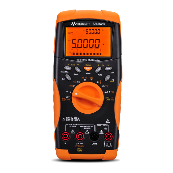
Keysight U1251B User's And Service Manual
Handheld digital multimeter
Hide thumbs
Also See for U1251B:
- Quick start manuals (178 pages) ,
- User and service manual (173 pages) ,
- Quick start manual (21 pages)
Table of Contents
Advertisement
Quick Links
Advertisement
Table of Contents

Subscribe to Our Youtube Channel
Related Manuals for Keysight U1251B


Summary of Contents for Keysight U1251B
- Page 1 Keysight U1251B and U1252B Handheld Digital Multimeter User’s and Service Guide...
- Page 3 Keysight U1251B/U1252B User’s and Service Guide...
- Page 4 5301 Stevens Creek Blvd. any information contained herein. Santa Clara, CA 95051 USA Should Keysight and the user have a separate written agreement with WA R N I N G warranty terms covering the material...
-
Page 5: Safety Symbols
In position of a bi-stable push control CAT III Equipotentiality Category III 1000 V overvoltage protection 1000 V Equipment protected throughout by CAT IV double insulation or reinforced Category IV 600 V overvoltage protection 600 V insulation Keysight U1251B/U1252B User’s and Service Guide... -
Page 6: Safety Information
Keysight Technologies assumes no liability for the customer’s failure to comply with these requirements. • Turn off the circuit power and discharge all high-voltage capacitors in the circuit before C A U T I O N you perform resistance, continuity, diodes, or capacitance tests. - Page 7 • Inspect the test probes for damaged insulation or exposed metal, and check for continuity. Do not use the test probe if it is damaged. • Do not use any other AC charger adaptor apart from the one certified by Keysight with this product.
- Page 8 Cet appareil ISM est confomre a la this electrical/electronic product in norme NMB-001 du Canada. domestic household waste. The CSA mark is a registered trademark of the Canadian Standards Association. Keysight U1251B/U1252B User’s and Service Guide...
- Page 9 To return this unwanted instrument, contact your nearest Keysight Technologies, or visit: www.keysight.com/environment/product more information. Keysight Technologies, through Rechargeable Battery Recycling Corporation (RBRC), offers free and convenient battery recycling options in the U.S. and Canada. Contact RBRC at 877-2-RECYCLE (877.273.2925) or online at: http://www.call2recycle.org/ for the nearest recycling location.
-
Page 10: In This Guide
In This Guide… Getting Started This chapter contains information on the Keysight U1251B and U1252B handheld multimeter front panel, rotary switch, keypad, display, terminals and rear panel. Making Measurements This chapter contains information on how to make measurements using the U1251B and U1252B handheld digital multimeter. - Page 11 Web site. You can search the DoC by its product model or description. http://www.keysight.com/go/conformity If you are unable to search for the respective DoC, please contact your N O T E local Keysight representative. Keysight U1251B/U1252B User’s and Service Guide...
- Page 12 THIS PAGE HAS BEEN INTENTIONALLY LEFT BLANK. Keysight U1251B/U1252B User’s and Service Guide...
-
Page 13: Table Of Contents
Contents Getting Started Introducing the U1251B/U1252B Handheld Digital Multimeter Check the shipment Adjusting the tilt-stand The front panel at a glance The rear panel at a glance The rotary switch at a glance The keypad at a glance The display at a glance... - Page 14 Square Wave Output (for U1252B) Remote Communication Changing The Default Setting Selecting Setup Mode Setting Data Hold/Refresh Hold Mode Setting Data Logging Mode Setting Thermocouple Types (U1252B only) Setting Reference Impedance for dBm Measurement Keysight U1251B/U1252B User’s and Service Guide...
- Page 15 Returning to Default Factory Settings Setting the Battery Voltage Setting the Filter Maintenance Introduction General maintenance Battery replacement Storage considerations Charging the battery Fuse checking procedure Replacing the fuse Troubleshooting Replaceable Parts To order replaceable parts Keysight U1251B/U1252B User’s and Service Guide XIII...
- Page 16 Calibration Process Using the front panel for adjustments Adjustments Consideration Valid adjustment input values Adjustment Procedure Finishing the Adjustment To Read the Calibration Count Calibration Errors Specifications Product Characteristics Measurement Category Measurement category definition Keysight U1251B/U1252B User’s and Service Guide...
- Page 17 Temperature Specifications Frequency Specifications Duty Cycle and Pulse Width Specifications Frequency Sensitivity Specifications Peak Hold Specifications Frequency Counter Specifications for U1252B Square Wave Output for U1252B Operating Specifications Display update rate (approximate) Input impedance Keysight U1251B/U1252B User’s and Service Guide...
- Page 18 THIS PAGE HAS BEEN INTENTIONALLY LEFT BLANK. Keysight U1251B/U1252B User’s and Service Guide...
- Page 19 Figure 3-3 Refresh hold mode operation Figure 3-4 Null (relative) mode operation 58 Figure 3-5 dBm/dBV display mode operation 60 Figure 3-6 1 ms peak hold mode operation 62 Figure 3-7 Hand (Manual) logging mode operation 64 Keysight U1251B/U1252B User’s and Service Guide XVII...
- Page 20 Figure 5-6 Battery charging procedure 111 Figure 5-7 Fuse checking procedures 112 Figure 5-8 Fuse replacement 115 Figure 6-1 LCD display 123 Figure 6-2 Input warning 124 Figure 6-3 Charge terminal alert 125 XVIII Keysight U1251B/U1252B User’s and Service Guide...
- Page 21 Table 7-1 DC Accuracy ± (% of reading + Number of Least Signifi- cant Digit) 158 Table 7-2 U1251B accuracy specifications ± (% of reading + num- ber of LSD) for true RMS AC voltage 161 Table 7-3 U1251B accuracy specifications ± (% of reading + num- ber of LSD) for true RMS AC current 161 Table 7-4 U1252B accuracy specifications ±...
- Page 22 Table 7-15 Frequency counter (divide by 1) specifications 168 Table 7-16 Frequency counter (divide by 100 specifications 169 Table 7-17 Square wave output specifications 169 Table 7-18 Display update rate (approximate) 171 Table 7-19 Input Impedance 172 Keysight U1251B/U1252B User’s and Service Guide...
- Page 23 Selecting display with the Dual button 17 Selecting display with the Shift button 20 The terminals at a glance 22 This chapter contains information on the Keysight U1251B and U1252B handheld multimeter front panel, rotary switch, keypad, display, terminals and rear panel.
-
Page 24: Introducing The U1251B/U1252B Handheld Digital Multimeter
• Ambient temperature on second display • Battery capacity indicator • Bright orange LED backlight • Resistance measurement of up to 50 MΩ (for U1251B) and 500 MΩ (for U1252B) • Conductance measurement from 0.01 nS (100 GΩ) 50 nS •... -
Page 25: Check The Shipment
• Power cord & AC adapter (U1252B only) • Quick Start Guide • Certificate of Calibration Contact your nearest Keysight Sales Office if any of the above are missing. Inspect the shipping containing for damage. Signs of damage may include a dented or torn shipping container or cushioning material that indicates signs of unusual stress or compacting. -
Page 26: Adjusting The Tilt-Stand
IR-USB cable To PC (host) Tilt-stand at 30 º ° Figure 1-2 Tilt-stand at 30 Keysight U1251B/U1252B User’s and Service Guide... -
Page 27: Figure 1-3 Tilt-Stand At Hanging Position
3. Flip the tilt-stand over until this side of the stand is facing the multimeter as 4. Re-attach the tilt-stand to an upright position opposed to facing you Figure 1-3 Tilt-stand at hanging position Keysight U1251B/U1252B User’s and Service Guide... -
Page 28: The Front Panel At A Glance
Getting Started Tutorial The front panel at a glance Display Keypad Rotary Switch Terminal Connectors Figure 1-4 U1252B front panel Keysight U1251B/U1252B User’s and Service Guide... -
Page 29: The Rear Panel At A Glance
Getting Started Tutorial The rear panel at a glance IR Communication Port Test probe holders Tilt-stand Battery access cover Figure 1-5 Rear panel Keysight U1251B/U1252B User’s and Service Guide... -
Page 30: The Rotary Switch At A Glance
Capacitance or Temperature DC µA, AC µA, AC+DC µA DC mA, DC current, AC mA, AC current or AC+DC current Square-wave output, Duty cycle, or Pulse width output (for U1252B) and OFF (for U1251B) Keysight U1251B/U1252B User’s and Service Guide... -
Page 31: The Keypad At A Glance
Press to view first or last logged data respectively. Press to scroll up or down logged data. Press for more than 1 second to exit mode. Keysight U1251B/U1252B User’s and Service Guide... - Page 32 For pulse and duty cycle measurement, press to switch trigger slope to positive or negative. When meter is in peak or dynamic-recording mode, press to restart 1 ms peak hold or dynamic recording mode. Keysight U1251B/U1252B User’s and Service Guide...
-
Page 33: The Display At A Glance
3 To set the rotary switch at square wave out position, press only the Dual, Range and Hold buttons or turn the rotary switch to another position. (U1252B only) The LCD signs are explained in the following tables. Figure 1-8 Display symbols Keysight U1251B/U1252B User’s and Service Guide... -
Page 34: Table 1-3 General Display Symbols
Dynamic Recording mode: Minimum value on primary display Dynamic Recording mode: Average value on primary display 1 ms Peak Hold mode: Positive peak value on primary display 1 ms Peak Hold mode: Negative peak value on primary display Keysight U1251B/U1252B User’s and Service Guide... -
Page 35: Table 1-4 Primary Display Symbols
Duty cycle measurement Pulse width unit µmnF Capacitance units: nF, µF, mF ºC Celsius temperature unit ºF Fahrenheit temperature unit Percentage scale readout proportional to DC 0–20 mA Percentage scale readout proportional to DC 4–20 mA Keysight U1251B/U1252B User’s and Service Guide... -
Page 36: Table 1-5 Secondary Display Symbols
When 4–20 mA% scale or 0–20 mA% scale is indicated on the primary display, the bar graph represents the current value and not the percentage value. Keysight U1251B/U1252B User’s and Service Guide... -
Page 37: Selecting Display With The Hz Button
Press access the frequency measurement mode for current or voltage measurements — voltage or current on the secondary Keysight U1251B/U1252B User’s and Service Guide... -
Page 38: Table 1-7 Selecting Display With The Hz Button
Pulse width (ms) DC mV Duty cycle (%) Frequency (Hz) (AC + DC voltage) Pulse width (ms) AC + DC mV Duty cycle (%) Frequency (Hz) (AC Current) Pulse width (ms) AC µA Duty cycle (%) Keysight U1251B/U1252B User’s and Service Guide... -
Page 39: Selecting Display With The Dual Button
100 [for U1252B] Selecting display with the Dual button Press to select different combinations of dual display.Normal single display resumes after you press and hold for more than 1 second. See Table 1- 8 below. Keysight U1251B/U1252B User’s and Service Guide... -
Page 40: Table 1-8 Selecting Display With The Dual Button
Notes for selecting display with the Dual button: 1 Reading of dBm or dBV depends on the last review on AC V. If the last review is dBV, the following display will also remain in dBV. Keysight U1251B/U1252B User’s and Service Guide... - Page 41 [for U1252B] AC + DC mA DC mA Ambient temperature °C or °F AC + DC mA DC A Hz (DC coupling) (DC current) DC A AC A Ambient temperature °C or °F DC A Keysight U1251B/U1252B User’s and Service Guide...
-
Page 42: Selecting Display With The Shift Button
AC V [1][2] dBm (in dual display mode) (AC Voltage) [1][2] dBV (in dual display mode) DC V for U1251B DC V for U1252B AC V (AC + DC Voltage) AC + DC V Keysight U1251B/U1252B User’s and Service Guide... - Page 43 (Square wave output for U1252B) Notes for selecting display with the Shift button: Press to switch between dBm and dBV measurement. Press for more than 1 second to return to AC V measurement only. Keysight U1251B/U1252B User’s and Service Guide...
-
Page 44: The Terminals At A Glance
1000 V R.M.S. for short circuit <0.3 A Ω μA . mA 440 mA / 1000 V 30 kA fast-acting fuse 11 A / 1000 V 30 kA fast-acting fuse for U1252B 440 mA / 1000 V fast-acting fuse Keysight U1251B/U1252B User’s and Service Guide... -
Page 45: Making Measurements
Keysight U1251B and U1252B Handheld Digital Multimeter User’s and Service Guide Making Measurements Understanding The Measurement Instructions 24 Measuring Voltage 24 Measuring AC voltage 25 Measuring DC voltage 26 Measuring AC and DC Signals (U1252B only) 27 µA & mA measurement 28... -
Page 46: Understanding The Measurement Instructions
Probe the test points Read the results on the display Measuring Voltage The U1251B and U1252B offer true- RMS readings for AC measurements that are accurate for sine waves, square waves, triangle waves, staircase waves, and other waveforms without any DC offset. -
Page 47: Measuring Ac Voltage
See Table 1-8 N O T E “Selecting display with the Dual button” on page 17 for a list of the different combinations available on the secondary display. Keysight U1251B/U1252B User’s and Service Guide... -
Page 48: Measuring Dc Voltage
• To avoid possible electric shock or personal injury, enable the Low Pass Filter to verify the presence of hazardous DC voltages. Displayed DC voltage values can be influenced by high frequency AC components and must be filtered to assure an accurate reading. Keysight U1251B/U1252B User’s and Service Guide... -
Page 49: Measuring Ac And Dc Signals (U1252B Only)
DC voltage range equal to or higher than the AC range. This procedure improves the accuracy of the DC measurement by ensuring that the input protection circuits are not activated. Keysight U1251B/U1252B User’s and Service Guide... -
Page 50: Measuring Current
• For A (ampere) measurement, set the rotary switch to and connect the positive test lead to A. • Press to display dual measurements. See Table 1-8 “Selecting display with the Dual button” on page 17 for a list of dual measurements available. Keysight U1251B/U1252B User’s and Service Guide... -
Page 51: Figure 2-3 Measuring Ma And Ma Current
Making Measurements 2 Black Lead Red Lead Figure 2-3 Measuring μA and mA current Keysight U1251B/U1252B User’s and Service Guide... -
Page 52: Percentage Scale Of 4 Ma To 20 Ma
• The percentage scale for 4 mA to 20 mA or 0 mA to 20 mA is calculated using its corresponding DC mA measurement. The U1251B and U1252B will automatically optimize the best resolution according to Table 2-2 below. -
Page 53: Figure 2-4 Measuring Scale Of 4-20 Ma
Making Measurements 2 Black Lead Red Lead Figure 2-4 Measuring scale of 4-20 mA Keysight U1251B/U1252B User’s and Service Guide... -
Page 54: A (Ampere) Measurement
N O T E respectively. The meter is set to A measurement automatically when the red test lead is plugged into the A terminal. Black Lead Red Lead Figure 2-5 A (ampere) current measurement Keysight U1251B/U1252B User’s and Service Guide... -
Page 55: Frequency Counter
• The signal is out of range if the reading is still unstable after the above step. • While the secondary display shows “-1-“, you may scroll through the pulse width (ms), duty cycle (%) and frequency (Hz) measurements by pressing Keysight U1251B/U1252B User’s and Service Guide... -
Page 56: Figure 2-6 Measuring Frequency
2 Making Measurements Black Lead Red Lead Figure 2-6 Measuring frequency Keysight U1251B/U1252B User’s and Service Guide... -
Page 57: Measuring Resistance, Conductance And Testing Continuity
Set up the multimeter to measure resistance as shown in Figure 2- 7. Then probe the test points (by shunting the resistor) and read the display. Black Lead Red Lead Figure 2-7 Measuring resistance Keysight U1251B/U1252B User’s and Service Guide... -
Page 58: Figure 2-8 Audible Continuity, Conductance, And Resistance
2 Making Measurements Press to scroll through audible continuity, conductance and resistance tests as shown in Figure 2- Press Audible continuity Press Press Figure 2-8 Audible continuity, conductance, and resistance test. Keysight U1251B/U1252B User’s and Service Guide... -
Page 59: Table 2-3 Audible Continuity Measurement Range
100 GΩ. As the high- resistance readings are susceptible to noise, you can capture the average readings by using the Dynamic Recording mode. Refer to the section “Dynamic Recording” on page 52 for more information. Keysight U1251B/U1252B User’s and Service Guide... -
Page 60: Figure 2-9 Conductance Measurement
2 Making Measurements Black Lead Red Lead Figure 2-9 Conductance measurement Keysight U1251B/U1252B User’s and Service Guide... -
Page 61: Testing Diodes
• The diode is considered shorted if the meter displays approximately 0 V in both forward and reverse bias modes, and the meter beeps continuously. • The diode is considered open if the meter displays “OL” in both forward and reverse bias modes. Keysight U1251B/U1252B User’s and Service Guide... -
Page 62: Figure 2-10 Measuring Forward Bias Of Diode
2 Making Measurements Black Lead Red Lead Figure 2-10 Measuring forward bias of diode Keysight U1251B/U1252B User’s and Service Guide... -
Page 63: Figure 2-11 Measuring Reverse Bias Of Diode
Making Measurements 2 Black Lead Red Lead Figure 2-11 Measuring reverse bias of diode Keysight U1251B/U1252B User’s and Service Guide... -
Page 64: Measuring Capacitance
Set up the multimeter as shown in Figure 2- 12. Use the red probe lead on the positive terminal of the capacitor and the black probe lead on the negative terminal and read the display. Keysight U1251B/U1252B User’s and Service Guide... -
Page 65: Figure 2-12 Capacitance Measurements
Making Measurements 2 Red Lead Black Lead Figure 2-12 Capacitance measurements Keysight U1251B/U1252B User’s and Service Guide... -
Page 66: Measuring Temperature
6 When measuring above the ambient temperature, move the thermocouple along the surface until you get the highest temperature reading. 7 When measuring below ambient temperature, move the thermocouple along the surface until you get the lowest temperature reading. Keysight U1251B/U1252B User’s and Service Guide... -
Page 67: Figure 2-13 Connecting The Thermal Probe Into The Non-Compensation Transfer Adapater
The 0 °C compensation adapter assists in measuring the relative temperature immediately. Figure 2-13 Connecting the thermal probe into the non-compensation transfer adapater Figure 2-14 Connecting the probe with adapter into the multimeter Keysight U1251B/U1252B User’s and Service Guide... - Page 68 3 After a constant reading is obtained, press to set the reading as the relative reference temperature. 4 Touch the measurement surface with the thermocouple probe. 5 Read the display for the relative temperature. Keysight U1251B/U1252B User’s and Service Guide...
-
Page 69: Figure 2-15 Surface Temperature Measurement
Making Measurements 2 Figure 2-15 Surface temperature measurement Keysight U1251B/U1252B User’s and Service Guide... -
Page 70: Alerts And Warning During Measurement
The primary display indicates a flashing “A- Err” until the test lead is removed from the A input terminal. Refer to Figure 2- Figure 2-16 Input terminal warning Keysight U1251B/U1252B User’s and Service Guide... -
Page 71: Charge Terminal Alert
The primary display indicates a flashing “Ch.Err” until the lead is removed from the input terminal. Refer to Figure 2- 17 below. Figure 2-17 Charge terminal alert Keysight U1251B/U1252B User’s and Service Guide... - Page 72 2 Making Measurements THIS PAGE HAS BEEN INTENTIONALLY LEFT BLANK. Keysight U1251B/U1252B User’s and Service Guide...
-
Page 73: Functions And Features
Data Logging 63 Manual logging 63 Interval logging 65 Reviewing logged data 67 Square Wave Output (for U1252B) 69 Remote Communication 73 This chapter contains information on the functions and features that are available for the U1251B and U1252B digital multimeter. -
Page 74: Dynamic Recording
• The average value is the true average of all the measured values taken in the Dynamic Recording mode. If an overload is recorded, the averaging function will stop and the average value becomes "OL"(overload). is disabled in Dynamic Recording mode. Keysight U1251B/U1252B User’s and Service Guide... -
Page 75: Figure 3-1 Dynamic Recording Mode Operation
Press Max Min for > 1 sec or press for > 1 sec Press Max Min Press Max Min for > 1 sec or press for > 1 sec Figure 3-1 Dynamic recording mode operation Keysight U1251B/U1252B User’s and Service Guide... -
Page 76: Data Hold (Trigger Hold)
3 Press and hold for more than 1 second to quit the data hold function. Press Press Measurement update Press press for > 1 sec. Figure 3-2 Data hold mode operation Keysight U1251B/U1252B User’s and Service Guide... -
Page 77: Refresh Hold
The symbol will remain on and the multimeter will emit a tone to remind you of this. 4 Press again to quit the Refresh Hold function. Keysight U1251B/U1252B User’s and Service Guide... -
Page 78: Figure 3-3 Refresh Hold Mode Operation
• For resistance and diode measurements, the holding value will not be updated if the reading is in “OL” (open state). • The holding value may not be updated when the reading does not reach a stable state for all measurements. Keysight U1251B/U1252B User’s and Service Guide... -
Page 79: Null (Relative)
• When taking a DC voltage measurement, the thermal effect will influence the accuracy. Short the test leads and press Null once the displayed value is stable in order to zero out the display. Keysight U1251B/U1252B User’s and Service Guide... -
Page 80: Figure 3-4 Null (Relative) Mode Operation
Features and Functions Press Press Auto-return after 3 seconds Flash Press as NULL is flashing on the display Figure 3-4 Null (relative) mode operation Keysight U1251B/U1252B User’s and Service Guide... -
Page 81: Decibel Display
The dBm or the dBV measurements can be selected at the ACV position. The selection will be the reference for other voltage measurements. 2 Press for more than 1 second to exit this mode. Keysight U1251B/U1252B User’s and Service Guide... -
Page 82: Figure 3-5 Dbm/Dbv Display Mode Operation
Press for > 1 sec. Press for > 1 sec. Press Press Press for > 1 sec. Only when rotary switch is at Press position Press Press Press Figure 3-5 dBm/dBV display mode operation Keysight U1251B/U1252B User’s and Service Guide... -
Page 83: Ms Peak Hold
• If you need to re-start the peak recording, press 3 Press and hold for more than 1 second to exit this mode. 4 According to the measurements shown in Table 3- 6 on page 62, the crest Factor will be 2.5048/1.768 =1.416. Keysight U1251B/U1252B User’s and Service Guide... -
Page 84: Figure 3-6 1 Ms Peak Hold Mode Operation
Features and Functions Press for > 1 sec. Press Start to capture Start to capture Press Press Press Figure 3-6 1 ms peak hold mode operation Keysight U1251B/U1252B User’s and Service Guide... -
Page 85: Data Logging
To use the data logging function, you will need to connect the multimeter N O T E to a PC using the U1173A IR-to-USB cable (purchased separately) and download the data logging software from Keysight’s website. Please go to: http://www.keysight.com/find/hhTechLib to download the software. -
Page 86: Figure 3-7 Hand (Manual) Logging Mode Operation
The maximum data that can be stored is 100 entries. When the 100 entries N O T E are filled, the secondary display indicates “FULL”, as shown in Figure 3-8. Press for > 1 sec. Auto-return after 3 seconds Figure 3-8 Full Log Keysight U1251B/U1252B User’s and Service Guide... -
Page 87: Interval Logging
“FULL” is indicated on the secondary display. 2 Press for more than 1 second to exit this mode. When interval (automatic) logging is enabled, all keypad operations are N O T E disabled, except for the Log function. Keysight U1251B/U1252B User’s and Service Guide... -
Page 88: Figure 3-9 Interval (Automatic) Logging Mode Operation
Features and Functions Press for > 1 sec. First interval Press for > 1 sec. Press Last interval for > 1 sec. Last +1 interval Stop logging Figure 3-9 Interval (Automatic) logging mode operation Keysight U1251B/U1252B User’s and Service Guide... -
Page 89: Reviewing Logged Data
5 Press for more than 1 second to exit mode. 6 During the data review in either manual or interval logging mode, press for more than one second to clear all the logged values. Keysight U1251B/U1252B User’s and Service Guide... -
Page 90: Figure 3-10 Log Review Mode Operation
Press View Press Press Press Log to clear all Press Log to clear all for > 1 sec manual logs for > 1 sec interval logs Press View Figure 3-10 Log review mode operation Keysight U1251B/U1252B User’s and Service Guide... -
Page 91: Square Wave Output (For U1252B)
(%) on the primary display. 4 Press to adjust the duty cycle. Duty cycle can be set for 256 steps and each step is 0.390625%. The display only indicates the best resolution with 0.001%. Keysight U1251B/U1252B User’s and Service Guide... -
Page 92: Figure 3-11 Frequency Adjustment For Square Wave Output
6 Press to adjust the pulse width. The pulse width can be set for 256 steps and each step is 1/ (256 x Frequency). The display range automatically adjusts in the range of 9.9999~9999.9 ms. Keysight U1251B/U1252B User’s and Service Guide... -
Page 93: Figure 3-12 Duty Cycle Adjustment For Square Wave Output
Features and Functions Press Press Press Press Figure 3-12 Duty cycle adjustment for square wave output Keysight U1251B/U1252B User’s and Service Guide... -
Page 94: Figure 3-13 Pulse Width Adjustment For Square Wave Output
Features and Functions Press Press Press Press Figure 3-13 Pulse width adjustment for square wave output Keysight U1251B/U1252B User’s and Service Guide... -
Page 95: Remote Communication
Keysight Web site. For details on performing PC to meter remote communication click on Help after launching the Keysight GUI Data Logger Software or refer to the GUI Data Logger Quick Start Guide (U1251- 90023) for more information. - Page 96 Features and Functions THIS PAGE HAS BEEN INTENTIONALLY LEFT BLANK. Keysight U1251B/U1252B User’s and Service Guide...
- Page 97 Setting Print Mode 96 Returning to Default Factory Settings 97 Setting the Battery Voltage 98 Setting the Filter 99 This chapter shows you how to change the default factory settings of the U1251B and U1252B and other available setting options.
-
Page 98: Changing The Default Setting
1, “Available setting options in Setup mode,” for details of available options. 3 Press to save changes. These parameters will remain in the non- volatile memory. 4 Press for more than 1 second to exit Setup mode. Keysight U1251B/U1252B User’s and Service Guide... -
Page 99: Table 4-1 Available Setting Options In Setup Mode
Parity check tion (remote control with PC) Sets the baud rate for 2400 Hz, 4800 Hz, 9600 the remote communi- bAUd 9600 Hz Baud rate Hz, 19200 Hz cation (remote control with PC) Keysight U1251B/U1252B User’s and Service Guide... - Page 100 Sets the thermocouple tYPE type to K-type t.CoUP tYPE Thermocouple Sets the thermocouple tYPE type to J-type Enables manual data Hand logging d-LoG Hand Data logging Sets the interval for 1–9999 s automatic data logging Keysight U1251B/U1252B User’s and Service Guide...
- Page 101 2 For b-Lit, APF, rEF and d-LoG menu items, the user can select the digit to be adjusted by pressing 3 This menu option is only available for the U1252B. 4 To view the tEMP menu item, press for more than 1 second. Keysight U1251B/U1252B User’s and Service Guide...
-
Page 102: Setting Data Hold/Refresh Hold Mode
Refresh Hold mode (auto trigger). When the variation of the measuring value exceeds the setting of the variation count, the Refresh Hold will be ready to trigger. Press Press Press Press Press Figure 4-1 Data hold/Refresh hold setup Keysight U1251B/U1252B User’s and Service Guide... -
Page 103: Setting Data Logging Mode
3 Press and hold for more than 1 second to switch between manual and interval data logging setup. Press Press Press Press set interval > 1 second Press Press Figure 4-2 Data logging setup Keysight U1251B/U1252B User’s and Service Guide... -
Page 104: Setting Thermocouple Types (U1252B Only)
Setting Thermocouple Types (U1252B only) The thermocouple sensor types that can be selected are type K (default) or type J. Press to switch between the J and the K type. Press Figure 4-3 Thermocouple type setup Keysight U1251B/U1252B User’s and Service Guide... -
Page 105: Setting Reference Impedance For Dbm Measurement
Setting Reference Impedance for dBm Measurement The reference impedance can be set from 1 to 9999 W. The default value is 50 W. Press Press Press Press Figure 4-4 Reference impedance for dBm measurement setup Keysight U1251B/U1252B User’s and Service Guide... -
Page 106: Setting Minimum Frequency Measurement
The minimum frequency setup influences the measuring rates for frequency, duty cycle and pulse width. The typical measuring rate is based on the minimum frequency of 1 Hz. Press Press Press Press Press Figure 4-5 Minimum frequency setup Keysight U1251B/U1252B User’s and Service Guide... -
Page 107: Setting Temperature Unit
• Celsius- Fahrenheit (d- CF) and Fahrenheit- Celsius (d- FC) dual display setting. Primary-Secondary Display can be swapped by pressing N O T E • Fahrenheit only (°F on primary display) single display setting. Keysight U1251B/U1252B User’s and Service Guide... -
Page 108: Figure 4-6 Temperature Unit Setup
Changing The Default Setting Press Press Press Press Press Figure 4-6 Temperature unit setup Keysight U1251B/U1252B User’s and Service Guide... -
Page 109: Setting Auto Power Saving Mode
• To activate the meter after it has “auto powered- off”, turn the rotary switch to the OFF position. Then turn it back on again. • will be shown on the display during subsequent measurements. Keysight U1251B/U1252B User’s and Service Guide... -
Page 110: Figure 4-7 Auto Power Saving Setup
Changing The Default Setting Press Press Press Press Press Figure 4-7 Auto power saving setup Keysight U1251B/U1252B User’s and Service Guide... -
Page 111: Setting Percentage (%) Scale Readout
(%) scale readout — 4–20 mA or 0–20 mA as proportional to 0~100%. The 25% scale readout represents DC 8 mA at 4–20 mA and DC 5 mA at 0–20 mA. Press Figure 4-8 % scale readout setup Keysight U1251B/U1252B User’s and Service Guide... -
Page 112: Setting Beep Frequency
Changing The Default Setting Setting Beep Frequency The driving frequency can be set to 2400, 1200, 600, or 300Hz. “OFF” disables the beep. Press Press Press Press Press Press Figure 4-9 Beep frequency setup Keysight U1251B/U1252B User’s and Service Guide... -
Page 113: Setting Backlight Timer
• The timer can be set to 1—99 seconds. The backlight will turn off automatically after the set period. • “0FF” disables turning off backlit automatically. Press Press Press Press Press Figure 4-10 Backlit timer setup Keysight U1251B/U1252B User’s and Service Guide... -
Page 114: Setting Baud Rate
Changing The Default Setting Setting Baud Rate Select the baud rate for remote control. The available settings are 2400, 4800, 9600, and 19200 Hz. Press Press Press Press Press Figure 4-11 Baud rate setup remote control Keysight U1251B/U1252B User’s and Service Guide... -
Page 115: Setting Parity Check
Changing The Default Setting Setting Parity Check Select the parity check for remote control. It can be set to none, even, or odd bit. Press Press Press Press Figure 4-12 Parity check setup Keysight U1251B/U1252B User’s and Service Guide... -
Page 116: Setting Data Bit
Changing The Default Setting Setting Data Bit Select the data bit for remote control. It can be set to either 8 or 7 bits. Press Figure 4-13 Data bit setup for remote control Keysight U1251B/U1252B User’s and Service Guide... -
Page 117: Setting Echo Mode
• Echo ON enables the return of characters to the PC in remote communication. • Echo OFF disables the return of characters to the PC. Press Figure 4-14 Echo mode setup for remote control Keysight U1251B/U1252B User’s and Service Guide... -
Page 118: Setting Print Mode
In this mode, the meter automatically sends the newest data to the host continuously but does not accept any commands from the host. flashes during the Print operation. Press Figure 4-15 Print mode setup for remote control Keysight U1251B/U1252B User’s and Service Guide... -
Page 119: Returning To Default Factory Settings
Temperature setting. • The Reset menu item automatically reverts to Refresh Hold menu item after reset has taken place. Press for > 1 sec. Figure 4-16 Reset setup Keysight U1251B/U1252B User’s and Service Guide... -
Page 120: Setting The Battery Voltage
Changing The Default Setting Setting the Battery Voltage Battery type for the multimeter can be set to either 7.2 V or 8.4 V. Press Figure 4-17 Battery voltage selection Keysight U1251B/U1252B User’s and Service Guide... -
Page 121: Setting The Filter
DC voltage measurement. • During AC or Hz measurement (on primary or secondary display), DC filter will be automatically disabled. • For firmware version 2.17 and below, the Filter function is switched off by default. Keysight U1251B/U1252B User’s and Service Guide... -
Page 122: Table 4-2 Filter Defaults
Changing The Default Setting Table 4-2 Filter defaults Parameter Firmware version Default setting 2.17 and below FiLtEr 2.18 and above [1] Firmware is factory-installed and not field-upgradeable. Keysight U1251B/U1252B User’s and Service Guide... -
Page 123: Maintenance
Keysight U1251B and U1252B Handheld Digital Multimeter User’s and Service Guide Maintenance Introduction 102 General maintenance 102 Battery replacement 102 Storage considerations 104 Charging the battery 105 Fuse checking procedure 112 Replacing the fuse 114 Troubleshooting 116 Replaceable Parts 117... -
Page 124: Introduction
If your meter has the rechargeable battery type, refer to the section “Charging the battery” on page 105. The steps for battery replacement are the next page: Keysight U1251B/U1252B User’s and Service Guide... - Page 125 3 Lift the battery cover up. 4 Replace the specified battery. 5 Reverse the above steps to close the cover. List of compatible batteries for the Keysight U1251B : N O T E • 9 V Alkaline non-chargeable battery (ANSI/NEDA 1604A or IEC 6LR61) •...
-
Page 126: Storage Considerations
Maintenance List of compatible batteries for the Keysight U1252B : N O T E • 9 V size 300 mAH Ni-MH rechargeable battery, 7.2 V nominal voltage • 9 V size 250 mAH Ni-MH rechargeable battery, 8.4 V nominal voltage •... -
Page 127: Charging The Battery
To discharge, simply run the multimeter under the battery's power until it shuts down or the low battery warning appears. Keysight U1251B/U1252B User’s and Service Guide... -
Page 128: Table 5-1 Battery Voltage And Corresponding Percentage Of Charges In Standby And Charging Modes
Table 5-1 Battery voltage and corresponding percentage of charges in standby and charging modes Condition Battery voltage Proportional percentage Trickle (SBY) 7.0 V to 9.6 V 0% to 100% Charging 7.2 V to 10.0 V 0% to 100% Keysight U1251B/U1252B User’s and Service Guide... -
Page 129: Figure 5-2 Battery Capacity Display As Trickle
The self- test takes about 2 to 3 minutes. Avoid pressing any button during the self- test. A message is diplayed as shown in Figure 5- Keysight U1251B/U1252B User’s and Service Guide... -
Page 130: Figure 5-3 Self-Test
Maintenance Figure 5-3 Self-test Table 5-2 Error messages Error Error message 1 No battery inside 2 Faulty battery 3 Battery is fully charged Error Error message Keysight U1251B/U1252B User’s and Service Guide... - Page 131 220 minutes. The secondary display will count down the charging time. During charging, no buttons can be pressed. The error message may appear during charging to alert the user of any overcharging of the battery. Keysight U1251B/U1252B User’s and Service Guide...
-
Page 132: Figure 5-4 Charging Mode
8 Remove the DC adapter when the C–End message appears on the secondary display. Do not turn the rotary switch before removing the adapter from the terminals. Figure 5-5 Charge end and trickle state Keysight U1251B/U1252B User’s and Service Guide... -
Page 133: Figure 5-6 Battery Charging Procedure
Maintenance Press to start charge Error-Full Error Error Error-Empty Battery can be charged Fully charged Figure 5-6 Battery charging procedure Keysight U1251B/U1252B User’s and Service Guide... -
Page 134: Fuse Checking Procedure
Refer to Figure 5- 8 for the respective positions of Fuse 1 and Fuse 2. 1 Set the rotary switch to 2 Connect the red test lead to the input terminal Figure 5-7 Fuse checking procedures Keysight U1251B/U1252B User’s and Service Guide... -
Page 135: Table 5-3 Measurement Readings For Fuse Checking
6 Replace the fuse when OL is displayed. Table 5-3 Measurement readings for fuse checking Fuse OK (approximately) Replace fuse Current input terminal Fuse Fuse rating Displayed readings 440 mA/1000 V 6.2 MΩ 0.06 Ω 11 A/1000 V Keysight U1251B/U1252B User’s and Service Guide... -
Page 136: Replacing The Fuse
OFF position. 9 Then re- fasten the circuit board and the bottom cover. 10 Refer to the table below for the part number, rate, and size of the fuses. Keysight U1251B/U1252B User’s and Service Guide... -
Page 137: Figure 5-8 Fuse Replacement
Table 5-4 Fuse specifications Fuse Keysight part number Rating Size Type 2110-1400 440mA/1000V 10 mm x 35 mm Fast blow Fuse 2110-1402 11A/1000V 10 mm x 38 mm Fuse 1 Fuse 2 Figure 5-8 Fuse replacement Keysight U1251B/U1252B User’s and Service Guide... -
Page 138: Troubleshooting
• Check the baud rate, parity, Data bit, Stop bit (default is 9600, n, 8, 1) • Driver install for IR-USB. Notes for basic troubleshooting procedures table: 1 Never turn the rotary switch of the multimeter from the OFF position when it is charging. Keysight U1251B/U1252B User’s and Service Guide... -
Page 139: Replaceable Parts
To order replaceable parts from Keysight, do the following: 1 Contact your nearest Keysight Sales Office or Service Center. 2 Identify the parts by the Keysight part number shown in the support parts list. 3 Provide the instrument model number and serial number. - Page 140 Maintenance THIS PAGE HAS BEEN INTENTIONALLY LEFT BLANK. Keysight U1251B/U1252B User’s and Service Guide...
- Page 141 Keysight U1251B and U1252B Handheld Digital Multimeter User’s and Service Guide Performance Tests and Calibration Calibration Overview 120 Closed-case electronic calibration 120 Keysight Technologies calibration services 120 Calibration interval 121 Adjustment is recommended 121 Recommended Test Equipment 122 Basic Operating Test 123...
-
Page 142: Performance Tests And Calibration
The nonvolatile EEPROM calibration memory is retained even when the power is switched off. Keysight Technologies calibration services When your instrument is due for calibration, contact your local Keysight Service Center to enquire about recalibration services. Keysight U1251B/U1252B User’s and Service Guide... -
Page 143: Calibration Interval
Keysight recommends that readjustment should be performed during the calibration process for best performance. This will ensure that the U1251B/U1252B will remain within the specifications for the next calibration interval. This criterion for the re- adjustment provides the best long–term stability. -
Page 144: Recommended Test Equipment
If the exact instrument is not available, substitute calibration standards of equivalent accuracy. A suggested alternative method would be to use the Keysight 3458A 8½ – Digit Digital Multimeter to measure less accurate yet stable sources. The output value measured from the source can be entered into the instrument as the target calibration value. -
Page 145: Basic Operating Test
ON and OFF. Testing the display Press the Hold button and turn on the meter to view all segments of the display. Compare the display with the example in Table 6- Figure 6-1 LCD display Keysight U1251B/U1252B User’s and Service Guide... -
Page 146: Current Terminal Test
2. The primary display will keep flash- ing unless the test lead is removed from “A” terminal. Before conducting this test, make sure the beep function is not disabled in N O T E setup. Figure 6-2 Input warning Keysight U1251B/U1252B User’s and Service Guide... -
Page 147: Charge Terminal Alert Test
“Ch.Err” until the lead is removed from the terminal. Figure 6-3 Charge terminal alert Before conducting this test, make sure the beep function is not disabled at N O T E setup. Keysight U1251B/U1252B User’s and Service Guide... -
Page 148: Test Considerations
• Ensure that the ambient relative humidity is less than 80%. • Allow a warm- up period of five minutes. • Use shielded twisted pair PTFE- insulated cables to reduce settling and noise errors. Keep the input cables as short as possible. Keysight U1251B/U1252B User’s and Service Guide... -
Page 149: Calibration Security
N O T E can only be changed from the front panel after the instrument has been unsecured. “To unsecure the instrument without the security code” on page 138 you forget your security code. Keysight U1251B/U1252B User’s and Service Guide... -
Page 150: Performance Verification Tests
Use the Performance Verification Tests to verify the measurement performance of the instrument. The performance verification tests use the instrument’s specifications listed in the U1251B/U1252B Data Sheet. The performance verification tests are recommended as acceptance tests when you first receive the instrument. The acceptance test results should be compared against the one year test limits. -
Page 151: Table 6-2 Verification Test
0.48 V, 1 kHz ± 500 mHz ± 500 mHz frequency mode Press button to go to 0.01% – 99.99% 5.0 Vpp @ ± 0.315% ± 0.315% Duty Cycle mode 50%, Square Wave, 50 Hz Keysight U1251B/U1252B User’s and Service Guide... - Page 152 ± 0.2 mV ± 0.175 mV – 500 mV ± 0.2 mV ± 0.175 mV 1000 mV 1000 mV ± 0.8 mV ± 0.75 mV – 1000 mV ± 0.8 mV ± 0.75 mV Keysight U1251B/U1252B User’s and Service Guide...
- Page 153 ± 6.5 mV 1000 mV, 10 kHz ± 47 mV ± 11.5 mV 1000 mV, 20 kHz ± 47.0 mV 1000 mV, 30 kHz ± 47 mV 1000 mV, 100 kHz ± 47.0 mV Keysight U1251B/U1252B User’s and Service Guide...
- Page 154 ± 1.05 nF ± 1.05 nF 1000.0 nF 1000.0 nF ± 10.5 nF ± 10.5 nF 10.000 μF 10.000 μF ± 0.105 μF ± 0.105 μF 100.00 μF 100.00 μF ± 1.05 μF ± 1.05 μF Keysight U1251B/U1252B User’s and Service Guide...
- Page 155 ± 3.0 mA Caution: Connect the calibrator to handheld multimeter's A and COM terminals before applying 5A and 10A ± 16 mA ± 16 mA [10] 10 A 10 A ± 40 mA ± 35 mA Keysight U1251B/U1252B User’s and Service Guide...
-
Page 156: Performance Tests And Calibration
Use the Null function to reduce the thermal effect. 9 Always use relative function to zero the thermal effect with open test lead before measuring the signal. If you do not use Relation function, add 20 digits for accuracy purposes. Keysight U1251B/U1252B User’s and Service Guide... - Page 157 1 hour. Keep the multimeter away from any ventilation exit. Do not touch the thermocouple test lead after connecting it to the calibrator. Allow the connection to stabilize for at least another 15 minutes before performing the measurement. Keysight U1251B/U1252B User’s and Service Guide...
-
Page 158: Unsecuring The Instrument For Calibration
7 Use the editing keys to step each character in the code. Use the to select each character. 8 Press (Save) when done. 9 If the correct security code is entered, the secondary display will show PASS. Keysight U1251B/U1252B User’s and Service Guide... - Page 159 5 Press (Save) to store the new calibration security code. 6 If the new calibration security code has been successfully stored, the secondary display will show PASS. Keysight U1251B/U1252B User’s and Service Guide...
- Page 160 Now you can use 1234 as the security code. If you want to enter a new security code, see “To change the instrument calibration security code from the front panel” on page 137. Make sure you record the new security code. Keysight U1251B/U1252B User’s and Service Guide...
-
Page 161: Calibration Process
5 Secure the instrument against calibration. 6 Note the new security code and calibration count in the instrument's maintenance records. Make sure to quit the Adjustment Mode before turning off the instrument. N O T E Keysight U1251B/U1252B User’s and Service Guide... -
Page 162: Using The Front Panel For Adjustments
1 Use the edit keys to select each digit in the primary display. 2 Use the and the arrow keys to advance through the digits 0 through 9. 3 Press when done to start calibration. Keysight U1251B/U1252B User’s and Service Guide... -
Page 163: Adjustments Consideration
Never turn off the instrument during an adjustment. This may delete the C A U T I O N calibration memory for the present function. Keysight U1251B/U1252B User’s and Service Guide... -
Page 164: Valid Adjustment Input Values
0.9 to 1.1 x Full Scale Diode 10 nF, 100 nF, 1000 nF, 10 F, 100 F, 1000 Make sure to provide 0 °C with µ µ µ 10 mF / 0 °C ambient compensation Keysight U1251B/U1252B User’s and Service Guide... -
Page 165: Adjustment Procedure
7 Enter the actual applied input (see “Entering Adjustment Values” on page 140). 8 Press to start the adjustment. The CAL flashes in the secondary display to indicate that the calibration is in progress. Keysight U1251B/U1252B User’s and Service Guide... - Page 166 Repeat the adjustment procedure. 9 Repeat steps 1 through 8 for each adjustment point. 10 Verify the adjustments using the “Performance Verification Tests” on page 128 Table Keysight U1251B/U1252B User’s and Service Guide...
-
Page 167: Table 6-4 Adjustment Table
2 (for model U1251B) terminals 3.0000 V 3.0000 V 50 V 30 V 30.000 V 30.000 V 500 V 300 V 300.00 V 300.00 V 1000 V 1000 V 1000.0 V 1000.0 V Keysight U1251B/U1252B User’s and Service Guide... - Page 168 SHort SHort position with copper wire short between 2 terminals 50 mV 30 mV 30.000 mV 30.000 mV 500 mV 300 mV 300.00 mV 300.00 mV 1000 mV 1000 mV 1000.0 mV 1000.0 mV Keysight U1251B/U1252B User’s and Service Guide...
- Page 169 3.0000 MW 500 kW 300 kW 300.00 kW 300.00 kW 50 kW 30 kW 30.000 kW 30.000 kW 5 kW 3k W 3.0000 kW 3.0000 kW 500 W 300 W 300.00 W 300.00 W Keysight U1251B/U1252B User’s and Service Guide...
- Page 170 OPEN Input terminal oPEn oPEn position open (remove any test leads and Short Plugs from the input terminal) 500 µA 300 µA 300.00 µA 300.00 µA 5000 µA 3000 µA 3000.0 µA 3000.0 µA Keysight U1251B/U1252B User’s and Service Guide...
- Page 171 0.3 A, 1 kHz 0.3000 A 0.3000 A A mode 3 A, 1 kHz 3.0000 A 3.0000 A 10 A 3 A, 1 kHz 3.0000 A 3.0000 A 10 A, 1 kHz 10.000 A 10.000 A Keysight U1251B/U1252B User’s and Service Guide...
-
Page 172: Finishing The Adjustment
65535 after which it is set at 0. The calibration count can be read from the front panel after the instrument has been unsecured. Use the following procedure to read the calibration count from the front panel. Keysight U1251B/U1252B User’s and Service Guide... -
Page 173: Calibration Errors
Calibration error: Secure code invalid Calibration error: Serial number code invalid Calibration error: Calibration aborted Calibration error: Value out of range Calibration error: Signal measurement out of range Calibration error: Frequency out of range EEPROM write failure Keysight U1251B/U1252B User’s and Service Guide... - Page 174 Performance Tests and Calibration THIS PAGE HAS BEEN INTENTIONALLY LEFT BLANK. Keysight U1251B/U1252B User’s and Service Guide...
-
Page 175: Specifications
Frequency Counter Specifications for U1252B 170 Square Wave Output for U1252B 171 Operating Specifications 172 Display update rate (approximate) 172 Input impedance 173 This chapter lists the product characteristics, specification assumptions and the specifications of the U1251B and U1252B digital multimeters. -
Page 176: Product Characteristics
POWER CONSUMPTION • 105 mVA / 420 mVA (with backlight usage) maximum (U1251B) • 165 mVA / 480 mVA (with backlight usage) maximum (U1252B) DISPLAY •... - Page 177 > 60 dB at 50/60 Hz ± 0.1% DIMENSIONS (W × H × D) 94.4 × 203.5 × 59 mm WEIGHT • 504 ± 5 grams with battery (U1251B) • 527 ± 5 grams with battery (U1252B) Keysight U1251B/U1252B User’s and Service Guide...
- Page 178 Please take note that for the product, the warranty does not cover: • Damage from contamination • Normal wear and tear of mechanical components • Manuals, fuses, and standard disposable batteries CALIBRATION CYCLE One year Keysight U1251B/U1252B User’s and Service Guide...
-
Page 179: Measurement Category
Specifications Measurement Category The Keysight U1251B and U1252B Handheld Digital Multimeter has a safety rating of CAT III 1000 V/ CAT IV, 600 V. Measurement category definition Measurement CAT I are measurements performed on circuits which are not directly connected to the AC mains. For... -
Page 180: Specification Assumptions
Table 7-19. 2 The accuracy could be 0.05 % + 10 for U1251B and 0.05 % + 5 for U1252B. Always use the Null function to zero out the thermal effect before measuring the signal. Keysight U1251B/U1252B User’s and Service Guide... -
Page 181: Table 7-1 Dc Accuracy ± (% Of Reading + Number Of Least Signifi- Cant Digit)
4 For the range of 50 Ω/500 MΩ, the R.H. is specified for < 60 %. 5 The accuracy is specified for < 50 nS and after Null function with open test lead. 6 Maximum open voltage: < + 4.2 V. Keysight U1251B/U1252B User’s and Service Guide... - Page 182 10 Built-in buzzer beeps continuously when the voltage measured is less than 50 mV, and beeps once for forward-based ≤ ≤ diodes or semiconductor junctions measured between 0.3 V and 0.8 V (0.3 V reading 0.8 V). 11 Open voltage for diode: < + 4.2 V DC. Keysight U1251B/U1252B User’s and Service Guide...
-
Page 183: Ac Specifications
Do not exceed the crest factor limit to avoid instrument damage and the risk of electric shock. AC specifications for U1251B Table 7-2 U1251B accuracy specifications ± (% of reading + number of LSD) for true RMS AC voltage Frequency Function... -
Page 184: Table 7-3 U1251B Accuracy Specifications ± (% Of Reading + Number Of Lsd) For True Rms Ac Current
Specifications Table 7-3 U1251B accuracy specifications ± (% of reading + number of LSD) for true RMS AC current Frequency Function Range Resolution 30 Hz to 45 Hz 45 Hz to 2 kHz 2 kHz to 20 kHz 500.00 µA 0.01 µA... -
Page 185: Ac+Dc Specifications For U1252B
5 Crest factor ≤ 3.0 at full scale, 5.0 at half scale except the 1000 mV and 1000 V ranges where it is 1.5 at full scale, 3.0 at half scale. For non-sinusoidal waveform, add 0.1% of reading ± 0.3% of range. 6 Verified by design and type tests. Keysight U1251B/U1252B User’s and Service Guide... -
Page 186: Table 7-6 U1252B True Rms Ac+Dc Voltage Specifications
10 A to 20 A and for a period of up to 30 seconds. After measuring current > 10 A, leave the meter to cool down for a period that is twice the measuring time used before application of low current measurement. 3 Input current < 3 Arms. Keysight U1251B/U1252B User’s and Service Guide... -
Page 187: Capacitance Specifications
0.3% + 3 °C/ –328 – 2502 °F 0.1 °F 0.3% + 6 °F –210 – 1200 °C/ 0.1 °C/ 0.3% + 3 °C/ –346 – 2192 °F 0.1 °F 0.3% + 6 °F Keysight U1251B/U1252B User’s and Service Guide... -
Page 188: Frequency Specifications
1 The input signal is lower than the product of 20000000V ×Hz (product of voltage & frequency); overload protection: 1000 V. 2 The multimeter will automatically select the most appropriate range when making frequency measurements. Keysight U1251B/U1252B User’s and Service Guide... -
Page 189: Duty Cycle And Pulse Width Specifications
2 Positive or negative pulse width must be greater than 10 µs and the range of duty cycle should be considered. The range of pulse width is determined by the frequency of the signal. Keysight U1251B/U1252B User’s and Service Guide... -
Page 190: Table 7-12 Frequency Sensitivity And Trigger Level Specifications For
Notes for frequency sensitivity and trigger level specifications for voltage measurements; 1 Maximum input for specified accuracy = 10 x range or 1000 V 2 The input signal is lower than the product of 20,000,000 V-Hz Keysight U1251B/U1252B User’s and Service Guide... -
Page 191: Peak Hold Specifications
Table 7-14 Peak hold specifications for dc voltage and current measurements Signal Width Accuracy For DC mV/voltage/current Single event > 1 ms 2% + 400 for all ranges Repetitive > 250 µs 2% + 1000 for all ranges Keysight U1251B/U1252B User’s and Service Guide... -
Page 192: Table 7-15 Frequency Counter (Divide By 1) Specifications
2 The maximum measurement level is < 30 Vpp. 3 The minimum measurement frequency of low frequency is set by power-on option to speed up the measurement rate. 4 Shown on the secondary display. Keysight U1251B/U1252B User’s and Service Guide... -
Page 193: Table 7-17 Square Wave Output Specifications
4 The accuracy for duty cycle and pulse width is based on a 5 V square wave input without dividing signal. 5 Duty cycle can be set for 256 steps and each step is 0.390625% per kHz. 6 The pulse width can be set for 256 steps and each step is 1/(256 x Frequency). Keysight U1251B/U1252B User’s and Service Guide... -
Page 194: Operating Specifications
0.5 (> 10 Hz) Pulse width 0.5 (> 10 Hz) The U1251B and U1252B handheld digital multimeter does not contain a N O T E realtime clock. Only ONE sample per second can be logged. Keysight U1251B/U1252B User’s and Service Guide... -
Page 195: Input Impedance
3 For 5 V to 1000 V range, the specified input impedance is in parallel with 10 MΩ when the input voltage is >+3 V or <–2 [only applicable for the Keysight U1252B Handheld Digital Multimeter] Keysight U1251B/U1252B User’s and Service Guide... - Page 196 Specifications THIS PAGE HAS BEEN INTENTIONALLY LEFT BLANK. Keysight U1251B/U1252B User’s and Service Guide...
- Page 197 (fax) (65) 6755 0042 Or visit the Keysight World Wide Web at: www.keysight.com/find/assist Product specifications and descriptions in this document are subject to change with- out notice. Always refer to the English ver- sion on the Keysight Web site for the latest revision.
- Page 198 This information is subject to change without notice. © Keysight Technologies 2009 – 2015 Edition 15, April 3, 2015 *U1251-90036* U1251-90036 www.keysight.com...
Need help?
Do you have a question about the U1251B and is the answer not in the manual?
Questions and answers