Table of Contents
Advertisement
Advertisement
Table of Contents

Related Manuals for Keysight U1241B


Summary of Contents for Keysight U1241B
- Page 1 Keysight U1241B and U1242B Handheld Digital Multimeters User’s and Service Guide...
-
Page 2: Safety Information
FAR 27.401 or DFAR 227.7103-5 (c), as applicable in any Do not proceed beyond a WARNING technical data. notice until the indicated conditions are fully understood and met. Keysight U1241B and U1242B User’s and Service Guide... -
Page 3: Safety Symbols
Both direct and alternating current Category III 1000 V Overvoltage Protection 1000 V CAT IV Earth (ground) terminal Category IV 600 V Overvoltage Protection 600 V Equipment protected throughout by double insulation or reinforced insulation Keysight U1241B and U1242B User’s and Service Guide... -
Page 4: General Safety Information
Failure to comply with these precautions or with specific warnings elsewhere in this manual violates safety standards of design, manufacture and intended use of the instrument. Keysight Technologies assumes no liability for the customer’s failure to comply with these requirements. - Page 5 Remove power and do not use the product until safe operation can be verified by service-trained personnel. If necessary, return the product to Keysight Technologies Sales and Service Office for service and repair to ensure the safety features are maintained.
-
Page 6: Measurement Category
Measurement Category The U1241B and U1242B have a safety rating of CAT III, 1000 V; and CAT IV, 600 V. Other circuits that are not directly connected to the mains. Measurement CAT II Measurements performed on circuits directly connected to a low-voltage installation. Examples are measurements on household appliances, portable tools, and similar equipment. -
Page 7: Environment Conditions
50% RH at 55 °C Storage environment –20 °C to 70 °C 0 to 2000 meters per IEC 61010-1 (3rd Edition) CAT III, Altitude 1000 V / CAT IV, 600 V Pollution Degree Pollution Degree II Keysight U1241B and U1242B User’s and Service Guide... -
Page 8: Regulatory Information
Regulatory Information The Keysight U1241B and U1242B comply with the following Electromagnetic Compatibility (EMC) and safety compliances: EMC Compliance – IEC 61326-1:2012 / EN 61326-1:2013 – CISPR 11:2009 / EN 55011:2009 – IEC 61000-4-2:2008 / EN 61000-4-2:2009 – IEC 61000-4-3:2006+A1:2007+A2:2010 / EN 61000-4-3:2006+A1:2008+A2:2010 –... -
Page 9: Regulatory Markings
This symbol is a South Korean Class A EMC Declaration. This is a Class A instrument suitable for professional use and in electromagnetic environment outside of the home. Keysight U1241B and U1242B User’s and Service Guide... -
Page 10: Waste Electrical And Electronic Equipment (Weee) Directive 2002/96/Ec
To return this unwanted instrument, contact your nearest Keysight Service Center, or visit http://about.keysight.com/en/companyinfo/environment/takeback.shtml for more information. Sales and Technical Support To contact Keysight for sales and technical support, refer to the support links on the following Keysight websites: – www.keysight.com/find/handhelddmm (product-specific information and support, software and documentation updates) –... -
Page 11: In This Guide
In This Guide… 1 Getting Started Chapter 1 introduces key features and steps to get started with a U1241B or U1242B handheld digital multimeter. This chapter also guides you through the basics of the front panel operations. 2 Features and Functions Chapter 2 contains the information on how to set up connections to perform multimeter measurements. - Page 12 THIS PAGE HAS BEEN INTENTIONALLY LEFT BLANK. Keysight U1241B and U1242B User’s and Service Guide...
-
Page 13: Table Of Contents
....... .31 Keysight U1241B and U1242B User’s and Service Guide... - Page 14 Returning Instrument for Service ......57 Keysight U1241B and U1242B User’s and Service Guide...
- Page 15 ......... .80 Characteristics and Specifications Keysight U1241B and U1242B User’s and Service Guide...
- Page 16 THIS PAGE HAS BEEN INTENTIONALLY LEFT BLANK. Keysight U1241B and U1242B User’s and Service Guide...
- Page 17 List of Figures Figure 1-1 Front panel of a U1241B and U1242B handheld digital multimeters .......24...
- Page 18 THIS PAGE HAS BEEN INTENTIONALLY LEFT BLANK. Keysight U1241B and U1242B User’s and Service Guide...
- Page 19 ......76 Table 5-5 Calibration error codes ......80 Keysight U1241B and U1242B User’s and Service Guide...
- Page 20 THIS PAGE HAS BEEN INTENTIONALLY LEFT BLANK. Keysight U1241B and U1242B User’s and Service Guide...
- Page 21 The Keypad and Rotary Switch at a Glance The Input Terminal at a Glance This chapter introduces key features and steps to get started with a U1241B or U1242B handheld digital multimeter. This chapter also guides you through the basics of the front panel operations.
-
Page 22: Getting Started
– Temperature test with selectable 0 C compensation (without ambient ° temperature compensation). – K-type (for U1241B) and J/K-types temperature measurement (for U1242B) – MinMax Recording for minimum, maximum and average readings – Data Hold with manual or auto trigger – Null/Relative function –... -
Page 23: Checking The Shipping Contents
Standard test lead set with 4 mm test probes U1169A Standard test leads with 4 mm probe tip U1171A Magnetic hanging kit U1172A Transit case for handheld DMM, aluminium-clad U1174A Soft carrying case Keysight U1241B and U1242B User’s and Service Guide... -
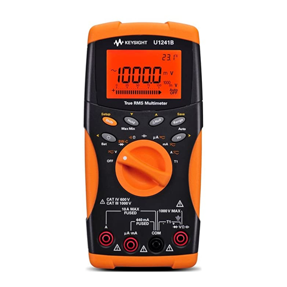
Page 24: The Front Panel At A Glance
Annunciator Keypad Rotary Switch Input Terminal Figure 1-1 Front panel of a U1241B and U1242B handheld digital multimeters Adjusting Tilt Stand Tilt stand at 30° Tilt stand at 60° Bend the tip of the stand Pull the tilt stand outwards to its maximum reach (approximately 60°) -
Page 25: The Annunciator At A Glance
Measurement range Data hold Low battery indicator T1, T2* or T1 – T2* temperature measurements Auto power off indicator *T2 temperature measurement and delta (T1 – T2) are only available for U1242B. Keysight U1241B and U1242B User’s and Service Guide... -
Page 26: Analog Bar Graph
Bar graph counts Range Counts / Segment Function Diode V, A, Ω, The Keypad and Rotary Switch at a Glance Figure 1-4 Keypad and rotary switch of a U1242B handheld digital multimeter Keysight U1241B and U1242B User’s and Service Guide... -
Page 27: Keypad Descriptions And Functions
> 1 second Press Measures frequency for AC signal Press and hold for > 1 second Starts manual data logging Please use manual ranging to measure AC signal with a DC offset. NOTE Keysight U1241B and U1242B User’s and Service Guide... -
Page 28: The Input Terminal At A Glance
440 mA/1000 V 30 kA/ μA & mA μA mA fast-acting fuse 11 A/1000 V 30 kA/ fast-acting fuse Temperature –T1 1000 V R.M.S. 440 mA/1000 V 30 kA/ Temperature (for U1242B only) –T2 fast-acting fuse Keysight U1241B and U1242B User’s and Service Guide... - Page 29 Alerts and Warning During Measurement This chapter contains the detailed information on how to configure connections to perform the multimeter measurements using the U1241B and U1242B handheld digital multimeters. It builds on information already provided in the Quick Start Guide.
-
Page 30: Features And Functions
Measuring DC Voltage Measuring AC Voltage Press to select (U1241B) or AC voltage (U1242B) measurement mode. Measuring Current (> 440 mA) Measuring DC current Measuring AC current Press select AC current measurement mode. Keysight U1241B and U1242B User’s and Service Guide... -
Page 31: Measuring Current (< 440 Ma)
4-20 or 0-20 is indicated on primary display and the bar graph indicates the current value. The 25% scale readout Press represents DC 8 mA at 4 – 20mA, and DC 5 mA at 0 – 20mA. position Keysight U1241B and U1242B User’s and Service Guide... -
Page 32: Measuring Frequency
10.000 kΩ < 100 Ω to enable the 100.00 kΩ < 1 kΩ continuity test function 1.0000 MΩ < 10 kΩ 10.000 MΩ < 100 kΩ 100.00 MΩ < 1 MΩ Keysight U1241B and U1242B User’s and Service Guide... -
Page 33: Testing Diodes
The multimeter can display diode forward bias of up to approximately 1.1 V. NOTE Typical diode forward bias is between the range of 0.3 to 0.8 V range with audible beeper sound. Keysight U1241B and U1242B User’s and Service Guide... -
Page 34: Measuring Capacitance
– Do not contact the temperature sensor to any surface that is energized voltage or current sources, such the voltage source will pose a shock hazard. Keysight U1241B and U1242B User’s and Service Guide... - Page 35 4 Touch the measurement surface with the thermocouple probe. 5 Read the display for the relative temperature. The T2 temperature measurement is only available for U1242B. NOTE Keysight U1241B and U1242B User’s and Service Guide...
-
Page 36: Measuring Harmonic Ratio (U1242B)
This function detects switch condition in position normally close (Low level) or normally open (High level) of a circuit with voltage less than 3 V. The switch counter counts the intermittent for longer than 250 μsec. Keysight U1241B and U1242B User’s and Service Guide... -
Page 37: Table 1-3 Table
Each intermittent will increase the counter once. 6 The counter value and time base are indicated on primary display and secondary display respectively. Press to start next counting. 7 Press to exit switch counter function. Keysight U1241B and U1242B User’s and Service Guide... -
Page 38: Minmax Recording
– If an overload is recorded, the averaging function will stop and the average value becomes OL (overload). – The auto power off feature ( ) is disabled in MinMax Recording mode. Keysight U1241B and U1242B User’s and Service Guide... -
Page 39: Data Hold (Trigger Hold)
– For resistance and diode measurements, the holding value will not be updated if the reading is in “OL” (open state). – The holding value may not be updated if the reading does not reach stable state for all measurements. Keysight U1241B and U1242B User’s and Service Guide... -
Page 40: Null (Relative)
Data logging records only the value on primary display. Two options of data logging are offered — Hand (manual) logging and Interval (automatic) logging functions. Keysight U1241B and U1242B User’s and Service Guide... -
Page 41: Manual Logging
(Log) for more than one second to store the present value and function on primary display to memory. 2 Press (Log) again for the next value that you want to save into memory, Figure 2-1. Keysight U1241B and U1242B User’s and Service Guide... -
Page 42: Interval Logging
Setup mode, see Figure 2-2. 3 Press (Log) for more than one second to exit this mode. When interval (automatic) logging is enabled, all keypad operation is disabled, NOTE except for Log function. Keysight U1241B and U1242B User’s and Service Guide... -
Page 43: Reviewing Logged Data
(View) for more than one second to exit Log View mode. Removing Logged Data Press (Log) for more than one second at the respective Log Review mode (hand or interval) to clear all logged data in the memory. Keysight U1241B and U1242B User’s and Service Guide... -
Page 44: Scanning Temperature Measurement (U1242B)
2 The primary display illustrates the flashing bAt annunciator and the bar graph indicates the battery capacity in proportional percentage from 4.2 V (0%) to 6.0 V (100%). Figure 2-3 Battery capacity display Keysight U1241B and U1242B User’s and Service Guide... -
Page 45: Alerts And Warning During Measurement
The multimeter sounds an alerting beep when the μA/mA input terminal detects a voltage level of more than 1.6 V. The display indicates a flashing CErr annunciator until the test lead is removed from the μA/mA input terminal. Keysight U1241B and U1242B User’s and Service Guide... - Page 46 Features and Functions THIS PAGE HAS BEEN INTENTIONALLY LEFT BLANK. Keysight U1241B and U1242B User’s and Service Guide...
-
Page 47: Default Setting Configurations
Keysight U1241B and U1242B Handheld Digital Multimeter User’s and Service Guide Default Setting Configurations Setting Configurations This chapter describes on how to change and configure the default setting of U1241B and U1242B handheld digital multimeters including data logging and other setting features. -
Page 48: Setting Configurations
3 Press (Save) to save the changes. These parameters remain in the non-volatile memory. 4 Press and hold (Setup) for more than one second to exit Setup mode. Keysight U1241B and U1242B User’s and Service Guide... -
Page 49: Available Setting Options In Setup Mode
Defines the preferred setup of AC or DC for voltage and current voltage and current measurement once (For firmware version measurements multimeter is turned on. 2.13 and below) (For firmware version 2.14 and above) Keysight U1241B and U1242B User’s and Service Guide... -
Page 50: Table 2-1 Table
[d] After this setting has been changed, resetting the multimeter will not revert it to the original default factory setting. The current setting will be the new default setting. Keysight U1241B and U1242B User’s and Service Guide... - Page 51 Keysight U1241B and U1242B Handheld Digital Multimeter User’s and Service Guide Service and Maintenance General Maintenance Battery Replacement Fuse Replacement Troubleshooting Returning Instrument for Service This chapter provides you with warranty services, maintenance procedures and troubleshooting hints to solve general problems that you may encounter with the instrument.
-
Page 52: Service And Maintenance
See the following procedures for battery replacement: 1 At the rear panel, lift up the stand. 2 Loosen the screw on the battery cover. Keysight U1241B and U1242B User’s and Service Guide... - Page 53 4 Replace the specified batteries, ensure the correct polarity of batteries. 5 Reverse the procedures of opening the cover to close the battery cover. Battery Types ANSI/NEDA Alkaline LR03 Zinc Chloride battery cover screw Figure 4-1 Battery replacement Keysight U1241B and U1242B User’s and Service Guide...
-
Page 54: Fuse Replacement
4-3) to lift and remove the circuit board from top case. 6 Gently remove the defective Fuse 2 by prying one end of the fuse loose and removing it out of the fuse bracket, see Figure 4-3. Keysight U1241B and U1242B User’s and Service Guide... -
Page 55: Troubleshooting
If the instrument fails to operate, check the batteries and test leads, replace them if necessary. If the instrument still does not function, check the identification procedures as described in Table 4-1. Keysight U1241B and U1242B User’s and Service Guide... - Page 56 Fast blow fuse 1000 V, 0.44 A (10 mm x 35 mm) 2110-1402 Fast blow fuse 1000 V, 11 A (10 mm x 35 mm) U1241-46400 Battery cover (without screw) 5190-2573 Battery cover screw Keysight U1241B and U1242B User’s and Service Guide...
-
Page 57: Returning Instrument For Service
You are recommended to use the original shipping material or order materials from a Keysight Technologies Sales Office. If both options are not available, place 8 to 10 cm (3 to 4 inches) of shock- absorbing and static-free packaging material around the instrument to avoid movement during shipping. - Page 58 Service and Maintenance THIS PAGE HAS BEEN INTENTIONALLY LEFT BLANK. Keysight U1241B and U1242B User’s and Service Guide...
-
Page 59: Recommended Test Equipment
Calibration Adjustments Calibration Count Calibration Errors This chapter contains procedures of performance verification tests and calibration adjustments. The performance tests is meant to verify the U1241B or U1242B handheld digital multimeter to ensure the multimeter is operating within its published specifications. -
Page 60: Performance Tests And Calibration
A 1-year interval is adequate for most applications. Accuracy specifications are warranted only if adjustment is made at regular calibration intervals. Accuracy specifications are not warranted beyond the 1-year calibration interval. Keysight does not recommend extending calibration intervals beyond 2 years for any application. -
Page 61: Adjustment Is Recommended
Specifications are only guaranteed within the period stated from the last adjustment. Keysight recommends that readjustment should be performed during the calibration process for best performance. This will assure that the U1241B/ U1242B will remain within specification. This criteria for re-adjustment provides the best long–term stability. -
Page 62: Recommended Test Equipment
<1/5 instrument 1 year specifications K-type thermal sensor Temperature K-type thermocouple extension — Shorting Plug - Dual banana plug with copper wire Short <1/5 instrument 1 year specifications short between 2 terminals Keysight U1241B and U1242B User’s and Service Guide... -
Page 63: Basic Operating Test
To view all segments of the display, press and hold the button while turning the rotary switch from OFF to any non-OFF position. Compare the display with the Figure 5-1. Figure 5-1 Annunciator display Keysight U1241B and U1242B User’s and Service Guide... -
Page 64: Input-A Terminal Test
6 Secure the multimeter against unauthorized calibration, see Exiting Adjustment Mode. Ensure that the multimeter has quit the Adjustment Mode and turned off. 7 Record the new security code and calibration count in the multimeter’s maintenance records. Keysight U1241B and U1242B User’s and Service Guide... -
Page 65: Test Considerations
During DC voltage, DC current, and resistance gain verification measurements, ensure that the calibrator's “0” output is correct. It is recommended to set the offset for each range of the measuring function being verified. Keysight U1241B and U1242B User’s and Service Guide... -
Page 66: Input Connections
If the multimeter fails performance verification, adjustment or repair is required. Users are highly recommended to read the Test Considerations before NOTE performing performance verification tests. Keysight U1241B and U1242B User’s and Service Guide... -
Page 67: Verification Tests
1.000 V, 1000 Hz ± 600 mHz Press to go to frequency mode 10 kHz 1.000 V, 2 kHz ± 3.6 Hz position Diode 1.000 V ± 5 mV Turn the rotary switch to Keysight U1241B and U1242B User’s and Service Guide... - Page 68 100 mA 100.00 mA, 1 kHz ± 1.55 mA Press to go to ± 4.5 mA 400 mA , 500 Hz function 440 mA ± 6.5 mA 400 mA , 1 kHz Keysight U1241B and U1242B User’s and Service Guide...
-
Page 69: Table 3-1 Table
(without internal ambient compensation 0 ºC). If both calibrator and multimeter are set with internal reference (with internal ambient compensation), deviation may be present between the readings of the calibrator and multimeter. Keysight U1241B and U1242B User’s and Service Guide... -
Page 70: Calibration Security
5 If the correct security code is entered, the secondary display will show “PAS”. If an invalid code is entered, the multimeter will shows error code “E02” on the secondary display for approximately 3 seconds and return to the Calibration Security entry mode. Keysight U1241B and U1242B User’s and Service Guide... - Page 71 Press to change the value of the selected character. 6 Set the code, same as the last 4 digit serial number of the multimeter. Press (Save) to confirm the entry. Keysight U1241B and U1242B User’s and Service Guide...
-
Page 72: Using The Front Panel For Adjustments
3 Apply the respective corresponding input signal from the recommended test equipment in Table 5-1. 4 Press (Save) when done to start calibration. Ensure that the accuracy of the input signal adheres to the Valid Adjustment NOTE Input Values Table 5-3. Keysight U1241B and U1242B User’s and Service Guide... -
Page 73: Adjustment Considerations
K-type thermocouple connected between the multimeter and calibration source. Do not turn off the multimeter during adjustments., as this may delete the CAUTION calibration memory for the present function. Keysight U1241B and U1242B User’s and Service Guide... -
Page 74: Valid Adjustment Input Values
0.9 to 1.1 x Full Scale (T1) The minimum AC current output of Fluke 5520A calibrator is 29 μA. Ensure CAUTION that at least 50 μA is set at the calibrator source of AC μA. Keysight U1241B and U1242B User’s and Service Guide... -
Page 75: Calibration Adjustments
The primary display remains at the current Cal Item. If the adjustment failed, check the input value, range, function, and entered NOTE adjustment value and repeat the adjustment steps. Keysight U1241B and U1242B User’s and Service Guide... - Page 76 100 V 100 V, 70 Hz 100.00 V 100 V, 1 kHz 100.00 V 100 V, 70 Hz 100.0 V 1000 V 1000 V, 70 Hz 1000.0 V 1000V, 1 kHz 1000.0 V Keysight U1241B and U1242B User’s and Service Guide...
- Page 77 1000.0 nF Turn the rotary switch to position 10 μF 10 μF 10.000 μF 100 μF 100 μF 100.00 μF 1000 μF 1000 μF 1000.0 μF 10 mF 10 mF 10.000 mF Keysight U1241B and U1242B User’s and Service Guide...
- Page 78 100 mA 10 mA, 70 Hz 10.00 mA Press to go to 100 mA, 70 Hz 100.00 mA function 100 mA, 70 Hz 100.0 mA 1000 mA 320 mA, 70 Hz 320.0 mA Keysight U1241B and U1242B User’s and Service Guide...
-
Page 79: Exiting Adjustment Mode
1 Remove all shorting plugs and connectors from the multimeter. 2 Record the new Calibration Count, see Calibration Count. 3 Press simultaneously to exit the Adjustment Mode. Power off and on the multimeter to return to normal measurement mode and secured. Keysight U1241B and U1242B User’s and Service Guide... -
Page 80: Calibration Count
Calibration error: Invalid serial number code Calibration error: Calibration aborted Calibration error: Value out of range Calibration error: Signal measurement out of range Calibration error: Frequency out of range EEPROM write failure Keysight U1241B and U1242B User’s and Service Guide... -
Page 81: Characteristics And Specifications
Keysight U1241B and U1242B Handheld Digital Multimeter User’s and Service Guide Characteristics and Specifications For the characteristics and specifications of the U1241B and U1242B Handheld Digital Multimeter, refer to the datasheet at http://literature.cdn.keysight.com/litweb/pdf/5989-7040EN.pdf. - Page 82 Characteristics and Specifications THIS PAGE HAS BEEN INTENTIONALLY LEFT BLANK. Keysight U1241B and U1242B User’s and Service Guide...
- Page 83 This information is subject to change without notice. Always refer to the Keysight website for the latest revision. © Keysight Technologies 2009 - 2016 Edition 17, March 18, 2016 Printed in Malaysia *U1241-90063* U1241-90063 www.keysight.com...
Need help?
Do you have a question about the U1241B and is the answer not in the manual?
Questions and answers