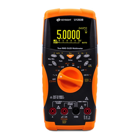
Keysight U1253B Quick Start Manual
True rms oled
Hide thumbs
Also See for U1253B:
- Quick start manual (16 pages) ,
- Quick start manual (21 pages) ,
- Quick start manual (193 pages)
Summary of Contents for Keysight U1253B
- Page 1 All manuals and user guides at all-guides.com Keysight U1253B True RMS OLED Multimeter Quick Start Guide...
- Page 2 Do not proceed beyond a WARNING notice until the indicated conditions are fully understood and met. For further safety information details, refer to the Keysight U1253B True RMS OLED Multimeter User’s and Service Guide. Keysight U1253B Quick Start Guide...
-
Page 3: Table Of Contents
Measurements ..... . . 18 Square Wave Output ....20 Keysight U1253B Quick Start Guide... - Page 4 All manuals and user guides at all-guides.com THIS PAGE HAS BEEN INTENTIONALLY LEFT BLANK. Keysight U1253B Quick Start Guide...
- Page 5 If anything is missing or damaged, please contact the nearest Keysight Sales Office. For more detailed information, please refer to the Keysight U1253B True RMS OLED Multimeter User’s and Service Guide on Keysight website (www.keysight.com/find/handheld-tools). Ensure the terminal connections are correct for that...
-
Page 6: Charging The Battery
4 The display will show a countdown timer of 10 seconds for the self-test to start. The multimeter will output short single-tone sounds to remind you to charge the battery. Press to start charging the battery, or the multimeter will automatically start Keysight U1253B Quick Start Guide... - Page 7 – A new rechargeable battery comes in a discharged condition and must be charged before use (refer to the U1253B User's and Service Guide for charging instructions). – Upon initial use (or after a prolonged storage...
-
Page 8: Functions And Features
> 1 s. Your multimeter is capable of remote data logging. NOTE To use this feature, you will need an IR-USB cable (U1173A, purchased separately) and the Keysight GUI Data Logger Software (downloadable from www.keysight.com/find/hhTechLib). Keysight U1253B Quick Start Guide... -
Page 9: Input Terminals And Overload Protection
Overload Protection Voltage 1000 Vrms Diode 1000 Vrms < 0.3 A short circuit Resistance current Capacitance Temperature Current (μA and mA) µA.mA 440 mA/1000 V 30 kA/fast-acting fuse Current (A) 11 A/1000 V 30 kA/fast-acting fuse Keysight U1253B Quick Start Guide... -
Page 10: Performing Voltage Measurements
2 Connect the red and black test leads to input terminals V. mV (red) and COM (black) respectively. 3 Probe the test points and read the display. 4 Press to display dual measurements. Parameter can be switched consecutively. Keysight U1253B Quick Start Guide... - Page 11 2 Connect the red and black test leads to input terminals V. mV (red) and COM (black) respectively. 3 Probe the test points and read the display. 4 Press to display dual measurements. Parameter can be switched consecutively. Keysight U1253B Quick Start Guide...
- Page 12 To avoid possible electric shock or personal injury, CAUTION enable the Filter to verify the presence of hazardous DC voltages. Displayed DC voltages can be influenced by high frequency AC components and must be filtered to assure an accurate reading. Keysight U1253B Quick Start Guide...
-
Page 13: Performing Current Measurements
2 Connect the red and black test leads to input terminals µA.mA (red) and COM (black) or A (red) and COM (black) respectively. 3 Probe the test points in series with the circuit and read the display. Keysight U1253B Quick Start Guide... - Page 14 CAUTION black test leads to input terminals µA.mA (red) and COM (black). – If the current is > 440 mA, connect the red and black test leads to input terminals A (red) and COM (black). Keysight U1253B Quick Start Guide...
-
Page 15: Performing Resistance, Conductance, And Continuity Measurements
3 Probe the test points (by shunting the resistor) and read the display. 4 Press to scroll through audible continuity ( ), conductance ( ), and resistance tests ( , or ) as shown. Keysight U1253B Quick Start Guide... -
Page 16: Performing Capacitance And Temperature Measurements
2 Connect the red and black test leads to input terminals (red) and COM (black) respectively. 3 Connect the red test lead to the positive terminal of the capacitor, and the black test lead to the negative terminal. 4 Read the display. Keysight U1253B Quick Start Guide... - Page 17 (red) and COM (black) respectively. 3 Plug the thermocouple adapter (with the thermocouple probe connected to it) into input terminals (red) and COM (black). 4 Touch the measurement surface with the thermocouple probe. 5 Read the display. Keysight U1253B Quick Start Guide...
-
Page 18: Frequency And Frequency Counter Measurements
1 Set the rotary switch to 2 Press to select the frequency counter ) function. The default input signal frequency is divided by 1. This allows signals up to a maximum frequency of 985 kHz to be measured. Keysight U1253B Quick Start Guide... - Page 19 100 ( will be shown on the display). This accommodates a higher frequency range of up to 20 MHz. 6 The signal is out of the U1253B frequency measurement range of 20 MHz if the reading is still unstable after step –...
-
Page 20: Square Wave Output
(there are 28 frequencies to choose from). 5 Press to adjust the duty cycle. The duty cycle can be set from 0.390625% to 99.609375%, in steps of 0.390625%. The displayed duty cycle has a resolution of 0.001%. Keysight U1253B Quick Start Guide... - Page 21 All manuals and user guides at all-guides.com This information is subject to change without notice. Always refer to the Keysight website for the latest revision. © Keysight Technologies 2009-2017 Edition 6, June 1, 2017 Printed in Malaysia *U1253-90045* U1253-90045 www.keysight.com...


Need help?
Do you have a question about the U1253B and is the answer not in the manual?
Questions and answers