Sign In
Upload
Download
Table of Contents
Contents
Add to my manuals
Delete from my manuals
Share
URL of this page:
HTML Link:
Bookmark this page
Add
Manual will be automatically added to "My Manuals"
Print this page
×
Bookmark added
×
Added to my manuals
Manuals
Brands
Keysight Manuals
Multimeter
U1251
Quick start manual
Keysight U1251 Quick Start Manual
Handheld digital multimeter
Hide thumbs
1
2
3
4
5
6
7
8
9
10
11
12
13
14
15
Table Of Contents
16
page
of
16
Go
/
16
Contents
Table of Contents
Bookmarks
Table of Contents
Charging the Battery
Functions and Features
Input Terminals and Overload Protection
Performing Voltage Measurements
Measuring Ac Voltage
Performing Current Measurements
Performing Resistance, Conductance, and Continuity Measurements
Frequency and Frequency Counter Measurements
Square Wave Output (for U1252B Only)
Safety Notices
Safety Information
Safety Symbols
Advertisement
Quick Links
Download this manual
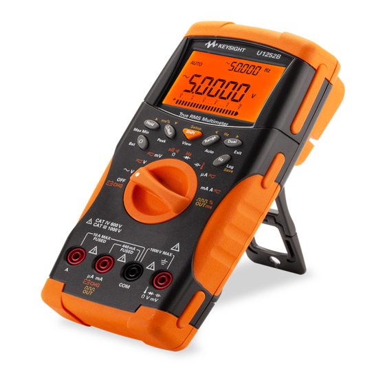
Keysight U1251B and U1252B
Handheld Digital Multimeter
Quick Start Guide
Table of
Contents
Previous
Page
Next
Page
1
2
3
4
5
Advertisement
Table of Contents
Need help?
Do you have a question about the U1251 and is the answer not in the manual?
Ask a question
Questions and answers
Related Manuals for Keysight U1251
Multimeter Keysight U1251B User's And Service Manual
Handheld digital multimeter (198 pages)
Multimeter Keysight U1251B User And Service Manual
Handheld (173 pages)
Multimeter Keysight U1251B Quick Start Manual
(21 pages)
Multimeter Keysight U1251B Quick Start Manuals
Handheld digital multimeter (178 pages)
Multimeter Keysight U1252B User's And Service Manual
Handheld digital multimeter (722 pages)
Multimeter Keysight U1253B Quick Start Manual
True rms oled multimeter (16 pages)
Multimeter Keysight U1253B Quick Start Manual
True rms oled (21 pages)
Multimeter Keysight U1253B Quick Start Manual
True rms oled multimeter (193 pages)
Multimeter Keysight U1253B Quick Start Manual
True rms oled (21 pages)
Multimeter Keysight U1252 Quick Start Manual
Handheld digital multimeter (16 pages)
Multimeter Keysight U1271A Quick Start Manual
(166 pages)
Multimeter Keysight u1272a Quick Start Manual
Handheld (22 pages)
Multimeter Keysight U1271A Service Manual
Handheld? u1270 series (63 pages)
Multimeter Keysight keysight u1273a Quick Start Manual
Handheld (24 pages)
Multimeter Keysight U1273A Quick Start Manual
Handheld digital multimeter (25 pages)
Multimeter Keysight U1241C Quick Start Manual
Handheld digital multimeter (30 pages)
This manual is also suitable for:
U1252
Table of Contents
Print
Rename the bookmark
Delete bookmark?
Delete from my manuals?
Login
Sign In
OR
Sign in with Facebook
Sign in with Google
Upload manual
Upload from disk
Upload from URL


Need help?
Do you have a question about the U1251 and is the answer not in the manual?
Questions and answers