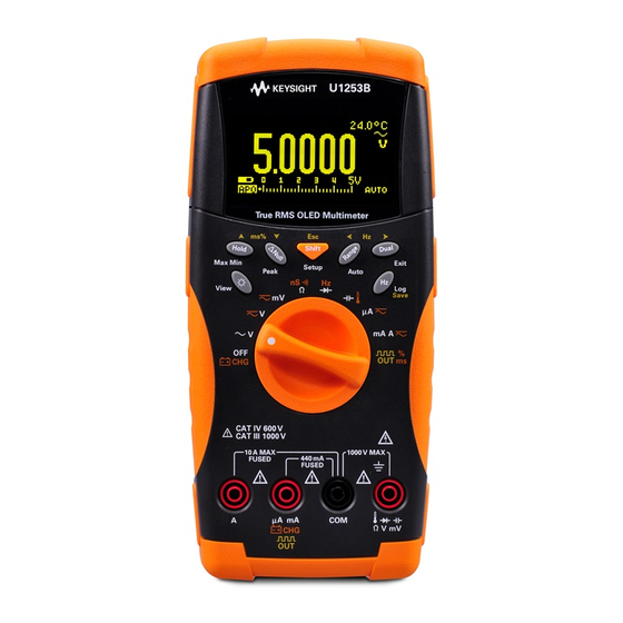
Keysight U1253B Quick Start Manual
True rms oled multimeter
Hide thumbs
Also See for U1253B:
- Quick start manual (21 pages) ,
- Quick start manual (193 pages) ,
- Quick start manual (21 pages)
Table of Contents
Advertisement
Quick Links
Download this manual
See also:
Quick Start Manual
Advertisement
Table of Contents

Related Manuals for Keysight U1253B


Summary of Contents for Keysight U1253B
- Page 1 Keysight U1253B True RMS OLED Multimeter Quick Start Guide...
-
Page 3: Keysight U1253B True Rms Oled Multimeter
Printed Quick Start Guide If anything is missing or damaged, please contact the nearest Keysight Sales Office. For more detailed information, please refer to the Keysight U1253B True RMS OLED Multimeter User’s and Service Guide on Keysight Web site (www.keysight.com/find/handheld-tools). -
Page 4: Charging The Battery
• Ensure proper insertion of battery in the multimeter, and follow the correct polarity. • A new rechargeable battery comes in a discharged condition and must be charged before use (refer to the U1253B User's and Service Guide for charging instructions). U1253A Quick Start Guide... -
Page 5: Functions And Features
> 1 s. Your multimeter is capable of remote data logging. To use this NO TE feature, you will need an IR-USB cable (U1173A, purchased separately) and the Keysight GUI Data Logger Software (downloadable from www.keysight.com/find/hhTechLib). U1253A Quick Start Guide... -
Page 6: Input Terminals And Overload Protection
Input Terminals and Overload Protection Measurement Functions Input Terminal Overload Protection Voltage 1000 Vrms Diode 1000 Vrms < 0.3 A short circuit cur- Resistance rent Capacitance Temperature Current (μA and mA) µA.mA 440 mA/1000 V 30 kA/fast-acting fuse Current (A) 11 A/1000 V 30 kA/fast-acting fuse U1253A Quick Start Guide... -
Page 7: Performing Voltage Measurements
Performing Voltage Measurements Measuring AC voltage 1 Set the rotary switch to . For mode, press to ensure is shown on the display. 2 Connect the red and black test leads to input terminals V. mV (red) and COM (black) respectively. 3 Probe the test points and read the display. -
Page 8: Using The Filter
Using the Filter 1 Press and hold for more than 1 sec- ond to enter the multimeter’s Setup menu. 2 Press to scroll to menu 6. 3 Press to browse to the DC Filter option. 4 Press to enter the Edit mode. 5 Press to enable the DC Filter. -
Page 9: Performing Current Measurements
Performing Current Measurements To perform current measurements, set up your multimeter as shown in the figure below. For measuring DC current from a mixed signal in DC measure- ment mode, ensure that the Filter is enabled. Measuring AC current 1 Set the rotary switch to . -
Page 10: Performing Resistance, Conductance, And Continuity Measurements
Performing Resistance, Conductance, and Continuity Measurements PRESS SHIFT Audible continuity PRESS SHIFT 1 Set the rotary switch to 2 Connect the red and black test leads to input terminals Ω (red) and COM (black) respectively. 3 Probe the test points (by shunting the resistor) and read the display. 4 Press to scroll through audible continuity ( ), conduc-... - Page 11 Performing Capacitance and Temperature Measurements Capacitance 1 Set the rotary switch to 2 Connect the red and black test leads to input terminals (red) and COM (black) respectively. 3 Connect the red test lead to the positive terminal of the capacitor, and the black test lead to the negative terminal.
-
Page 12: Frequency Counter Measurement
This accommodates a higher frequency range of up to 20 MHz. 6 The signal is out of the U1253B frequency measurement range of 20 MHz if the read- ing is still unstable after step •... -
Page 13: Square Wave Output
Square Wave Output 1 Turn the rotary switch to 2 Press to select duty cycle (%) on the primary display. 3 The default square wave frequency is 600 Hz as shown by the secondary display, with a 50% duty cycle as shown by the pri- mary display. -
Page 14: Safety Notices
Second Edition and CAN/CSA 22.2 61010-1 Second Edition, CAT III 1000 V/Category IV 600 V, Pollution Degree II. Use with standard or compatible test probes. For further safety information details, refer to the Keysight U1253B True RMS OLED Multimeter User’s and Service Guide. - Page 15 This information is subject to change without notice. © Keysight Technologies 2009 - 2014 Edition 5, August 2014 *U1253-90045* U1253-90045 www.keysight.com...
Need help?
Do you have a question about the U1253B and is the answer not in the manual?
Questions and answers