Sign In
Upload
Manuals
Brands
Keysight Manuals
Multimeter
U1251B
Keysight U1251B Manuals
Manuals and User Guides for Keysight U1251B. We have
5
Keysight U1251B manuals available for free PDF download: User's And Service Manual, Quick Start Manuals, User And Service Manual, Quick Start Manual
Keysight U1251B User's And Service Manual (722 pages)
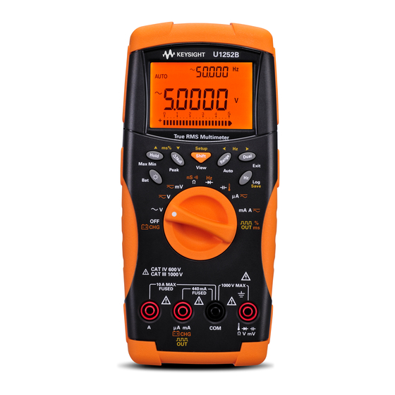
Handheld Digital Multimeter
Brand:
Keysight
| Category:
Multimeter
| Size: 29 MB
Table of Contents
English
15
Safety Symbols
3
General Safety Information
4
Measurement Category
7
Environmental Conditions
8
Regulatory Markings
9
Waste Electrical and Electronic Equipment (WEEE) Directive 2002/96/EC
10
Product Category
10
Sales and Technical Support
10
In this Guide
12
Table of Contents
15
Getting Started
23
Introducing the U1251B/U1252B Handheld Digital Multimeter
24
Check the Shipment
25
Installing the Battery
26
Adjusting the Tilt-Stand
28
Figure 1-1 Tilt-Stand at
28
Figure 1-2 Tilt-Stand at
28
Figure 1-3 Tilt-Stand at Hanging Position
29
The Front Panel at a Glance
30
Figure 1-4 U1252B Front Panel
30
The Rear Panel at a Glance
31
Figure 1-5 Rear Panel
31
The Rotary Switch at a Glance
32
Figure 1-6 Rotary Switch
32
Table 1-1 Rotary Switch Description and Functions
32
The Keypad at a Glance
33
Figure 1-7 U1252B Keypad
33
Table 1-2 Keypad Descriptions and Functions
33
The Display at a Glance
35
Figure 1-8 Display Symbols
35
Table 1-3 General Display Symbols
36
Table 1-4 Primary Display Symbols
38
Table 1-5 Secondary Display Symbols
38
Table 1-6 Analog Bar Range and Counts
40
Selecting Display with the Hz Button
41
Table 1-7 Selecting Display with the Hz Button
42
Selecting Display with the Dual Button
44
Table 1-8 Selecting Display with the Dual Button
44
Selecting Display with the Shift Button
47
Table 1-9 Selecting Display with the Shift Button
47
The Terminals at a Glance
48
Figure 1-9 Connector Terminals
49
Making Measurements
51
Understanding the Measurement Instructions
52
Measuring Voltage
52
Table 2-1 Numerical Steps Descriptions
52
Measuring AC Voltage
53
Figure 2-1 Measuring AC Voltage
53
Measuring DC Voltage
54
Figure 2-2 Measuring DC Voltage
54
Measuring AC and DC Signals (U1252B Only)
55
Μa & Ma Measurement
56
Measuring Current
56
Figure 2-3 Measuring Ma and Ma Current
57
Percentage Scale of 4 Ma to 20 Ma
58
Table 2-2 Percentage Scale and Measurement Range
58
Figure 2-4 Measuring Scale of 4-20 Ma
59
A (Ampere) Measurement
60
Figure 2-5 a (Ampere) Current Measurement
60
Frequency Counter
61
Figure 2-6 Measuring Frequency
62
Measuring Resistance, Conductance and Testing Continuity
63
Figure 2-7 Measuring Resistance
63
Table 2-3 Audible Continuity Measurement Range
65
Figure 2-9 Conductance Measurement
66
Testing Diodes
67
Figure 2-10 Measuring Forward Bias of Diode
68
Figure 2-11 Measuring Reverse Bias of Diode
69
Measuring Capacitance
70
Figure 2-12 Capacitance Measurements
71
Measuring Temperature
72
Figure 2-13 Connecting the Thermal Probe into the Non-Compensation Transfer Adapter
73
Figure 2-14 Connecting the Probe with Adapter into the Multimeter
73
Figure 2-15 Surface Temperature Measurement
75
Alerts and Warning During Measurement
76
Overload Alert
76
Input Warning
76
Figure 2-16 Input Terminal Warning
76
Charge Terminal Alert
77
Figure 2-17 Charge Terminal Alert
77
Functions and Features
79
Dynamic Recording
80
Figure 3-1 Dynamic Recording Mode Operation
81
Data Hold (Trigger Hold)
82
Figure 3-2 Data Hold Mode Operation
82
Refresh Hold
83
Figure 3-3 Refresh Hold Mode Operation
84
Null (Relative)
85
Figure 3-4 Null (Relative) Mode Operation
86
Decibel Display
87
Figure 3-5 Dbm/Dbv Display Mode Operation
88
Ms Peak Hold
89
Figure 3-6 1Ms Peak Hold Mode Operation
90
Data Logging
91
Manual Logging
91
Interval Logging
93
Figure 3-9 Interval (Automatic) Logging Mode Operation
94
Reviewing Logged Data
95
Figure 3-10 Log Review Mode Operation
96
Square Wave Output (for U1252B)
97
Figure 3-11 Frequency Adjustment for Square Wave Output
98
Figure 3-12 Pulse Width Adjustment for Square Wave Output
99
Figure 3-13 Pulse Width Adjustment for Square Wave Output
100
Figure 3-14 Cable Connection for Remote Communication
101
Remote Communication
101
Changing the Default Setting
103
Selecting Setup Mode
104
Table 4-1 Available Setting Options in Setup Mode
105
Setting Data Hold/Refresh Hold Mode
108
Figure 4-1 Data Hold/Refresh Hold Setup
108
Setting Data Logging Mode
109
Figure 4-2 Data Logging Setup
109
Setting Thermocouple Types (U1252B Only)
110
Figure 4-3 Thermocouple Type Setup
110
Setting Reference Impedance for Dbm Measurement
111
Figure 4-4 Reference Impedance for Dbm Measurement Setup
111
Setting Minimum Frequency Measurement
112
Figure 4-5 Minimum Frequency Setup
112
Setting Temperature Unit
113
Figure 4-6 Temperature Unit Setup
114
Setting Auto Power Saving Mode
115
Figure 4-7 Auto Power Saving Setup
116
Setting Percentage (%) Scale Readout
117
Figure 4-8 % Scale Readout Setup
117
Setting Beep Frequency
118
Figure 4-9 Beep Frequency Setup
118
Setting Backlight Timer
119
Figure 4-10 Backlit Timer Setup
119
Setting Baud Rate
120
Figure 4-11 Baud Rate Setup Remote Control
120
Setting Parity Check
121
Figure 4-12 Parity Check Setup
121
Setting Data Bit
122
Figure 4-13 Data Bit Setup for Remote Control
122
Setting Echo Mode
123
Figure 4-14 Echo Mode Setup for Remote Control
123
Setting Print Mode
124
Figure 4-15 Print Mode Setup for Remote Control
124
Returning to Default Factory Settings
125
Figure 4-16 Reset Setup
125
Setting the Battery Voltage
126
Figure 4-17 Battery Voltage Selection
126
Setting the Filter
127
Figure 4-18 DC Filter
127
Table 4-2 Filter Defaults
128
Maintenance
129
Battery Replacement
130
General Maintenance
130
Introduction
130
Storage Considerations
132
Figure 5-1 9 V Rectangular Battery
132
Charging the Battery
133
Table 5-1 Battery Voltage and Corresponding Percentage of Charges in Standby and Charging Modes
134
Figure 5-2 Battery Capacity Display as Trickle
135
Figure 5-3 Self-Test
136
Table 5-2 Error Messages
136
Figure 5-4 Charging Mode
138
Figure 5-5 Charge End and Trickle State
138
Figure 5-6 Battery Charging Procedure
140
Fuse Checking Procedure
141
Figure 5-7 Fuse Checking Procedures
141
Table 5-3 Measurement Readings for Fuse Checking
142
Replacing the Fuse
143
Figure 5-8 Fuse Replacement
144
Table 5-4 Fuse Specifications
144
Troubleshooting
145
Table 5-5 Basic Troubleshooting Procedures
145
Replaceable Parts
146
To Order Replaceable Parts
146
Performance Tests and Calibration
148
Calibration Overview
148
Closed-Case Electronic Calibration
148
Keysight Technologies Calibration Services
148
Calibration Interval
149
Adjustment Is Recommended
149
Recommended Test Equipment
150
Table 6-1 Recommended Test Equipment
150
Basic Operating Test
151
Backlit Test
151
Testing the Display
151
Figure 6-1 LCD Display
151
Current Terminal Test
152
Figure 6-2 Input Warning
152
Charge Terminal Alert Test
153
Figure 6-3 Charge Terminal Alert
153
Test Considerations
154
Calibration Security
155
Performance Verification Tests
156
Table 6-2 Verification Test
157
Unsecuring the Instrument for Calibration
163
Calibration Process
166
Using the Front Panel for Adjustments
167
Adjustments Consideration
168
Valid Adjustment Input Values
169
Table 6-3 Valid Adjustment Input Values
169
Adjustment Procedure
170
Table 6-4 Adjustment Table
172
Finishing the Adjustment
177
To Read the Calibration Count
177
Calibration Errors
178
Table 6-5 Calibration Error Codes and Their Respective Meanings
178
Specifications
179
Français
194
Mise en Route
204
Présentation des Multimètres Numériques Portables U1251B/U1252B
205
Vérification de la Livraison
206
Installer les Piles
207
Réglage de la Béquille D'inclinaison
209
Le Panneau Avant D'un Coup D'œil
211
Le Panneau Arrière D'un Coup D'oeil
212
Le Commutateur Rotatif D'un Coup D'œil
213
Tableau 1-1 Description et Fonctions du Commutateur Rotatif
213
Le Clavier D'un Coup D'œil
214
Tableau 1-2 Keypad Descriptions and Functions
214
L'écran D'un Coup D'œil
217
Tableau 1-3 Symboles de L'affichage Général
218
Tableau 1-4 Symboles de L'affichage Principal
219
Tableau 1-5 Symboles de L'affichage Secondaire
220
Tableau 1-6 Plage et Points de la Barre Analogique
221
Sélection de L'affichage à L'aide de la Touche Hz
222
Tableau 1-7 Sélection de L'affichage à L'aide de la Touche Hz
222
Sélection de L'affichage à L'aide de la Touche Dual
224
Tableau 1-8 Sélection de L'affichage à L'aide de la Touche Dual
224
Sélection de L'affichage à L'aide de la Touche Shift
227
Tableau 1-9 Sélection de L'affichage à L'aide de la Touche Shift
227
Les Bornes D'un Coup D'œil
228
Tableau 1-10 Connexions aux Bornes pour les Différentes Fonctions de Mesure
229
Réalisation des Mesures
230
Comprendre les Instructions de Mesure
231
Mesure de Tension
231
Tableau 2-1 Numerical Steps Descriptions
231
Measuring AC Voltage
232
Mesure de Tension Continue
233
Measuring AC and DC Signals (U1252B Only)
234
Mesure de Courant
235
Tableau 2-2 Échelle de Pourcentage et Plage de Mesure
237
Échelle de Pourcentage de 4 Ma à 20 Ma
237
Mesure en a (Ampère)
239
Fréquencemètre
240
Mesures de Résistance et de Conductance, Test de Continuité
242
Tableau 2-3 Plage de Mesure de Continuité Avec Signal Sonore
244
Test de Diodes
246
Mesures de Capacité (Condensateurs)
249
Mesures de Température
251
Alarme de Surcharge
255
Alarmes et Avertissements Lors D'une Mesure
255
Alarme de la Borne de Charge
256
Fonctionnalités
258
Enregistrement Dynamique
259
Gel des Données (Gel du Déclenchement)
261
Rafraîchissement des Valeurs Gelées
262
Mesure Par Rapport à une Valeur de Référence (Relative)
264
Affichage de Décibels
266
Gel de Valeur Crête 1 Ms
268
Enregistrement de Données
270
Enregistrement Manuel
270
Enregistrement à Intervalles
272
Révision des Données Enregistrées
274
Sortie de Signal Carré (pour le U1252B)
276
Communication à Distance
280
Modification de la Configuration Par Défaut
282
Sélection du Mode Setup (Configuration)
283
Tableau 4-1 Options de Configuration Disponibles en Mode Setup
284
Configuration du Mode de Gel des Données/Rafraîchissement
287
Configuration du Mode D'enregistrement de Données
288
Configuration des Types de Thermocouple (Modèle U1252B Uniquement)
289
Configuration de L'impédance de Référence pour les Mesures de Dbm
290
Configuration de la Fréquence Minimale de Mesure
291
Configuration des Échelles de Température
292
Configuration du Mode D'extinction Automatique
294
Configuration de la Valeur D'échelle de Pourcentage (%)
296
Configuration de la Fréquence du Signal Sonore
297
Configuration du Minuteur de Rétroéclairage
298
Configuration du Débit de Données
299
Configuration du Contrôle de Parité
300
Configuration du Nombre de Bits de Données
301
Configuration du Mode D'écho
302
Configuration du Mode D'impression
303
Retour aux Configurations D'usine Par Défaut
304
Réglage de la Tension de la Pile
305
Réglage du Filtre
306
Tableau 4-2 Valeurs Par Défaut du Filtre
307
Maintenance
308
Introduction
309
Maintenance Générale
309
Remplacement de la Pile
309
Considérations de Stockage
311
Charge de la Batterie
312
Tableau 5-1 Tension de la Pile et Pourcentage de Charge Correspondant en Modes Veille et Charge
313
Tableau 5-2 Messages D'erreur
315
Procédure de Vérification des Fusibles
319
Tableau 5-3 Lectures de Mesure pour la Vérification des Fusibles
320
Remplacement du Fusible
321
Tableau 5-4 Caractéristiques des Fusibles
322
Dépannage
323
Tableau 5-5 Procédures de Recherche de Panne de Base
323
Pièces de Rechange
324
Pour Commander des Pièces de Rechange
324
Etalonnage : Généralités
327
Etalonnage Électronique en Boîtier Fermé
327
Périodicité D'étalonnage
327
Services D'étalonnage Keysight Technologies
327
Etalonnage Recommandé
328
Equipement de Test Recommandé
329
Tableau 6-1 Equipement de Test Recommandé
329
Test de L'écran
330
Test du Rétro-Éclairage
330
Tests de Fonctionnement de Base
330
Test de la Borne de Courant
331
Test D'alarme de la Borne de Charge
332
Considérations Sur les Tests
333
Tests de Vérification des Performances
334
Tableau 6-2 Test de Vérification
336
Déverrouillage de la Sécurité de L'instrument à des Fins D'étalonnage
342
Procédure D'étalonnage
345
Etalonnage depuis le Panneau Avant
346
Considérations Relatives à L'étalonnage
347
Tableau 6-3 Valeurs D'entrée Valides pour L'étalonnage
348
Valeurs D'entrée Valides pour L'étalonnage
348
Procédure D'étalonnage
349
Tableau 6-4 Tableau D'étalonnage
351
Pour Lire le Nombre de Points D'étalonnage
356
Pour Terminer L'étalonnage
356
Erreurs D'étalonnage
357
Tableau 6-5 Codes et Significations des Erreurs D'étalonnage
357
Spécifications
358
Italiano
373
Operazioni Preliminari
383
Introduzione al Multimetro Digitale Palmare U1251B/U1252B
384
Verificare la Spedizione
385
Installazione Della Batteria
386
Regolazione del Supporto Inclinabile
388
Panoramica del Panello Anteriore
390
Panoramica del Pannello Posteriore
391
Panoramica del Selettore
392
Panoramica del Tastierino
393
Panoramica del Display
395
Selezione del Display Mediante Il Pulsante Hz
400
Selezione del Display Mediante Il Pulsante Dual
402
Selezione del Display Mediante Il Pulsante Shift
405
Panoramica Sui Puntali
406
Misurazioni
409
Istruzioni Per la Misurazione
410
Misurazione Della Tensione
410
Misurazione Della Tensione CA
411
Misurazione Della Tensione CC
412
Misurazione Dei Segnali CA E CC (solo Per Il Modello U1252B)
414
Misurazione Della Corrente
415
Scala Percentuale da 4 Ma a 20 Ma
417
Misurazione DI Ampere
419
Contatore DI Frequenze
420
Misurazione Della Resistenza E Della Conduttanza E Test DI Continuità
422
Test Dei Diodi
426
Misurazione Della Capacitanza
429
Misurazione Della Temperatura
431
Avvertenza Per Terminale DI Ingresso
435
Avviso DI Sovraccarico
435
Messaggi DI Avvertenza Durante la Misurazione
435
Avviso Per Terminale DI Carica
436
Funzioni E Caratteristiche
437
Registrazione Dinamica
437
Data Hold (Trigger Hold)
440
Refresh Hold
441
Null (Relative)
443
Visualizzazione in Decibel
445
Peak Hold 1 Ms
447
Registrazione Dei Dati
449
Registrazione Manuale
449
Registrazione a Intervalli
451
Verifica Dei Dati Registrati
453
Onda Quadra in Uscita (Per U1252B)
455
Comunicazione Remota
459
Modifica Delle Impostazioni Predefinite
461
Selezione Della Modalità Setup
462
Impostazione Della Modalità Data Hold/Refresh Hold
466
Impostazione Della Modalità DI Registrazione Dei Dati
467
Impostazione Dei Tipi DI Termocoppie (solo Per Il Modello U1252B)
468
Impostazione Dell'impedenza DI Riferimento Per la Misurazione in Dbm
469
Impostazione Della Misurazione Della Frequenza Minima
470
Impostazione Dell'unità DI Temperatura
471
Impostazione Della Modalità Automatica DI Risparmio Energetico
473
Impostazione Della Lettura in Scala Percentuale (%)
475
Impostazione Della Frequenza del Segnale Acustico
476
Impostazione del Timer Della Retroilluminazione
477
Figura
478
Il Controllo Remoto
478
Impostazione Della Velocità DI Trasmissione
478
Impostazione del Controllo DI Parità
479
Impostazione Della Lunghezza Dei Bit Dei Dati
480
Impostazione Della Modalità Echo
481
Impostazione Della Modalità DI Stampa
482
Figura
483
Impostazione Dell'operazione DI Reset
483
Ripristino Delle Impostazioni DI Fabbrica
483
Figura
484
Impostazione Della Tensione Della Batteria
484
Selezione Della Tensione Della Batteria
484
Figura
485
Filtro CC
485
Impostazione del Filtro
485
Manutenzione
487
Introduzione
488
Manutenzione Generale
488
Sostituzione Delle Batterie
488
Batteria Rettangolare da 9 Volt
490
Considerazioni Per lo Stoccaggio
490
Figura
490
Carica Della Batteria
491
Capacità Della Batteria in Carica DI Mantenimento
493
Figura
493
Figura
494
Self Test
494
Figura
496
Fine del Ciclo DI Carica E Stato DI Mantenimento
496
Modalità DI Ricarica
496
Figura
498
Procedura DI Caricamento Della Batteria
498
Figura
499
Procedura DI Controllo Dei Fusibili
499
Procedure DI Controllo Dei Fusibili
499
Sostituzione Dei Fusibili
501
Figura
502
Risoluzione Dei Problemi
503
Ordine Delle Parti DI Ricambio
504
Parti DI Ricambio
504
Test Delle Prestazioni E Taratura
505
Panoramica Sulla Taratura
506
Servizi DI Taratura DI Keysight Technologies
506
Taratura Elettronica a Involucro Chiuso
506
Importanza Della Regolazione
507
Intervallo DI Taratura
507
Apparecchiature Per Test Raccomandata
508
Display LCD
509
Figura
509
Test del Display
509
Test Della Retroilluminazione
509
Test Operativi DI Base
509
Avvertenza Per Terminale DI Ingresso
510
Figura
510
Test del Terminale DI Misura Della Corrente
510
Avviso Per Terminale DI Carica
511
Test DI Avviso Per Il Terminale DI Carica
511
Considerazioni Sui Test
512
Codice DI Protezione Della Taratura
513
Test DI Verifica Delle Prestazioni
514
Rimozione del Blocco DI Protezione Per la Taratura Dello Strumento
521
Processo DI Taratura
525
Utilizzo del Pannello Anteriore Per le Regolazioni
526
Considerazioni Sulle Regolazioni
527
Valori DI Regolazione Validi
528
Procedura DI Regolazione
529
Completamento Della Procedura DI Regolazione
537
Lettura del Numero DI Taratura
537
Errori DI Taratura
538
Specifiche
539
Advertisement
Keysight U1251B User's And Service Manual (198 pages)
Handheld Digital Multimeter
Brand:
Keysight
| Category:
Multimeter
| Size: 7 MB
Table of Contents
Safety Symbols
5
General Safety Information
6
Safety Information
6
In this Guide
10
Table of Contents
13
1 Getting Started
24
Introducing the U1251B/U1252B Handheld Digital Multimeter
24
Check the Shipment
25
Adjusting the Tilt-Stand
26
Figure 1-1 Tilt-Stand at 60
26
Figure 1-2 Tilt-Stand at 30
26
Figure 1-3 Tilt-Stand at Hanging Position
27
The Front Panel at a Glance
28
Figure 1-4 U1252B Front Panel
28
The Rear Panel at a Glance
29
Figure 1-5 Rear Panel
29
The Rotary Switch at a Glance
30
Figure 1-6 Rotary Switch
30
Table 1-1 Rotary Switch Description and Functions
30
The Keypad at a Glance
31
Figure 1-7 U1252B Keypad
31
Table 1-2 Keypad Descriptions and Functions
31
The Display at a Glance
33
Figure 1-8 Display Symbols
33
Table 1-3 General Display Symbols
34
Table 1-4 Primary Display Symbols
35
Table 1-5 Secondary Display Symbols
36
Selecting Display with the Hz Button
37
Table 1-6 Analog Bar Range and Counts
37
Table 1-7 Selecting Display with the Hz Button
38
Selecting Display with the Dual Button
39
Table 1-8 Selecting Display with the Dual Button
40
Selecting Display with the Shift Button
42
Table 1-9 Selecting Display with the Shift Button
42
The Terminals at a Glance
44
Figure 1-9 Connector Terminals
44
Table 1-10 Terminal Connections for Different Measuring
44
2 Making Measurements
45
Figure 2-17 Charge Terminal Alert
45
Measuring Voltage
46
Table 2-1 Numerical Steps Descriptions
46
Figure 2-1 Measuring AC Voltage
47
Measuring AC Voltage
47
Figure 2-2 Measuring DC Voltage
48
Measuring DC Voltage
48
Understanding the Measurement Instructions
46
Measuring AC and DC Signals (U1252B Only)
49
Measuring Current
50
Μa & Ma Measurement
50
Figure 2-3 Measuring Ma and Ma Current
51
Percentage Scale of 4 Ma to 20 Ma
52
Table 2-2 Percentage Scale and Measurement Range
52
Figure 2-4 Measuring Scale of 4-20 Ma
53
A (Ampere) Measurement
54
Figure 2-5 a (Ampere) Current Measurement
54
Frequency Counter
55
Figure 2-6 Measuring Frequency
56
Figure 2-7 Measuring Resistance
57
Measuring Resistance, Conductance and Testing Continuity
57
Figure 2-8 Audible Continuity, Conductance, and Resistance
58
Table 2-3 Audible Continuity Measurement Range
59
Figure 2-9 Conductance Measurement
60
Testing Diodes
61
Figure 2-10 Measuring Forward Bias of Diode
62
Figure 2-11 Measuring Reverse Bias of Diode
63
Measuring Capacitance
64
Figure 2-12 Capacitance Measurements
65
Measuring Temperature
66
Figure 2-13 Connecting the Thermal Probe into the Non-Compensation Transfer Adapater
67
Figure 2-14 Connecting the Probe with Adapter into the
67
Figure 2-15 Surface Temperature Measurement
69
Alerts and Warning During Measurement
70
Overload Alert
70
Input Warning
70
Figure 2-16 Input Terminal Warning
70
Charge Terminal Alert
71
3 Functions and Features
73
Dynamic Recording
74
Figure 3-1 Dynamic Recording Mode Operation
75
Data Hold (Trigger Hold)
76
Figure 3-2 Data Hold Mode Operation
76
Refresh Hold
77
Figure 3-3 Refresh Hold Mode Operation
78
Null (Relative)
79
Figure 3-4 Null (Relative) Mode Operation
80
Decibel Display
81
Figure 3-5 Dbm/Dbv Display Mode Operation
82
Ms Peak Hold
83
Figure 3-6 1 Ms Peak Hold Mode Operation
84
Data Logging
85
Manual Logging
85
Figure 3-7 Hand (Manual) Logging Mode Operation
86
Figure 3-8 Full Log
86
Interval Logging
87
Figure 3-9 Interval (Automatic) Logging Mode Operation
88
Reviewing Logged Data
89
Figure 3-10 Log Review Mode Operation
90
Square Wave Output (for U1252B)
91
Figure 3-11 Frequency Adjustment for Square Wave Output
92
Figure 3-12 Duty Cycle Adjustment for Square Wave Output
93
Figure 3-13 Pulse Width Adjustment for Square Wave Output
94
Remote Communication
95
Figure 3-14 Cable Connection for Remote Communication
95
4 Changing the Default Setting
98
Selecting Setup Mode
98
Table 4-1 Available Setting Options in Setup Mode
99
Setting Data Hold/Refresh Hold Mode
102
Figure 4-1 Data Hold/Refresh Hold Setup
102
Setting Data Logging Mode
103
Figure 4-2 Data Logging Setup
103
Setting Thermocouple Types (U1252B Only)
104
Figure 4-3 Thermocouple Type Setup
104
Setting Reference Impedance for Dbm Measurement
105
Figure 4-4 Reference Impedance for Dbm Measurement Setup
105
Setting Minimum Frequency Measurement
106
Figure 4-5 Minimum Frequency Setup
106
Setting Temperature Unit
107
Figure 4-6 Temperature Unit Setup
108
Setting Auto Power Saving Mode
109
Figure 4-7 Auto Power Saving Setup
110
Setting Percentage (%) Scale Readout
111
Figure 4-8 % Scale Readout Setup
111
Figure 4-9 Beep Frequency Setup
112
Setting Beep Frequency
112
Figure 4-10 Backlit Timer Setup
113
Setting Backlight Timer
113
Setting Baud Rate
114
Figure 4-11 Baud Rate Setup Remote Control
114
Setting Parity Check
115
Figure 4-12 Parity Check Setup
115
Setting Data Bit
116
Figure 4-13 Data Bit Setup for Remote Control
116
Setting Echo Mode
117
Figure 4-14 Echo Mode Setup for Remote Control
117
Setting Print Mode
118
Figure 4-15 Print Mode Setup for Remote Control
118
Returning to Default Factory Settings
119
Figure 4-16 Reset Setup
119
Setting the Battery Voltage
120
Figure 4-17 Battery Voltage Selection
120
Setting the Filter
121
Figure 4-18 DC Filter
121
Table 4-2 Filter Defaults
122
5 Maintenance
123
Introduction
124
General Maintenance
124
Battery Replacement
124
Storage Considerations
126
Figure 5-1 9 V Rectangular Battery
126
Charging the Battery
127
Table 5-1 Battery Voltage and Corresponding Percentage of Charges in Standby and Charging Modes
128
Figure 5-2 Battery Capacity Display as Trickle
129
Figure 5-3 Self-Test
130
Table 5-2 Error Messages
130
Figure 5-4 Charging Mode
132
Figure 5-5 Charge End and Trickle State
132
Figure 5-6 Battery Charging Procedure
133
Fuse Checking Procedure
134
Figure 5-7 Fuse Checking Procedures
134
Table 5-3 Measurement Readings for Fuse Checking
135
Replacing the Fuse
136
Figure 5-8 Fuse Replacement
137
Table 5-4 Fuse Specifications
137
Troubleshooting
138
Table 5-5 Basic Troubleshooting Procedures
138
Replaceable Parts
139
To Order Replaceable Parts
139
6 Performance Tests and Calibration
142
Calibration Overview
142
Closed-Case Electronic Calibration
142
Keysight Technologies Calibration Services
142
Calibration Interval
143
Adjustment Is Recommended
143
Recommended Test Equipment
144
Table 6-1 Recommended Test Equipment
144
Basic Operating Test
145
Backlit Test
145
Testing the Display
145
Figure 6-1 LCD Display
145
Current Terminal Test
146
Figure 6-2 Input Warning
146
Charge Terminal Alert Test
147
Figure 6-3 Charge Terminal Alert
147
Test Considerations
148
Calibration Security
149
Performance Verification Tests
150
Table 6-2 Verification Test
151
Performance Tests and Calibration
156
Unsecuring the Instrument for Calibration
158
Calibration Process
161
Using the Front Panel for Adjustments
162
Adjustments Consideration
163
Valid Adjustment Input Values
164
Table 6-3 Valid Adjustment Input Values
164
Adjustment Procedure
165
Table 6-4 Adjustment Table
167
Finishing the Adjustment
172
To Read the Calibration Count
172
Calibration Errors
173
Table 6-5 Calibration Error Codes and Their Respective
173
Keysight U1251B User And Service Manual (173 pages)
handheld
Brand:
Keysight
| Category:
Multimeter
| Size: 12 MB
Table of Contents
Safety Symbols
3
Safety Information
4
General Safety Information
4
Measurement Category
7
Regulatory Markings
8
Waste Electrical and Electronic Equipment (WEEE) Directive 2002/96/EC
9
Product Category
9
Sales and Technical Support
9
In this Guide
10
Table of Contents
11
1 Getting Started
19
Introducing the U1251B/U1252B Handheld Digital Multimeter
20
Check the Shipment
21
Installing the Battery
22
Adjusting the Tilt-Stand
23
Figure 1-1 Tilt-Stand at
23
Figure 1-2 Tilt-Stand at
23
Figure 1-3 Tilt-Stand at Hanging Position
24
The Front Panel at a Glance
25
Figure 1-4 U1252B Front Panel
25
The Rear Panel at a Glance
26
Figure 1-5 Rear Panel
26
The Rotary Switch at a Glance
27
Figure 1-6 Rotary Switch
27
Table 1-1 Rotary Switch Description and Functions
27
The Keypad at a Glance
28
Figure 1-7 U1252B Keypad
28
Table 1-2 Keypad Descriptions and Functions
28
The Display at a Glance
30
Figure 1-8 Display Symbols
30
Table 1-3 General Display Symbols
31
Table 1-4 Primary Display Symbols
32
Table 1-5 Secondary Display Symbols
33
Table 1-6 Analog Bar Range and Counts
34
Selecting Display with the Hz Button
35
Table 1-7 Selecting Display with the Hz Button
36
Selecting Display with the Dual Button
37
Table 1-8 Selecting Display with the Dual Button
38
Selecting Display with the Shift Button
40
Table 1-9 Selecting Display with the Shift Button
40
The Terminals at a Glance
41
Figure 1-9 Connector Terminals
42
2 Making Measurements
44
Understanding the Measurement Instructions
44
Measuring Voltage
44
Table 2-1 Numerical Steps Descriptions
44
Figure 2-1 Measuring AC Voltage
45
Measuring AC Voltage
45
Figure 2-2 Measuring DC Voltage
46
Measuring DC Voltage
46
Measuring AC and DC Signals (U1252B Only)
47
Measuring Current
48
Μa & Ma Measurement
48
Figure 2-3 Measuring Ma and Ma Current
49
Percentage Scale of 4 Ma to 20 Ma
50
Table 2-2 Percentage Scale and Measurement Range
50
Figure 2-4 Measuring Scale of 4-20 Ma
51
A (Ampere) Measurement
52
Figure 2-5 a (Ampere) Current Measurement
52
Frequency Counter
53
Figure 2-6 Measuring Frequency
54
Measuring Resistance, Conductance and Testing Continuity
55
Figure 2-7 Measuring Resistance
55
Figure 2-8 Audible Continuity, Conductance, and Resistance Test
56
Table 2-3 Audible Continuity Measurement Range
57
Figure 2-9 Conductance Measurement
58
Testing Diodes
59
Figure 2-10 Measuring Forward Bias of Diode
60
Figure 2-11 Measuring Reverse Bias of Diode
61
Measuring Capacitance
62
Figure 2-12 Capacitance Measurements
63
Measuring Temperature
64
Figure 2-13 Connecting the Thermal Probe into the Non-Compensation Transfer Adapater
65
Figure 2-14 Connecting the Probe with Adapter into the Multimeter
65
Figure 2-15 Surface Temperature Measurement
67
Alerts and Warning During Measurement
68
Overload Alert
68
Input Warning
68
Figure 2-16 Input Terminal Warning
68
Charge Terminal Alert
69
Figure 2-17 Charge Terminal Alert
69
3 Functions and Features
72
Dynamic Recording
72
Figure 3-1 Dynamic Recording Mode Operation
73
Data Hold (Trigger Hold)
74
Figure 3-2 Data Hold Mode Operation
74
Refresh Hold
75
Figure 3-3 Refresh Hold Mode Operation
76
Null (Relative)
77
Figure 3-4 Null (Relative) Mode Operation
78
Decibel Display
79
Figure 3-5 Dbm/Dbv Display Mode Operation
80
Ms Peak Hold
81
Figure 3-6 1Ms Peak Hold Mode Operation
82
Data Logging
83
Manual Logging
83
Figure
84
Interval Logging
85
Figure 3-9 Interval (Automatic) Logging Mode Operation
86
Reviewing Logged Data
87
Figure 3-10 Log Review Mode Operation
88
Square Wave Output (for U1252B)
89
Figure 3-11 Frequency Adjustment for Square Wave Output
90
Figure 3-12 Pulse Width Adjustment for Square Wave Output
91
Figure 3-13 Pulse Width Adjustment for Square Wave Output
92
Remote Communication
93
Figure 3-14 Cable Connection for Remote Communication
93
4 Changing the Default Setting
96
Selecting Setup Mode
96
Changing the Default Setting Selecting Setup Mode
96
Table 4-1 Available Setting Options in Setup Mode
97
Setting Data Hold/Refresh Hold Mode
100
Figure 4-1 Data Hold/Refresh Hold Setup
100
Setting Data Logging Mode
101
Figure 4-2 Data Logging Setup
101
Setting Thermocouple Types (U1252B Only)
102
Figure 4-3 Thermocouple Type Setup
102
Setting Reference Impedance for Dbm Measurement
103
Figure 4-4 Reference Impedance for Dbm Measurement Setup
103
Setting Minimum Frequency Measurement
104
Figure 4-5 Minimum Frequency Setup
104
Setting Temperature Unit
105
Figure 4-6 Temperature Unit Setup
106
Setting Auto Power Saving Mode
107
Figure 4-7 Auto Power Saving Setup
108
Setting Percentage (%) Scale Readout
109
Figure 4-8 % Scale Readout Setup
109
Figure 4-9 Beep Frequency Setup
110
Setting Beep Frequency
110
Figure 4-10 Backlit Timer Setup
111
Setting Backlight Timer
111
Setting Baud Rate
112
Figure 4-11 Baud Rate Setup Remote Control
112
Setting Parity Check
113
Figure 4-12 Parity Check Setup
113
Setting Data Bit
114
Figure 4-13 Data Bit Setup for Remote Control
114
Setting Echo Mode
115
Figure 4-14 Echo Mode Setup for Remote Control
115
Setting Print Mode
116
Figure 4-15 Print Mode Setup for Remote Control
116
Returning to Default Factory Settings
117
Figure 4-16 Reset Setup
117
Setting the Battery Voltage
118
Figure 4-17 Battery Voltage Selection
118
Setting the Filter
119
Figure 4-18 DC Filter
119
Table 4-2 Filter Defaults
120
5 Maintenance
122
Introduction
122
General Maintenance
122
Battery Replacement
122
Storage Considerations
124
Figure 5-1 9 V Rectangular Battery
124
Charging the Battery
125
Table 5-1 Battery Voltage and Corresponding Percentage of Charges in Standby and Charging Modes
126
Figure 5-2 Battery Capacity Display as Trickle
127
Figure 5-3 Self-Test
128
Table 5-2 Error Messages
128
Figure 5-4 Charging Mode
130
Figure 5-5 Charge End and Trickle State
130
Figure 5-6 Battery Charging Procedure
131
Fuse Checking Procedure
132
Figure 5-7 Fuse Checking Procedures
132
Table 5-3 Measurement Readings for Fuse Checking
133
Replacing the Fuse
134
Figure 5-8 Fuse Replacement
135
Table 5-4 Fuse Specifications
135
Troubleshooting
136
Table 5-5 Basic Troubleshooting Procedures
136
Replaceable Parts
137
To Order Replaceable Parts
137
Advertisement
Keysight U1251B Quick Start Manuals (178 pages)
Handheld Digital Multimeter
Brand:
Keysight
| Category:
Multimeter
| Size: 8 MB
Table of Contents
Charging the Battery
4
Functions and Features
6
Input Terminals and Overload Protection
7
Performing Voltage Measurements
8
Performing Current Measurements
10
Performing Resistance, Conductance, and Continuity Measurements
12
Performing Capacitance and Temperature Measurements
13
Frequency and Frequency Counter Measurements
15
Square Wave Output (for U1252B Only)
17
Charge de la Batterie
22
Mesures de Tension
26
Mesures de Courant
29
Mesures en Termes de Résistance, de Conductance Et de Continuité
31
Mesures de la Capacité Et de la Température
32
Mesures en Termes de Fréquence Et Fréquencemètre
34
Signal Carré en Sortie (Pour Le U1252B Uniquement)
36
Laden des Akkus
40
Merkmale und Funktionen
42
Eingangsanschlüsse und Überspannungsschutz
43
Durchführen von Spannungsmessungen
44
Durchführen einer Stromstärkenmessung
47
Durchführen von Messwiderstands-, Leitfähigkeits-Und Durchgangsmessungen
49
Durchführen von Kapazitäts-Und Temperaturmessungen
50
Frequenz-Und Frequenzzählermessungen
52
Caricamento Della Batteria
58
Funzioni E Funzionalità
60
Terminali DI Ingresso E Protezione da Sovraccarico
61
Esecuzione DI Misure DI Tensione
62
Esecuzione DI Misure DI Corrente
64
Esecuzione DI Misure DI Resistenza, DI Conduttanza E DI Continuità
66
Esecuzione DI Misure DI Capacitanza E DI Temperatura
67
Misure DI Frequenza E del Contatore DI Frequenze
69
Onda Quadra in Uscita (solo Per U1252B)
71
Funciones y Características
78
Terminales de Entrada y Protección contra Sobrecarga
79
Cómo Realizar Mediciones de Tensión
80
Cómo Realizar de Mediciones de Corriente
83
Cómo Realizar Mediciones de Resistencia, Conductancia y Continuidad
85
Cómo Realizar Mediciones de Temperatura y Capacitancia
86
Mediciones de Frecuencia y Contador de Frecuencia
88
Salida de Onda Cuadrada (sólo para U1252B)
90
方波输出 (仅适用于 U1252B
122
기능 및 특징
146
저항 , 컨덕턴스 및 연속성 측정 실행
152
주파수 및 주파수 카운터 측정
155
Carregar a Bateria
162
Funções E Recursos
164
Terminais de Entrada E Proteção contra Sobrecarga
165
Medições de Tensão
166
Medidas de Corrente
169
Medidas de Resistência, Condutância E Continuidade
171
Medidas de Capacitância E de Temperatura
172
Medidas de Frequência E Contador de Freqüência
174
Saída de Onda Quadrada (no U1252B Apenas)
176
Keysight U1251B Quick Start Manual (21 pages)
Brand:
Keysight
| Category:
Multimeter
| Size: 1 MB
Table of Contents
Digital Multimeter
1
Table of Contents
3
Charging the Battery
6
Functions and Features
8
Input Terminals and Overload Protection
9
Performing Voltage Measurements
10
Performing Current Measurements
12
Performing Resistance, Conductance, and Continuity Measurements
14
Performing Capacitance and Temperature Measurements
15
Frequency and Frequency Counter Measurements
17
Square Wave Output (for U1252B Only)
19
Advertisement
Related Products
Keysight U1252B
Keysight U1253B
Keysight U1251
Keysight U1252
Keysight U1270 Series
Keysight U1272A
Keysight U1232A
Keysight u1273a
Keysight u1273ax
Keysight U1241AN
Keysight Categories
Measuring Instruments
Test Equipment
Multimeter
Portable Generator
Power Supply
More Keysight Manuals
Login
Sign In
OR
Sign in with Facebook
Sign in with Google
Upload manual
Upload from disk
Upload from URL