Table of Contents
Advertisement
Quick Links
Advertisement
Table of Contents

Related Manuals for Keysight U1241AN


Summary of Contents for Keysight U1241AN
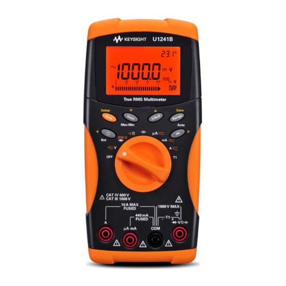
- Page 1 Keysight U1241AN Handheld Digital Multimeter User’s and Service Guide...
-
Page 2: Safety Information
FAR 27.401 or DFAR 227.7103-5 (c), as applicable in any Do not proceed beyond a WARNING technical data. notice until the indicated conditions are fully understood and met. Keysight U1241AN User’s and Service Guide... -
Page 3: Safety Symbols
In position of a bi-stable push control CAT III Category III 1000 V overvoltage Equipotentiality 1000 V protection Equipment protected throughout by CAT IV Category IV 600 V overvoltage double insulation or reinforced protection 600 V insulation Keysight U1241AN User’s and Service Guide... -
Page 4: General Safety Information
Failure to comply with these precautions or with specific warnings elsewhere in this manual violates safety standards of design, manufacture, and intended use of the instrument. Keysight Technologies assumes no liability for the customer’s failure to comply with these requirements. - Page 5 – Do not substitute parts or modify equipment to avoid the danger of introducing additional hazards. Return the product to Keysight Sales Office for service and repair to ensure the safety features are maintained. – Do not operate damaged equipment as the safety protection features built into this product may have been impaired, either through physical damage, excessive moisture, or any other reason.
-
Page 6: Measurement Category
Measurement Category The U1241AN has a safety rating of CAT III, 1000 V and CAT IV, 600 V. Measurement CAT I Measurements performed on circuits not directly connected to the AC mains. Examples are measurements on circuits not derived from the AC mains and specially protected (internal) mains-derived circuits. -
Page 7: Environmental Conditions
Altitude Edition CAT III, 1000 V/IEC 61010-1 2 Edition CAT IV, 600 V Pollution degree Pollution Degree 2 – The Keysight U1241AN complies with the following safety and EMC CAUTION requirements: – IEC 61010-1:2001 / EN61010-1:2001 – USA: ANSI/UL61010-1:2004 – Canada: CAN/CSA C22.2 No. 61010-1-04 –... -
Page 8: Regulatory Markings
NMB-001 du Canada. Communication Act of 1992. This instrument complies with the WEEE Directive (2002/96/EC) marking requirement. This affixed product label indicates that you must not discard this electrical or electronic product in domestic household waste. Keysight U1241AN User’s and Service Guide... -
Page 9: Waste Electrical And Electronic Equipment (Weee) Directive 2002/96/Ec
To return this unwanted instrument, contact your nearest Keysight Service Center, or visit http://about.keysight.com/en/companyinfo/environment/takeback.shtml for more information. Sales and Technical Support To contact Keysight for sales and technical support, refer to the support links on the following Keysight websites: – www.keysight.com/find/handhelddmm (product-specific information and support, software and documentation updates) –... -
Page 10: In This Guide
In This Guide… 1 Getting Started This chapter introduces the key features and steps to get started with the U1241AN handheld digital multimeter. This chapter also guides you through the basics of the front panel operations. 2 Features and Functions This chapter contains detailed information on how to configure connections to perform measurements using the U1241AN handheld digital multimeter. -
Page 11: Table Of Contents
..........33 Keysight U1241AN User’s and Service Guide... - Page 12 Recommended Test Equipment ....... 59 Keysight U1241AN User’s and Service Guide...
- Page 13 ......... .80 Specifications and Characteristics Keysight U1241AN User’s and Service Guide...
- Page 14 THIS PAGE HAS BEEN INTENTIONALLY LEFT BLANK. Keysight U1241AN User’s and Service Guide...
- Page 15 ......53 Figure 5-1 Annunciator display ......60 Keysight U1241AN User’s and Service Guide...
- Page 16 THIS PAGE HAS BEEN INTENTIONALLY LEFT BLANK. Keysight U1241AN User’s and Service Guide...
- Page 17 ......75 Table 5-5 Calibration error codes ......80 Keysight U1241AN User’s and Service Guide...
- Page 18 THIS PAGE HAS BEEN INTENTIONALLY LEFT BLANK. Keysight U1241AN User’s and Service Guide...
- Page 19 The Keypad and Rotary Switch at a Glance The Input Terminal at a Glance This chapter introduces the key features and steps to get started with the U1241AN handheld digital multimeter. This chapter also guides you through the basics of the front panel operations.
-
Page 20: Getting Started
Getting Started Introduction The U1241AN handheld digital multimeter key features are: – DC and AC voltage measurements – DC and AC current measurements – True RMS measurement for both AC voltage and current – Ambient temperature readout at secondary display with each measurement readout –... -
Page 21: Checking The Shipping Contents
Getting Started Checking the Shipping Contents Verify that you have received the following items with your unit. If anything is missing or damaged, please contact the nearest Keysight Sales Office. Table 1-1 List of standard items Type Items U1241AN handheld digital multimeter Four 1.5 V AAA alkaline batteries... -
Page 22: The Front Panel At A Glance
U1241AN front panel Adjusting Tilt Stand Tilt stand at 60° Tilt stand at 30° Pull the tilt stand outwards Bend the tip of the stand to its maximum reach (approximately 60°) Figure 1-2 Tilt stand positions Keysight U1241AN User’s and Service Guide... -
Page 23: The Annunciator At A Glance
Audible continuity for resistance and Secondary display (ambient temperature diode function display) Primary display Null math function Thermocouple type for temperature AC or DC measurement mode measurement Auto range Primary measurement units Diode/test mode Measurement range Keysight U1241AN User’s and Service Guide... -
Page 24: Analog Bar Graph
Each segment represents 500 or 50 counts depending on the range indicated on the peak bar graph. Table 1-3 Bar graph counts Range Counts/Segment Function Diode V, A, Ω, diode Keysight U1241AN User’s and Service Guide... -
Page 25: The Keypad And Rotary Switch At A Glance
DCA measurement 0.001 A to 10 A ACA measurement 0.500 A to 10.000 A T1 temperature –40 °C to 1000 °C DCmV measurement 0.1 mV to 100 mV ACmV measurement 0.1 mV to 1000 V Keysight U1241AN User’s and Service Guide... -
Page 26: The Input Terminal At A Glance
Starts manual data logging Press and hold for > 1 second The Input Terminal at a Glance To avoid damaging this device, do not exceed the rated input limit. WARNING Figure 1-5 U1241AN input terminals Keysight U1241AN User’s and Service Guide... - Page 27 440 mA, 30 kA/fast-acting fuse AC/DC mA AC/DC A 11A, 30 kA/fast-acting fuse Temperature –T1 1000 Vrms < 0.3A short circuit current To avoid damaging the device, do not exceed the rated input limit. WARNING Keysight U1241AN User’s and Service Guide...
- Page 28 Getting Started THIS PAGE HAS BEEN INTENTIONALLY LEFT BLANK. Keysight U1241AN User’s and Service Guide...
- Page 29 Measuring Temperature MINMAX Recording Data Hold (Trigger Hold) Refresh Hold Null (Relative) Data Logging Checking Battery Capacity Alerts and Warning During Measurement This chapter contains detailed information on how to configure connections to perform measurements using the U1241AN handheld digital multimeter.
-
Page 30: Features And Functions
Measuring DC voltage Measuring AC voltage Press to select AC voltage measurement mode. Measuring Current (> 440 mA) Measuring DC current Measuring AC current Press to select AC current measurement mode. Keysight U1241AN User’s and Service Guide... -
Page 31: Measuring Current (< 440 Ma)
The percentage scale is indicated on Press the primary display and the bar graph indicates the current value. The 25% position scale readout represents DC 5 mA at 0–20 mA and DC 8 mA at 4–20mA. Keysight U1241AN User’s and Service Guide... -
Page 32: Measuring Frequency
< 10 Ω position to enable the continuity test 10.000 kΩ < 100 Ω functions 100.00 kΩ < 1 kΩ 1.0000 MΩ < 10 kΩ 10.000 MΩ < 100 kΩ 100.00 MΩ < 1 MΩ Keysight U1241AN User’s and Service Guide... -
Page 33: Testing Diodes
Reverse bias Forward bias The multimeter can display forward bias diode of up to approximately 1.1 V. NOTE Typical forward bias diode ranges between 0.3 to 0.8 V with audible beeper sound. Keysight U1241AN User’s and Service Guide... -
Page 34: Measuring Capacitance
– Ensure the polarity is correct when measuring polarized capacitors. – For measuring small capacitances, press with the test leads open to subtract the residual capacitance of the multimeter and leads. Keysight U1241AN User’s and Service Guide... -
Page 35: Measuring Temperature
3 After a constant reading is obtained, press to set the reading as the relative reference temperature. 4 Touch the measurement surface with the thermocouple probe. 5 Read the display for the relative temperature. Keysight U1241AN User’s and Service Guide... -
Page 36: Minmax Recording
NOTE MINMAX recording mode. – If an overload is recorded, the averaging function will stop and OL will be displayed. – The auto power off feature ( ) is disabled in MINMAX recording mode. Keysight U1241AN User’s and Service Guide... -
Page 37: Data Hold (Trigger Hold)
– For resistance and diode measurements, the holding value will not be updated if the reading is in “OL” (open state). – The holding value may not be updated if the reading does not reach stable state for all measurements. Keysight U1241AN User’s and Service Guide... -
Page 38: Null (Relative)
– In DC voltage measurement, the thermal effect will influence the accuracy. Short the test leads and press once the displayed value is stable in order to zero out the offset. Keysight U1241AN User’s and Service Guide... -
Page 39: Data Logging
(Log) for more than one second to store the present value and function on the primary display to memory. 2 Press (Log) again for the next value that you want to save into memory, Figure 2-1. Keysight U1241AN User’s and Service Guide... -
Page 40: Interval Logging
Setup mode, see Figure 2-2. 3 Press (Log) for more than one second to exit this mode. When interval (automatic) logging is enabled, all keypad operation is disabled, NOTE except for the LOG function. Keysight U1241AN User’s and Service Guide... -
Page 41: Reviewing Logged Data
(View) for more than one second to exit the Log View mode. Removing Logged Data Press (Log) for more than one second at the respective Log Review mode (hand or interval) to clear all logged data in the memory. Keysight U1241AN User’s and Service Guide... -
Page 42: Checking Battery Capacity
2 The primary display illustrates the flashing bAt annunciator and the bar graph indicates the battery capacity in proportional percentage from 4.2 V (0%) to 6.0 V (100%). Figure 2-3 Battery capacity display Keysight U1241AN User’s and Service Guide... -
Page 43: Alerts And Warning During Measurement
The multimeter sounds an alerting beep when the μA/mA input terminal detects a voltage level of more than 1.6 V. The display indicates a flashing CErr annunciator until the test lead is removed from the μA/mA input terminal. Keysight U1241AN User’s and Service Guide... - Page 44 Features and Functions THIS PAGE HAS BEEN INTENTIONALLY LEFT BLANK. Keysight U1241AN User’s and Service Guide...
-
Page 45: Default Settings Configurations
Keysight U1241AN Handheld Digital Multimeter User’s and Service Guide Default Settings Configurations Setting Configurations This chapter describes on how to change and configure the default settings of the U1241AN handheld digital multimeter including data logging and other features. -
Page 46: Setting Configurations
3 Press (Save) to save the changes. These parameters remain in the non-volatile memory. 4 Press and hold (Setup) for more than one second to exit Setup mode. Keysight U1241AN User’s and Service Guide... -
Page 47: Available Setting Options In Setup Mode
Disables auto turn-off for backlight display Default AC or DC for Defines the preferred setup of AC or DC for voltage voltage and current dC, AC and current measurement once multimeter is measurements turned on. Keysight U1241AN User’s and Service Guide... - Page 48 [a] To activate the multimeter after it has auto power off, press any button to resume back to respective functional mode. [b] To view Temperature (t P) menu, press for more than one second. Keysight U1241AN User’s and Service Guide...
- Page 49 Repair or service which are not covered in this manual should only be performed by qualified service personnel. Please return to Keysight for product exchange if the product fails within the warranty period.
-
Page 50: Service And Maintenance
2 Unscrew the battery cover, notice the screw may not remove as loosed. 3 Lift and remove the battery cover to the direction of screw. 4 Replace the specified batteries and ensure the correct polarity of batteries. Keysight U1241AN User’s and Service Guide... - Page 51 Service and Maintenance 5 Reverse the procedures of opening the cover to close the battery cover. Battery Types ANSI/NEDA Alkaline LR03 Zinc Chloride Battery cover screw Figure 4-1 Battery replacement Keysight U1241AN User’s and Service Guide...
-
Page 52: Fuse Replacement
6 Gently remove the defective Fuse 2 by prying one end of the fuse loose and removing it out of the fuse bracket, see Figure 4-3 on page 53. 7 Replace a new fuse of the same size and rating into the center of the fuse holder. Keysight U1241AN User’s and Service Guide... - Page 53 8 Ensure that the rotary switch position is aligned with the align marking on the top case and circuit board switch stay on the OFF position. 9 Then refasten the circuit board and the bottom cover respectively. Keysight U1241AN User’s and Service Guide...
-
Page 54: Troubleshooting
Battery cover U1241-44701 Multimeter stand U1241-60002 LCD display 2110-1400 Fast blow fuse 1000 V, 0.44 A (10 mm x 35 mm) 2110-1402 Fast blow fuse 1000 V, 11 A (10 mm x 35 mm) Keysight U1241AN User’s and Service Guide... -
Page 55: Returning Instrument For Service
You are recommended to use the original shipping material or order materials from a Keysight Technologies Sales Office. If both options are not available, place 8 cm to 10 cm (3 inches to 4 inches) of shock-absorbing and static-free packaging material around the instrument to avoid movement during shipping. - Page 56 Service and Maintenance THIS PAGE HAS BEEN INTENTIONALLY LEFT BLANK. Keysight U1241AN User’s and Service Guide...
-
Page 57: Performance Tests And Calibration
Keysight U1241AN Handheld Digital Multimeter User’s and Service Guide Performance Tests and Calibration Calibration Overview Recommended Test Equipment Basic Operating Test Calibration Process Test Considerations Performance Verification Tests Calibration Security Adjustment Considerations Calibration Adjustments Calibration Count Calibration Errors This chapter contains procedures of performance verification tests and calibration adjustments. -
Page 58: Calibration Overview
Whatever calibration interval you select, Keysight recommends that complete re-adjustment should always be performed at the calibration interval. This will assure that the U1241AN will remain within specification for the next calibration interval. This criteria for re-adjustment provides the best long–term stability. -
Page 59: Recommended Test Equipment
Diode Fluke 5520A < 1/5 instrument 1 year specifications Fluke 5520A < 1/5 instrument 1 year specifications Temperature TM Electronics KMPC1MP — (K-Type thermocouple extension) Short Pomona MDP-S < 1/5 instrument 1 year specifications Keysight U1241AN User’s and Service Guide... -
Page 60: Basic Operating Test
To view all segments of the display, press and hold the button while turning the rotary switch from OFF to any non-OFF position. Compare the display with the Figure 5-1. Figure 5-1 Annunciator display Keysight U1241AN User’s and Service Guide... -
Page 61: Input-A Terminal Test
1.6 V. The display indicates a flashing CErr annunciator until the test lead is removed from the μA/mA input terminal. The alerting beep will continue to function even if the beep function is disabled. NOTE Keysight U1241AN User’s and Service Guide... -
Page 62: Calibration Process
6 Secure the multimeter against unauthorized calibration, see “Exiting Adjustment Mode” on page 78. Ensure that the multimeter has quit the Adjustment Mode and turned off. 7 Record the new security code and calibration count in the multimeter’s maintenance records. Keysight U1241AN User’s and Service Guide... -
Page 63: Test Considerations
During DC voltage, DC current, and resistance gain verification measurements, ensure that the calibrator's “0” output is correct. It is recommended to set the offset for each range of the measuring function being verified. Keysight U1241AN User’s and Service Guide... -
Page 64: Input Connections
‘guard band’, using not more than 80% of the specifications, as the verification limits. Users are highly recommended to read the “Test Considerations” on page 63 NOTE before performing performance verification tests. Keysight U1241AN User’s and Service Guide... - Page 65 1.000 V, 1000 Hz ± 400 mHz Press to go to frequency mode 10 kHz 1.000 V, 2 kHz ± 1.6 Hz Diode 1.000 V ± 5 mV Turn the rotary switch to position Keysight U1241AN User’s and Service Guide...
- Page 66 Turn the rotary switch to position 10.000 A 10 A ± 102 mA 10.000 A , 2 kHz Press to go to function 100 mV 100.00 mV ± 0.11 mV Turn the rotary switch to position Keysight U1241AN User’s and Service Guide...
- Page 67 (without internal ambient compensation 0 ºC). If both calibrator and multimeter are set with internal reference (with internal ambient compensation), deviation may be present between the readings of the calibrator and multimeter. Keysight U1241AN User’s and Service Guide...
-
Page 68: Calibration Security
5 If the correct security code is entered, the secondary display will show “PAS”. If an invalid code is entered, the multimeter will shows error code “E02” on the secondary display for approximately 3 seconds before returning to the Calibration Security entry mode. Keysight U1241AN User’s and Service Guide... - Page 69 PASS. If the new code failed to save, the multimeter will shows error code E07 on the secondary display for approximately 3 seconds before returning to the Calibration Security Code setting mode. Keysight U1241AN User’s and Service Guide...
-
Page 70: Using The Front Panel For Adjustments
“Unsecuring the Multimeter for Calibration” page 68 or “Unsecuring the multimeter without the security code” on page 70. Once the multimeter has been unsecured, the reference value will be indicated on the primary display. Keysight U1241AN User’s and Service Guide... -
Page 71: Adjustment Considerations
It is recommended to wait for one minute before start performing the calibration. 4 During ambient temperature adjustment, ensure that the multimeter has been turned on for at least one hour with K-type thermocouple connected between the multimeter and calibration source. Keysight U1241AN User’s and Service Guide... -
Page 72: Valid Adjustment Input Values
0.9 to 1.1 x full scale 1000 μA, 10000 μA 0.9 to 1.1 x full scale 100 mA, 1000 mA 0.9 to 1.1 x full scale 10 A 0.9 to 1.1 x full scale Keysight U1241AN User’s and Service Guide... -
Page 73: Calibration Adjustments
5 Apply the input signal as shown in the Input Reference Value column of the Table 5-3. The bar graph will display the input reading. There is no bar graph display for temperature adjustment. Keysight U1241AN User’s and Service Guide... - Page 74 Table 5-3. Repeat step 3 step 8 for each adjustment point shown in the calibration adjustment, see Table 5-4. 10 Verify the adjustments using the “Performance Verification Tests” on page 64. Keysight U1241AN User’s and Service Guide...
-
Page 75: Calibration Adjustments
50.0 V 1000 V 1000 V, 70 Hz 1000.0 V 1000V, 1 kHz 1000.0 V Dual banana plug with SHrt Short copper wires short Turn the rotary switch to position between two terminals 1.000 V Keysight U1241AN User’s and Service Guide... - Page 76 10.000 mF Input terminals open (remove all test leads and Open oPEn shorting plugs from input terminals) Turn the rotary switch to position 1000 μA 1000 μA 1000.0 μA 10000 μA 10000 μA 10000 μA Keysight U1241AN User’s and Service Guide...
- Page 77 Caution: Connect the calibrator to the mul timeter's “A” and “COM” terminal before applying 10 A Input terminals open (remove all test leads and Open oPEn shorting plugs from input Turn the rotary switch to position terminals) 10 A 10 A 10.000 A Keysight U1241AN User’s and Service Guide...
-
Page 78: Exiting Adjustment Mode
2 Record the new Calibration Count, see “Calibration Count” on page 79. 3 Press simultaneously to exit the Adjustment Mode. Power off and on the multimeter to return to normal measurement mode and secured. Keysight U1241AN User’s and Service Guide... -
Page 79: Calibration Count
2 Take note of the calibration count to keep track of the number of calibration counts that has been performed. 3 Press and hold for more than one second to exit the calibration count mode. Keysight U1241AN User’s and Service Guide... -
Page 80: Calibration Errors
Calibration error: Invalid secure code Calibration error: Invalid serial number code Calibration error: Calibration aborted Calibration error: Value out of range Calibration error: Signal measurement out of range Calibration error: Frequency out of range EEPROM write failure Keysight U1241AN User’s and Service Guide... -
Page 81: Specifications And Characteristics
Keysight U1241AN Handheld Digital Multimeter User’s and Service Guide Specifications and Characteristics For the characteristics and specifications of the U1241AN Handheld Digital Multimeter, refer to the datasheet at http://literature.cdn.keysight.com/litweb/ pdf/5989-7040EN.pdf. - Page 82 Specifications and Characteristics THIS PAGE HAS BEEN INTENTIONALLY LEFT BLANK. Keysight U1241AN User’s and Service Guide...
- Page 83 J-type condensation readings configuration recording connections refresh hold terminal key features regulatory container keypad relative K-type removing replacement residual returning data logging reviewing hold interval rotary switch logging manual display annunciator backlight Keysight U1241AN User’s and Service Guide...
- Page 84 True-RMS warm-up warning WEEE Keysight U1241AN User’s and Service Guide...
- Page 85 This information is subject to change without notice. Always refer to the Keysight website for the latest revision. © Keysight Technologies 2008 - 2016 Edition 9, July 30, 2016 Printed in Malaysia *U1241-90038* U1241-90038 www.keysight.com...
Need help?
Do you have a question about the U1241AN and is the answer not in the manual?
Questions and answers