Keysight U1231A Quick Start Manual
Handheld
Hide thumbs
Also See for U1231A:
- Quick start manual (177 pages) ,
- User manual (123 pages) ,
- Quick start manual (18 pages)
Table of Contents
Advertisement
Quick Links
Download this manual
See also:
User Manual
Advertisement
Table of Contents

Subscribe to Our Youtube Channel
Related Manuals for Keysight U1231A


Summary of Contents for Keysight U1231A
- Page 1 Keysight U1231A/U1232A/ U1233A Handheld Multimeter Quick Start Guide...
- Page 3 Printed copy of the U1231A/U1232A/U1233A Quick Start Guide If any item is missing or damaged, keep the shipping materials and contact the nearest Keysight Sales Office. The descriptions and instructions in this guide apply to the NO TE U1231A, U1232A, and U1233A handheld multimeters.
-
Page 4: Install The Batteries
To use this feature, you will need a PC running a Windows operating system, an IR-USB cable (U1173A, purchased sepa- rately), and the Keysight GUI Data Logger Software. The Keysight GUI Data Logger software is downloadable for free from www.keysight.com/find/hhTechLib. U1231A/U1232A/U1233A Quick Start Guide... -
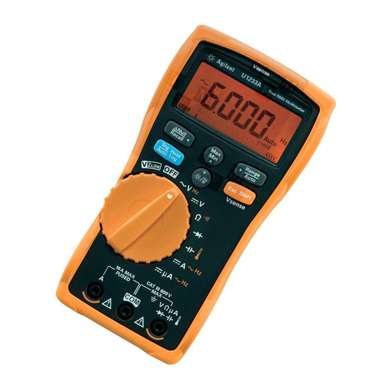
Page 5: The Multimeter At A Glance
U1231A/U1232A/U1233A Handheld Multimeter The Multimeter at a Glance The Multimeter at a Glance Vsense indicator (U1233A only) Display screen Keypad Rotary switch Input terminals LED flashlight Test lead/probe holders IR communication port Battery cover Tilt stand U1231A/U1232A/U1233A Quick Start Guide... -
Page 6: Understanding The Rotary Switch
Remove the test leads from the measuring source or WA RN ING target before changing the rotary switch position. Refer to the U1231A/U1232A/U1233A User’s Guide for a complete list and description of all rotary switch labels for each separate multimeter model. -
Page 7: Understanding The Keypad
(icons printed in non-contact voltage detector orange) functions (Vsense). Understanding the Input Terminals Rotary position for Input terminals Overload protection U1232A and U1233A 600 Vrms 600 Vrms for short circuit <0.3 A 11 A/1000 V, fast-acting fuse U1231A/U1232A/U1233A Quick Start Guide... -
Page 8: Non-Contact Voltage Detector (Vsense)
The Vsense detector may be affected by differences in socket design, insulation thickness, and insulation type. Voltage source > 1 s Press to change the Vsense detector’s sensitivity from NO TE Hi.SE (high sensitivity) to Lo.SE (low sensitivity). U1231A/U1232A/U1233A Quick Start Guide... -
Page 9: Performing Measurements
U1231A/U1232A/U1233A Handheld Multimeter Performing Measurements Performing Measurements AC voltage measurements Voltage source DC voltage measurement Voltage source U1231A/U1232A/U1233A Quick Start Guide... -
Page 10: Resistance Measurement
U1231A/U1232A/U1233A Handheld Multimeter Performing Measurements Resistance measurement Resistor Continuity test (open) (closed ) Press again to switch between testing for shorted ( ) or open ( ) contacts. U1231A/U1232A/U1233A Quick Start Guide... - Page 11 U1231A/U1232A/U1233A Handheld Multimeter Performing Measurements Forward bias diode test Forward bias diode Reverse bias diode test Reverse bias diode U1231A/U1232A/U1233A Quick Start Guide...
-
Page 12: Capacitance Measurement
DC V function to confirm that the capacitor is fully dis- charged. Capacitance is shown on the bottom left of the display when the capaci- NO TE tor is charging, and is shown when the capacitor is dis- charging. U1231A/U1232A/U1233A Quick Start Guide... -
Page 13: Temperature Measurement
• The multimeter uses a type-K thermocouple probe (U1186A, NO TE purchased separately) for measuring temperature. • For auxiliary temperature measurement on the U1231A and U1232A, a temperature module such as the U1586B (purchased separately) is required. U1231A/U1232A/U1233A Quick Start Guide... -
Page 14: Current Measurement (Up To A)
Current measurement (up to A) Always use the proper function. range, and terminals for WA RN ING current measurements. Set the positive input terminal to μ the A terminal for currents above 600 Voltage source LOAD Voltage source LOAD U1231A/U1232A/U1233A Quick Start Guide... -
Page 15: Current Measurement
Current measurement (up to Always use the proper function. range, and terminals for WA RN ING current measurements. Set the positive input terminal to μ μ A terminal for currents below 600 Voltage source LOAD Voltage source LOAD U1231A/U1232A/U1233A Quick Start Guide... -
Page 16: Vz Low Measurement
Energized wiring Adjacent unused wiring Ghost voltages can be caused by capacitive coupling between NO TE energized wiring and adjacent unused wiring. Use the VZ function to eliminate ghost or induced voltages in your mea- surements. U1231A/U1232A/U1233A Quick Start Guide... -
Page 17: Safety Notices
• China Call Center: 800-810-0189 • Europe Call Center: 31-20-547-2111 • Japan Call Center: (81) 426-56-7832 For other countries, contact your country’s Keysight support organization. A list of contact information for other countries is available on the Keysight Web site: www.keysight.com/find/assist Safety Notices... - Page 18 This information is subject to change without notice. © Keysight Technologies 2011 - 2014 Edition 3, August 2014 *U1231-90023* U1231-90023 www.keysight.com...
Need help?
Do you have a question about the U1231A and is the answer not in the manual?
Questions and answers