Table of Contents
Advertisement
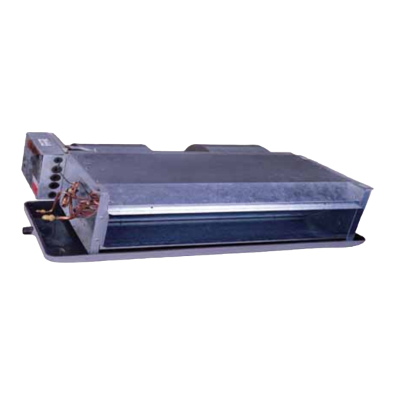
Indoor Units
EDS25
EDS35
EDS52
EDS73
EDS100
EDS120
EDS25X2
EDS35X2
EDS52X2
EDS25X2+EDS35
EDS25X2+EDS52
EDS25+EDS35+EDS52
EDS35X3
REFRIGERANT
R22
REV:
0
EDS Series
Outdoor Units
GCN9
GCN12
ONG3-18
GCZ22
GC10-34
GC45
GC9+9
GC12+12
GC17+17
GC9+9+12
GC9+9+17
GC9+12+17
GC12+12+12
COOLING ONLY
COOLING ONLY WITH HEATER
HEAT PUMP
HEAT PUMP WITH HEATER
FEB 2009
Advertisement
Table of Contents

Related Manuals for Airwell EDS25


Summary of Contents for Airwell EDS25
- Page 1 EDS Series Indoor Units Outdoor Units EDS25 GCN9 EDS35 GCN12 EDS52 ONG3-18 EDS73 GCZ22 EDS100 GC10-34 EDS120 GC45 EDS25X2 GC9+9 EDS35X2 GC12+12 EDS52X2 GC17+17 EDS25X2+EDS35 GC9+9+12 EDS25X2+EDS52 GC9+9+17 EDS25+EDS35+EDS52 GC9+12+17 EDS35X3 GC12+12+12 COOLING ONLY REFRIGERANT COOLING ONLY WITH HEATER HEAT PUMP...
- Page 2 LIST OF EFFECTIVE PAGES LIST OF EFFECTIVE PAGES Note: Changes in the pages are indicated by a “Revision#” in the footer of each effected page (when none indicates no changes in the relevant page). All pages in the following list represent effected/ non effected pages divided by chapters.
-
Page 3: Table Of Contents
TABLE OF CONTENTS Table of Contents INTRODUCTION ....................1-1 PRODUCT DATA SHEET ..................2-1 RATING CONDITIONS ..................3-1 OUTLINE DIMENSIONS ..................4-1 PERFORMANCE DATA & PRESSURE CURVES ..........5-1 SOUND LEVEL CHARACTERISTICS ..............6-1 ELECTRICAL DATA....................7-1 WIRING DIAGRAMS .....................8-1 ELECTRICAL CONNECTIONS................9-1 10. REFRIGERATION DIAGRAMS ................10-1 11. TUBING CONNECTIONS..................11-1 12. -
Page 4: Introduction
EDS73D/GCZ R22 RC; EDS100D/GC10-34 R22 RC;EDS120D/GC45 R22 RC; Dual: EDS25x2 A(B,D,H)/GC9+9 ST(RC); EDS35x2 A(B,D,H)/GC12+12 ST(RC); EDS52x2 A(B,D,H)/GC17+17 ST(RC); Trio: EDS25x2+35A(B,D,H)/GC9+9+12 ST(RC);EDS25x2+52A(B,D,H)/GC9+9+17 ST(RC); EDS25+35+52A(B,D,H)/GC9+12+17 ST(RC);EDS35x3A(B,D,H)/GC12+12+12 ST(RC) Main Features The EDS namely: R22 models. Microprocessor control. Infrared remote control with liquid crystal display. -
Page 5: Indoor Unit
INTRODUCTION Indoor Unit The indoor unit is ductable pressurized residential and commercials applications. It includes: Casing with air inlet and outlet grills. Bended coil with treated aluminum ns. Multi-speed motor with internal protection Advanced electronic control box assembly Interconnecting wiring terminal block Mounting plate Filtration Easily accessible, and re-usable pre... - Page 6 Matching Table Matching Table 1.9.1 Indoor unit Type Outdoor unit Unit 1 Unit 2 Unit 3 EDS73 EDS100 EDS120 GCN 9 EDS25 GCN 12 EDS35 ONG 3-18 EDS52 Single GCZ 22 EDS73 GC 10-34 EDS100 GC 45 EDS120 GC9+9...
-
Page 7: Product Data Sheet
PRODUCT DATA SHEET PRODUCT DATA SHEET Model Indoor Unit EDS 25 Model Outdoor Unit GCN 9 Installation Method of Pipe Flared Characteristics Units Cooling only Cooling Heating Btu/hr 9380 9380 9550 Capacity (4) 2.75 2.80 2.75 Power input (4) 0.932 0.80 0.932 EER (Cooling) or COP(Heating) (4) - Page 8 PRODUCT DATA SHEET Model Indoor Unit EDS 35 Model Outdoor Unit GCN12 Installation Method of Pipe Flared Characteristics Cooling Heating Units Cooling only 12620 12110 Btu/hr 12620 Capacity (4) 3.70 3.55 3.70 Power input (4) 1.175 1.175 0.98 EER (Cooling) or COP(Heating) (4) 3.15 3.15 3.62...
- Page 9 PRODUCT DATA SHEET Model Indoor Unit EDS 52 Model Outdoor Unit ONG3-17 Installation Method of Pipe Flared Characteristics Cooling Heating Units Cooling only 19790 18940 Btu/hr 19790 Capacity (4) 5.80 5.80 5.55 Power input (4) 1.92 1.92 1.61 EER (Cooling) or COP(Heating) (4) 3.02 3.45 3.02...
- Page 10 PRODUCT DATA SHEET Model Indoor Unit EDS 73 Model Outdoor Unit GC-22 Installation Method of Pipe Flared Characteristics Cooling Heating Units Cooling only 23710 25250 Btu/hr 23710 Capacity (4) 6.95 6.95 7.40 Power input (4) 2.31 2.05 2.31 EER (Cooling) or COP(Heating) (4) 3.01 3.61 3.01...
- Page 11 PRODUCT DATA SHEET Model Indoor Unit EDS 100 Model Outdoor Unit GC 10-34 Installation Method of Pipe Flared Characteristics Cooling Heating Units 33440 37530 Btu/hr Capacity (4) 9.80 11.00 Power input (4) 3.50 EER (Cooling) or COP(Heating) (4) 2.51 3.14 Energy efficiency class 380-415 Power supply...
- Page 12 PRODUCT DATA SHEET Model Indoor Unit EDS 120 Model Outdoor Unit GC 45 Installation Method of Pipe Flared Characteristics Units Cooling Heating 43670 54590 Btu/hr Capacity (4) 12.80 16.00 Power input (4) 4.56 4.98 EER (Cooling) or COP(Heating) (4) 2.81 3.21 Energy efficiency class 380-415...
-
Page 13: Rating Conditions
RATING CONDITIONS RATING CONDITIONS Standard conditions in accordance with ISO 5151, ISO 13253 (for ducted units) and EN 14511. Cooling: Indoor: C DB 19 C WB Outdoor: 35 C DB Heating: Indoor: C DB Outdoor: 7 C DB 6 C WB Operating Limits 3.1.1 Indoor... -
Page 14: Outline Dimensions
EDS 35 EDS 100 EDS 52 EDS 120 Hanging hole Electrical Box Hanging hole Water Drain Port OD G 3/4" Quantity Dimensions(mm) Model Moter EDS25 EDS35 EDS52 1050 EDS73 1150 1200 1335 1203 EDS100 1320 1370 1505 1373 EDS120 1570... - Page 15 OUTLINE DIMENSIONS OUTDOOR MODEL GCN 9 GCN 12 OUTDOOR MODEL ONG3-17 Unit mm Service Manual - EDS Revision 0...
- Page 16 OUTLINE DIMENSIONS OUTDOOR MODEL GC 22 GC 9+9 GC 12+12 Different configuration in different model Unit mm OUTDOOR MODEL GC 10-34 GC45 1270 Unit mm Service Manual - EDS Revision 0...
- Page 17 OUTLINE DIMENSIONS OUTDOOR MODEL GC 17+17 GC 9+9+12 GC 9+9+17 GC 9+12+17 GC 12+12+12 1270 Different configuration in different model 187.5 80.8 Unit mm Service Manual - EDS Revision 0...
- Page 18 Cooling Capacity(KW) EDS25H / GCN9 R22 Entering Air DB Data Entering Air WB/DB ID Coil( OD Coil( 15/21 17/24 19/27 21/29 23/32 2.72 2.88 3.02 3.15 3.26 2.19 2.33 2.45 2.40 2.44 0.70 0.70 0.70 0.70 0.70 2.70 2.86 2.99 3.12 3.23 1.92...
- Page 19 EDS25H / GCN9 R22 Heating Capacity (KW) ENTERING AIR DB ID COIL( ENTERING WB OD COIL( 1.50 0.72 1.44 0.77 1.38 0.81 1.61 0.74 1.55 0.78 1.50 0.82 1.71 0.75 1.65 0.79 1.60 0.84 2.08 0.78 2.00 0.83 1.91 0.88 2.94 0.84 2.85...
- Page 20 Cooling Capacity(KW) EDS35H / GCN12 R22 Entering Air DB Data Entering Air WB/DB ID Coil( OD Coil( 15/21 17/24 19/27 21/29 23/32 3.56 3.77 3.94 4.12 4.26 3.01 3.19 3.36 3.28 3.34 0.85 0.85 0.85 0.86 0.86 3.52 3.73 3.91 4.08 4.22 2.51...
- Page 21 EDS35H / GCN12 R22 Heating Capacity (KW) ENTERING AIR DB ID COIL( ENTERING WB OD COIL( 1.81 0.81 1.74 0.86 1.67 0.90 1.95 0.83 1.88 0.87 1.81 0.92 2.07 0.84 2.00 0.89 1.93 0.94 2.52 0.88 2.42 0.93 2.31 0.99 3.55 0.94 3.45...
- Page 22 Cooling Capacity(KW) EDS52H /ONG3-17 R22 Entering Air DB Data Entering Air WB/DB ID Coil( OD Coil( 15/21 17/24 19/27 21/29 23/32 5.77 6.11 6.40 6.68 6.91 4.56 4.84 5.10 4.98 5.07 1.46 1.46 1.46 1.47 1.47 5.72 6.06 6.34 6.62 6.85 4.08 4.33...
- Page 23 EDS52H /ONG3-17 R22 Heating Capacity (KW) ENTERING AIR DB ID COIL( ENTERING WB OD COIL( 2.81 1.33 2.70 1.41 2.59 1.49 3.02 1.36 2.92 1.44 2.81 1.51 3.21 1.38 3.10 1.46 3.00 1.54 3.91 1.44 3.75 1.54 3.58 1.63 5.51 1.55 5.35 1.66...
- Page 24 Cooling Capacity(KW) EDS73H /GCZ22 R22 Entering Air DB Data Entering Air WB/DB ID Coil( OD Coil( 15/21 17/24 19/27 21/29 23/32 6.57 6.96 7.28 7.60 7.86 5.34 5.66 5.96 5.83 5.93 1.70 1.71 1.71 1.72 1.72 6.50 6.89 7.21 7.53 7.79 4.64 4.93...
- Page 25 EDS73H /GCZ22 R22 Heating Capacity (KW) ENTERING AIR DB ID COIL( ENTERING WB OD COIL( 3.61 1.69 3.47 1.80 3.34 1.89 3.89 1.73 3.75 1.83 3.61 1.92 4.13 1.75 3.99 1.86 3.85 1.96 5.02 1.84 4.82 1.95 4.61 2.07 7.09 1.97 6.88 2.11...
- Page 26 Cooling Capacity(KW) EDS100H /GC10-34 R22 Entering Air DB Data Entering Air WB/DB ID Coil( OD Coil( 15/21 17/24 19/27 21/29 23/32 9.68 10.25 10.72 11.20 11.58 7.19 7.63 8.04 7.85 7.99 2.75 2.76 2.76 2.78 2.79 9.58 10.15 10.63 11.10 11.48 6.83 7.26...
- Page 27 EDS100H /GC10-34 R22 Heating Capacity (KW) ENTERING AIR DB ID COIL( ENTERING WB OD COIL( 5.82 2.81 5.60 2.99 5.38 3.14 6.27 2.88 6.04 3.04 5.82 3.20 6.65 2.91 6.43 3.09 6.21 3.26 8.10 3.05 7.76 3.25 7.43 3.44 11.42 3.28 11.09 3.51...
- Page 28 Cooling Capacity(KW) EDS120H /GC45 R22 Entering Air DB Data Entering Air WB/DB ID Coil( OD Coil( 15/21 17/24 19/27 21/29 23/32 11.88 12.58 13.16 13.75 14.21 7.86 8.33 8.78 8.58 8.73 3.39 3.40 3.40 3.42 3.43 11.77 12.47 13.05 13.63 14.10 8.39 8.91...
- Page 29 EDS120H /GC45 R22 Heating Capacity (KW) ENTERING AIR DB ID COIL( ENTERING WB OD COIL( 7.60 4.02 7.31 4.28 7.02 4.49 8.18 4.12 7.89 4.34 7.60 4.58 8.68 4.17 8.39 4.42 8.10 4.67 10.56 4.37 10.13 4.64 9.69 4.92 14.90 4.69 14.47 5.02...
- Page 30 Outdoor Unit Noise Data Report - Fix RPM Model: GCN9RC(R22) Type: PILOT Outdoor Background Noise,dB(A): 25.1 Outdoor Octave Band Sound Pressure Level, dB Outdooor Drawing of microphon position Outdoor Octave Cooling Heating Band Unit Mic. 1000 2000 4000 Ground 8000 50.5 Outdoor Sound Pressure dB(A)
- Page 31 Outdoor Unit Noise Data Report - Fix RPM Model: GCN12RC(R22) Type: Pilot Outdoor Background Noise,dB(A): 25.1 Outdoor Octave Band Sound Pressure Level, dB Outdooor Drawing of microphon position Outdoor Octave Cooling Heating Band Unit Mic. 1000 2000 4000 Ground 8000 54.9 Outdoor Sound Pressure dB(A)
- Page 32 Outdoor Unit Noise Data Report - Fix RPM Model: ONG3-17 Type: Polit Outdoor Background Noise,dB(A): 25.1 Outdoor Octave Band Sound Pressure Level, dB Outdooor Drawing of microphone position Outdoor Octave Cooling Heating Band Unit Mic. 1000 2000 4000 Ground 8000 53.3 Outdoor Sound Pressure level ,dB(A)
- Page 33 Outdoor Unit Noise Data Report - Fix RPM Model: GC22RC(R22) Type: AUDIT Outdoor Background Noise,dB(A): 24.1 Outdoor Octave Band Sound Pressure Level, dB Outdooor Drawing of microphon position Outdoor Octave Cooling Heating Band Unit Mic. 1000 2000 4000 Ground 8000 58.2 Outdoor Sound Pressure dB(A)
- Page 34 Noise Data Report 2009-2-13 Cooling/Heating Outdoor Unit Noise Data Report - Fix RPM Model: GC34RC(R22) Type: AUDIT Outdoor Background Noise,dB(A): 23.9 Outdoor Octave Band Sound Pressure Level, dB Outdooor Drawing of microphon position Outdoor Octave Cooling Heating Band Unit Mic. 1000 2000 4000...
- Page 35 Noise Data Report 2009-2-13 Cooling/Heating Outdoor Unit Noise Data Report - Fix RPM Model: GC45RC(R22) Type: AUDIT Outdoor Background Noise,dB(A): 23.9 Outdoor Octave Band Sound Pressure Level, dB Outdooor Drawing of microphon position Outdoor Octave Cooling Heating Band Unit Mic. 1000 2000 4000...
-
Page 36: Electrical Data
ELECTRICAL DATA ELECTRICAL DATA MODEL EDS 25/ GCN9 EDS 35/ GCN12 EDS 52/ ONG3-17 EDS 73/ G 22 Indoor Unit EDS25 EDS35 EDS52 EDS73 Model Outdoor Unit GCN9 GCN12 ONG3-17 Power Supply 1N~230V-50Hz Max. Current 12.9 18.7 Power Supply 3G, 1.0 3G, 1.5... - Page 37 1. If there is a additional electric-heater, the cable must be thicken one grade. 2. Use supply wire sizes as per local electrical codes and regulations. Model: EDS 52+52 / GC17+17 EDS25X2+EDS35 / GC9+9+12 EDS25 2+EDS52 / GC9+9+17 EDS25+EDS35+EDS52/ GC9+12+17 EDS35X3 / GC12+12+12 Indoor Unit 2 EDS52...
-
Page 38: Wiring Diagrams
WIRING DIAGRAMS WIRING DIAGRAMS Indoor Unit : EDS25 EDS35 EDS52 EDS73 Service Manual - EDS Revision 0... - Page 39 WIRING DIAGRAMS Indoor Unit : EDS100 EDS120 Service Manual - EDS Revision 0...
- Page 40 WIRING DIAGRAMS Outdoor unit : GCN9 GCN12 Service Manual - EDS Revision 0...
- Page 41 WIRING DIAGRAMS Outdoor unit : GC10-34 GC45 Service Manual - EDS Revision 0...
- Page 42 WIRING DIAGRAMS Outdoor unit : ONG3-17 Service Manual - EDS Revision 0...
- Page 43 WIRING DIAGRAMS Outdoor unit : GCZ22 Service Manual - EDS Revision 0...
-
Page 44: Electrical Connections
ELECTRICAL CONNECTIONS ELECTRICAL CONNECTIONS Model: EDS25/GCN9 EDS35/GCN12 EDS52/ONG3-17 EDS73/GCZ22 Service Manual - EDS Revision 0... - Page 45 ELECTRICAL CONNECTIONS Model: EDS100/GC10-34 EDS120/GC45 Indoor Unit Outdoor Unit sensor connection wires (only for heatpump) connection cable Electrical protection to be provided during installation Power Supply 400V/3N~/50Hz Service Manual - EDS Revision 0...
- Page 46 ELECTRICAL CONNECTIONS Model: 2xEDS25/GC9+9 2xEDS/GC12+12 Cable C Power supply 230V 50Hz Electrical protection to be provided during installation Outdoor Unit Only for heatpump unit ------- 4.7k NOTICE: Defrost cable have to be disabled and resistors have to be used in two indoor units when unit is cooling only model.
- Page 47 ELECTRICAL CONNECTIONS Model: EDS 52+52 / GC 17+17 EDS 25x2+EDS 35 / GC 9+9+12 EDS 25x2+EDS 52 / GC 9+9+17 EDS 25+EDS 35+EDS52 / GC 9+12+17 EDS 35x3 / GC 12+12+12 ID 1 ID 2 ID 3 Electrical protection to be provided during installation Outdoor Unit 400V/3Ph/50Hz...
-
Page 48: Refrigeration Diagrams
REFRIGERATION DIAGRAMS REFRIGERATION DIAGRAMS 10.1 Heat Pump Models 10.1.1 EDS25H / GCN 9 RC EDS35H / GCN 12 RC EDS52H / ONG3-18 RC EDS73H/GCZ22 RC EDS100H/GC10-34 RC EDS120H/GC45 RC OUTDOOR UNIT INDOOR UNIT Service port Sensor Sensor Flared Valves connection Reverse valve Capillary... - Page 49 REFRIGERATION DIAGRAMS 10.2 Cooling Only Models 10.2.1 EDS25A/GCN9 ST EDS35A/GCN12 ST EDS52A/ONG3-18 ST EDS73A/GCZ22 ST EDS100A/GC10-34 ST EDS120A/GC45 ST Service Manual - EDS Revision 0 10-2...
-
Page 50: Tubing Connections
TUBING CONNECTIONS TUBING CONNECTIONS TUBE (Inch) ¼” ” ½” ” ¾” TORQUE (Nm) Flare Nuts 11-13 40-45 60-65 70-75 80-85 Valve Cap 13-20 13-20 18-25 18-25 40-50 Service Port Cap 11-13 11-13 11-13 11-13 11-13 Valve Protection Cap-end Refrigerant Valve Port (use Allen wrench to open/close) Valve Protection Cap Refrigerant Valve Service Port Cap... -
Page 51: Control System
CONTROL SYSTEM CONTROL SYSTEM EDS Series 12.1 Electronic Control 12.1.1 Introduction The electronic control information is designed for service applications, and is common to the following groups of air-conditioners: ST/ RC group -Cooling only / cooling and heating by heat pump. SH group -Cooling and heating by heat pump and supplementary heater. - Page 52 CONTROL SYSTEM 12.2 Legend - Alternate Current - Air-Conditioner - ON or OFF status CLOCK - ON/OFF Operation Input, (dry contact) COMP - Compressor - Central Processing Unit ELUM - Extended Louver Upward Movement (Software Jumper) E²PROM, EEP - Erase Enable Programmable Read Only Memory - Heating Element - High Pressure Control - Hardware...
-
Page 53: General Functions
CONTROL SYSTEM 12.3 General functions 12.3.1 COMP operation For each Mode including POWER OFF & SB, a Min time delay of 3 min before COMP restarting, excluding DEICING Mode The Min operation time of COMP under different operating conditions is Min operation time of Operation Mode COMP... - Page 54 CONTROL SYSTEM 12.3.5 Protections High pressure protection is applicable to all operating modes. Deicing control is valid in Heat and Auto Heat Mode only. Defrosting control is valid in Dry, Cool, Heat and Auto Modes. No reset after protection modes. 12.3.6 Thermistors operation Return air Temp.
- Page 55 CONTROL SYSTEM 12.3.6.2 Handling the thermistor faults in a COMP unit ICT/OCT thermistor is disconnected or shorted - The invalid thermistor temperature is replaced by 43 c, so that the unit can continue the normal operation. All protections related to that faulty thermistor will be disabled.
- Page 56 CONTROL SYSTEM 12.4 Cooling Mode - General Room Temperature, RT, is detected by RAT in normal operation, or RCT (R/C sensor) in I-FEEL mode. The resolution of RT is 1 RT is activating COMP/WVL if (RT > SPT), and RT is stopping COMP/WVL if (RT =< SPT). Indoor Coil Temp is detected by ICT (RT2).
- Page 57 CONTROL SYSTEM 12.4.1 Cooling Mode: Cool, Auto (at Cooling) Temp: Selected desired temperature. Fan: HIGH, MED, LOW Timer: Any I Feel: On or Off Control function Maintains room temp at desired level by comparing RT and SPT. (RT - SPT) [ COMP (WVL) OFAN...
- Page 58 CONTROL SYSTEM 12.4.2 Cooling with Autofan Mode: Cool, Auto (at cooling) Temp: Selected desired temperature Fan: Auto Timer: Any I Feel: On or Off Control function Maintains room temp at desired level and controls the IFAN speed for optimal comfort. (RT - SPT) [ COMP (WVL)
-
Page 59: Heating Mode
CONTROL SYSTEM 12.5 Heating Mode 12.5.1 Heating Mode - General In heating Mode, temp. compensation schedule will be activated for wall mounted units. Add to SPT SPT [ I-FEEL ON I-FEEL OFF 27 < SPT Notes : No compensation will be activated in Forced operation modes 12.5.2 IF operating rules As a general rule for RC and SH groups, when COMP is ON, excluding... - Page 60 CONTROL SYSTEM 12.5.3 HE operation For all Groups, HE can be ON only when IFAN is ON. For all Groups, HE switches to OFF when ICT > 50 c, and is activated again when ICT In SH or RC group, HE operation is limited by the following graph: General : ICT [ For WAX :...
- Page 61 CONTROL SYSTEM 12.5.4 Heating, RC or SH Group Mode: Heat, Auto (at heating) Temp: Selected desired temperature Fan: HIGH, MED, LOW Timer: Any I Feel: On or Off Control function Maintains room temp. at desired level by comparing RAT or RCT to SPT. (RT - SPT) [ COMP (WVL)
- Page 62 CONTROL SYSTEM 12.5.5 Heating, RC or SH Group with Autofan Mode: Heat, Auto (at heating) Temp: Selected desired temperature Fan: Auto Timer: Any I Feel: On or Off Control function Maintains room temp at desired level by controlling COMP, IFAN and OFAN. (RT - SPT) [ COMP (WVL)
- Page 63 CONTROL SYSTEM 12.5.6 OFAN operation is controlled by the graph below when 1. (RAT SPT – 2 c), AND 2. (ICT c), AND 3. (COMP is ON) Otherwise, OFAN runs together with COMP. OCT [ OFAN Service Manual - EDS Revision 12-13...
- Page 64 CONTROL SYSTEM 12.6 Automatic Cooling or Heating 12.6.1 Automatic Cooling or Heating - General Switching-temperature between Cooling and Heating is SPT ± 3 Autofan in Automatic Cooling and Heating Mode will activate “Cooling with Autofan Mode” and “Heating with Autofan Mode” respectively. When the Auto Mode is started with SPT +/-0 c, the unit will not select Auto Heat or Auto Cool mode immediately.
- Page 65 CONTROL SYSTEM 12.6.2 Auto Cooling or Heating, RC or SH Groups Mode: Auto Temp: Selected desired temperature Fan: Timer: Any I Feel: On or Off Control function Maintains room temp at desired level by selecting between cooling and heating modes. (RT - SPT) [ Auto Heat Mode Auto Cool Mode...
-
Page 66: Dry Mode
CONTROL SYSTEM 12.7 Dry Mode 12.7.1 Dry, ST or RC group Mode: Dry Temp: Selected desired temp Fan: Low (automatically selected by software) Timer: Any I FEEL: Control function low speed IFAN. (RT - SPT) [ Time [min] DRY-ON DRY-OFF IFAN 5 minutes COMP ON time... - Page 67 CONTROL SYSTEM 12.8 Protection 12.8.1 Cooling Mode Protections Indoor Coil Defrost Mode: Cooling, Dry, Auto Temp: Selected desired temp. Fan: Timer: Any I Feel: On or Off Control Function Protect the indoor coil from ice formation at low ambient temperature. ICT [ OFAN COMP...
- Page 68 CONTROL SYSTEM 12.8.2 High Pressure Protection Mode: (Auto) Cooling or Dry Temp: Selected desired temp. Fan: Timer: Any I Feel: On or Off Control Function To protect the COMP from the high pressure built-up in the outdoor coil during normal cooling operation, by switching OFF the IFAN and COMP.
- Page 69 CONTROL SYSTEM 12.8.3 Heating Mode Protections Outdoor coil Deicing (excluding RH Group) Mode: Heating, Auto (at heating) Temp: Selected desired Temp Fan: Timer: Any I FEEL: Control function Protects the Outdoor coil from ice formation by controlling COMP & RV operation. Scope This new deicer is designed to operate at extreme temp conditions.
- Page 70 CONTROL SYSTEM Deicing procedure OCT [ (DDT) max 12 min. COMP DI (note 1) DI (note 2) OFAN IFAN is forced to Low Speed IFAN HEs are forced ON IFAN Note 3 HEs are forced OFF OPER BLINK Notes : P activation after SB or OFF, if (OCT <...
- Page 71 CONTROL SYSTEM 12.8.4 High pressure protection (excluding RH Group) Mode: (Auto) Heating Fan: Timer: Any I Feel: On or Off Control Function Protect the Compressor from high pressure by switching OFF the OFAN and COMP. ICT [ For all models except WAX For WAX model COMP is forced OFF COMP...
- Page 72 CONTROL SYSTEM 12.9 Timer Mode: Any Temp. Selected desired temp Fan: Timer: Timer On, Timer Off I Feel: On or Off Control function Starts or stops the unit operation after pre-set time. If RC-1 is used, the timer setting will be (0.5 - 24 Hr) from the moment the timer is set. The minimum resolution is 30 minutes.
-
Page 73: Forced Operation
CONTROL SYSTEM 12.10 Forced Operation Forced operation allows units to start, stop and operate in Cooling or Heating in pre-set temperature according to the following table: Pre-set Temp for : Forced operation mode WMZ, WMF,WNG models n i l Note: While under the forced operation, the temperature compensation schedule. -
Page 74: Sleep Mode
CONTROL SYSTEM 12.11 Sleep Mode Mode: Any Temp: Set – desired temperature selected Fan: Timer: Interact with Sleep Timer as described in sect 12.2 I Feel: On or Off The Sleep mode is activated by using the sleep button on the R/C. In Sleep Mode, the unit will automatically adjust the SPT to turn up/down the room temperature (RT) gradually to provide maximum comfort to the user in sleep. - Page 75 CONTROL SYSTEM 12.11.2 Time adjustment in Sleep Mode The user can make use of the Off-Timer to extend the Sleep Time from 7 hours to 12 hour (max). The operation of the new “Extended Sleep Mode” is illustrated by the graphs below.
- Page 76 CONTROL SYSTEM 12.12 Controller Self-Test Procedure 12.12.1 By Shorting Test Jumper J1 SELF-TEST FLOW CHART FOR CONTROLLER (VERSION 4V5 OR HIGHER) SHORT JUMPER Step 1 RC/ST TEST (CONTROL PCB) MODEL CONFIGURATION TEST PRESS ON Step 2 POWER BUTTON STEP MOTOR TEST FREQUENCY TEST STANDBY...
- Page 77 CONTROL SYSTEM 12.12.2 By Remote Control Settings: 1: TURNING ON THE POWER. Turn ON the power, make sure that the unit is in operation. STEP 2 : ENABLE SELF-TEST MODE HEAT mode, HIGH IFAN, set temperature to 16 ºC, no I-FEEL Sleep or Cover the IR transmitter components in the remote control so that it will COOL mode, LOW IFAN, no I-FEEL STEP 3: MODEL SETTING CONFIRMATION...
- Page 78 CONTROL SYSTEM STEP 4 : AUTO LED WALK TEST. All the LEDS will turn OFF. All the LEDS will turn ON for 1 second one by one in the following sequence: STAND-BY OPERATE TIMER FILTER COOL HEAT. In PRX all the LEDS will turn ON for 1 second one by one in the following sequence : 18 °c 20 °c 22 °c...
- Page 79 CONTROL SYSTEM Fail condition: 0 sec - STAND-BY is turned ON 3 sec - STAND-BY, OPER, TIMER and FILTER are turned ON When the timing reset test is completed, the next test will start automatically. STEP 9: MEMORY TEST (EEPROM) The test purpose is to check if the memory is functioning correctly.
- Page 80 CONTROL SYSTEM 12.13 On Unit Indicators and Controls Lights up when the Air Conditioner is connected to power and STAND BY ready to receive the R/C commands INDICATOR Blinks continuously in case of any thermistor failure. Lights up during operation. Blinks for 300 ms, to announce that a R/C infrared signal has been received and stored.
- Page 81 CONTROL SYSTEM 12.14 Clock Random Delay From 0 to 2.5 seconds Clock Switch Open Clock Switch close The Clock is activate according to the following table: A/C STATE CLOCK STATE CLOCK ACTION A/C NEW STATE (clock is changed) (after clock is changed) before clock is changed) before clock is changed) OFF by...
-
Page 82: Troubleshooting
TROUBLESHOOTING TROUBLESHOOTING SYMPTON PROBABLE CAUSE CORRECTIVE ACTION The stand-by There is no correct voltage -If the voltage is low repair power indicator (red led) between the line and neutral supply. on the central terminals on main P.C.B control display -If there is no voltage repair panel doesn’t light general wiring. - Page 83 TROUBLESHOOTING SYMPTON PROBABLE CAUSE CORRECTIVE ACTION No cooling or Outdoor fan motor faulty or -Replace P.C.B. heating only other fault caused, compressor -Outdoor fan blocked remove indoor fan works. overload protection cut out. obstructions. Only indoor fan Outdoor fan blocked. -Remove obstructions.
-
Page 84: Exploded Views And Spare Parts Lists
EXPLODED VIEWS AND SPARE PARTS LISTS EXPLODED VIEWS AND SPARE PARTS LISTS 14.1 Outdoor unit : GCN 9 RC Service Manual - EDS Revision 14-1... - Page 85 EXPLODED VIEWS AND SPARE PARTS LISTS 14.1 Outdoor unit : GCN 9 RC No. Item Description Quan. 4522551 Grille A of GCN 4523441 Front panel A Painting assy 464600053 Painting Base ASSY. 455000108 Double patch Capacitor for fan motor 2uF 464160018 Partition plate/GCZ 9/12 4519300 Nut M5 L 455000503 Compressor Capacitor With Screw 30uF (CBB65)
- Page 86 EXPLODED VIEWS AND SPARE PARTS LISTS 14.2 Outdoor unit : GCN 12 RC Service Manual - EDS Revision 14-3...
- Page 87 EXPLODED VIEWS AND SPARE PARTS LISTS 14.2 Outdoor unit : GCN 12 RC No. Item Description Quan. 4522551 Grille A of GCN 4523441 Front panel A Painting assy 464600090 Base Plate Painting assy/GCN /SANYO 455000108 Double patch Capacitor for fan motor 2uF 464160018 Partition plate/GCZ 9/12 4519300 Nut M5 L 455000502 Compressor Capacitor With Screw 25uF (CBB65)
- Page 88 EXPLODED VIEWS AND SPARE PARTS LISTS 14.3 Outdoor unit : ONG 3-17 RC Service Manual - EDS Revision 14-5...
- Page 89 EXPLODED VIEWS AND SPARE PARTS LISTS 14.3 Outdoor unit : ONG 3-17 RC Level Item Description Quan. 433218 Front Panel A 433221 Air Inlet Ring-420 452772500 Base Plate Painting Assy. 455000108 Double patch Capacitor for fan motor 2uF 433217 Partition Plate 4519300 Nut M5 L 455000513 Compressor Capacitor With Screw/60uF (CBB65) 201019 Nut M8...
- Page 90 EXPLODED VIEWS AND SPARE PARTS LISTS 14.4 Outdoor unit : GCZ 22 RC Service Manual - EDS Revision 14-7...
- Page 91 EXPLODED VIEWS AND SPARE PARTS LISTS 14.4 Outdoor unit : GCZ 22 RC Level Item Description Quan. 433218 Front Panel A 433221 Air Inlet Ring-420 452772500 Base Plate Painting Assy. 455000108 Double patch Capacitor for fan motor 2uF 433217 Partition Plate 4519300 Nut M5 L 455000513 Compressor Capacitor With Screw/60uF (CBB65) 201019 Nut M8...
- Page 92 EXPLODED VIEWS AND SPARE PARTS LISTS 14.5 Outdoor unit : GC 10-34 RC Service Manual - EDS Revision 14-9...
- Page 93 EXPLODED VIEWS AND SPARE PARTS LISTS 14.5 Outdoor unit : GC 10-34 RC Item Description Quan. 4517144 FAN COVER PP+UV/GRILL A 4522238 Left front panel painted assy. 4520871 Base plate paint assy. 4517834 RIGHT FRONT PANEL PAINT ASSY 455000104 Double patch Capacitor for fan motor 4uF (CBB61S) 4521345 Dividing plate 4523141 Hexagon locked nut M10 4517536 low pressure stop valve...
- Page 94 EXPLODED VIEWS AND SPARE PARTS LISTS 14.6 Outdoor unit : GC 45 RC Service Manual - EDS Revision 14-11...
- Page 95 EXPLODED VIEWS AND SPARE PARTS LISTS 14.6 Outdoor unit : GC 45 RC Item Description Quan. 4517144 FAN COVER PP+UV/GRILL A 4522238 Left front panel painted assy. 4520871 Base plate paint assy. 4517834 RIGHT FRONT PANEL PAINT ASSY 455000104 Double patch Capacitor for fan motor 4uF (CBB61S) 4521345 Dividing plate 4523141 Hexagon locked nut M10 4517536 low pressure stop valve...
- Page 96 EXPLODED VIEWS AND SPARE PARTS LISTS 14.7 Outdoor unit : EDS 25 Service Manual - EDS Revision 14-13...
- Page 97 Outdoor unit : EDS 25 Item Description Qty. 4521405 DRAIN PAN 4521412 BASE PLATE ASSEMBLY 4522828 LOWER COVER ASSEMBLY OF REAR RETURN BOX (EDS25) 4521416 EVAPORATOR ASSEMBLY 4521420 GAS TUBE ASSEMBLY 4520811 LIQUID TUBE ASSEMBLY 4520817 LEFT PANEL ASSEMBLY 4520815...
- Page 98 EXPLODED VIEWS AND SPARE PARTS LISTS 14.8 Outdoor unit : EDS 35 Service Manual - EDS Revision 14-15...
- Page 99 EXPLODED VIEWS AND SPARE PARTS LISTS 14.8 Outdoor unit : EDS 35 Item Description QTY. 4520824 DRAIN PAN 4520816 BASE PLATE ASSEMBLY 4522842 LOWER COVER ASSEMBLY OF REAR RETURN BOX (EDS35) 4520828 EVAPORATOR ASSEMBLY 4520810 GAS TUBE ASSEMBLY 4520811 LIQUID TUBE ASSEMBLY 4520817 LEFT PANEL ASSEMBLY 4520815...
- Page 100 EXPLODED VIEWS AND SPARE PARTS LISTS 14.9 Outdoor unit : EDS 52 Service Manual - EDS Revision 14-17...
- Page 101 EXPLODED VIEWS AND SPARE PARTS LISTS 14.9 Outdoor unit : EDS 52 Item Description QTY. 4521383 DRAIN PAN 4521390 BASE PLATE ASSEMBLY 4522848 LOWER COVER ASSEMBLY OF REAR RETURN BOX (EDS52) 4521394 EVAPORATOR ASSEMBLY 4521398 GAS TUBE ASSEMBLY 4521399 LIQUID TUBE ASSEMBLY 4520817 LEFT PANEL ASSEMBLY 4520815...
- Page 102 EXPLODED VIEWS AND SPARE PARTS LISTS 14.10 Outdoor unit : EDS 73 Service Manual - EDS Revision 14-19...
- Page 103 EXPLODED VIEWS AND SPARE PARTS LISTS 14.10 Outdoor unit : EDS 73 Item Description QTY. 4521599 DRAIN PAN ASSEMBLY 4521606 BASE PLATE ASSEMBLY 4522854 LOWER COVER ASSEMBLY OF REAR RETURN BOX (EDS73) 4521609 EVAPORATOR ASSEMBLY 4521808 GAS TUBE ASSEMBLY 4521809 LIQUID TUBE ASSEMBLY 4520817 LEFT PANEL ASSEMBLY...
- Page 104 EXPLODED VIEWS AND SPARE PARTS LISTS 14.11 Outdoor unit : EDS 100 Service Manual - EDS Revision 14-21...
- Page 105 EXPLODED VIEWS AND SPARE PARTS LISTS 14.11 Outdoor unit : EDS 100 Item Description QTY. 4521581 DRAIN PAN ASSEMBLY 4521588 BASE PLATE ASSEMBLY 4522860 LOWER COVER ASSEMBLY OF REAR RETURN BOX (EDS100) 4521591 EVAPORATOR ASSEMBLY 4521810 GAS TUBE ASSEMBLY 4521811 LIQUID TUBE ASSEMBLY 4520817 LEFT PANEL ASSEMBLY...
- Page 106 EXPLODED VIEWS AND SPARE PARTS LISTS 14.11 2 Outdoor unit : EDS 120 Service Manual - EDS Revision 14-23...
- Page 107 EXPLODED VIEWS AND SPARE PARTS LISTS 14.11 2 Outdoor unit : EDS 120 Item Description QTY. 4521562 DRAIN PAN ASSEMBLY 4521570 BASE PLATE ASSEMBLY 4522866 LOWER COVER ASSEMBLY OF REAR RETURN BOX (EDS120) 4521573 EVAPORATOR ASSEMBLY 4521810 GAS TUBE ASSEMBLY 4521576 LIQUID TUBE ASSEMBLY 4520817...
-
Page 108: Installation Manual
Instruction Comfor t Range Ductable Pressurized Split System Air Conditioners EDS Series OPERATION AND INSTALLATION MANUAL Part No:468140066/02 Service Manual - EDS Revision 0 15-1... - Page 109 IT IS MANDATORY TO CUTOFF POWER SUPPLY BEFORE IT IS MANDATORY TO CUTOFF POWER SUPPLY BEFORE STARTING TO WORK IN THE ELECTRIC CASING BOXES STARTING TO WORK IN THE ELECTRIC CASING BOXES GENERAL RECOMMENDATIONS - Congratulations for having selected an our air conditioner. SAFETY DIRECTIONS - Follow the safety rules in forces when you are working on your appliance.
- Page 110 TRANSPORTATION AND STORAGE pon receipt of the equipment, check for carton visible damage, make a notation on the shipper's delivery ticket before signing. If there is any evidence rough handling, immediately open the carton to check for concealed damage, if any damage is found, notify the carrier within 48 hours to establish your claim and request their inspection and a report.
- Page 111 OPERATION INSTRUCTIONS SYSTEM DESCRIPTION MODES OF OPERATION, FUNCTIONS AND FEATURES CENTRAL CONTROL DISPLAY PANEL PROTECTION MODES CARE AND MAINTENANCE OPERATING TIPS BEFORE CALLING FOR SERVICE...
-
Page 112: System Description
SYSTEM DESCRIPTION 1.Outdoor Unit Air Intake 2.Return Air Intake 3.Supply Air Outlet 4.Central Control Unit Cord 5.Central Control Unit Display 6.Interconnecting Cable 7.Condensate Tube 8.Suction Tube 9.Liquid Tube 10.Outdoor Unit Air Outlet OPERATING TEMPERATURE RANGE (According to T1 temperature condition) WB[°C] DB[°C] WB[°C]... - Page 113 MODES OF OPERATION,FUNCTIONS AND FEATURES...
Need help?
Do you have a question about the EDS25 and is the answer not in the manual?
Questions and answers