Advertisement
Quick Links
WAP 9 R22
WAP 12 R22
WAP 9 EU R410A
WAP 12 EU R410A
WAP 9 ISR R410A
WAP 12 ISR R410A
REFRIGERANT
R410A
SM WAP 1-A.2 GB
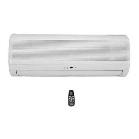
WAP Series
Indoor Units
ODU WAP 9 R22
ODU WAP 12 R22
ODU WAP 9 R410A EU
ODU WAP 12 R410A EU
ODU WAPI 9 R410A RC
ODU WAPI 9 R410A A2 RC
ODU WAPI 12 R410A RC
ODU WAPI 12 R410A A2 RC
R22
AUGUST – 2008
CONTENT
Outdoor Units
COOLING ONLY
HEAT PUMP
Advertisement


Need help?
Do you have a question about the WAP Series and is the answer not in the manual?
Questions and answers