Table of Contents
Advertisement
EFL-3R410
3-WAY FLOW LOGIC
O U T D O O R
U N I T S
E FL 80-3R410
E FL 100-3R410
E FL 120-3R410
E FL 140-3R410
E FL 160-3R410
Technical Manual
TM-EFL-A-1-AN
Cancels and Replaces:
A P P L I C A B L E
I N D O O R U N I T S
NK FL , NW FL , NK 2FL ,
NDL P , NFFL , DNHP ,
NK S FL , NP FL
3 i-410
V /Ø/H z
O U T D O O R
380-415/3Ø/50
INDOOR
220-240/1Ø/50
D R V
R A N G E
Advertisement
Chapters
Table of Contents

Related Manuals for Airwell EFL 80-3R410


Summary of Contents for Airwell EFL 80-3R410
- Page 1 EFL-3R410 3 i-410 3-WAY FLOW LOGIC O U T D O O R A P P L I C A B L E V /Ø/H z U N I T S I N D O O R U N I T S E FL 80-3R410 O U T D O O R E FL 100-3R410...
- Page 2 04-218 Airwell-cover-contents.qxp 01/06/2007 13:20 Page i IMPORTANT! Please Read Before Starting When Installing… …In a Room This air conditioning system meets strict safety and operating standards. As the installer or service person, it is an impor- Properly insulate any tubing run inside a room to prevent tant part of your job to install or service the system so it oper- “sweating”...
- Page 3 04-218 Airwell-cover-contents.qxp 01/06/2007 13:20 Page ii Check of Density Limit 2. The standards for minimum room volume are as follows. The room in which the air conditioner is to be installed requires a design that in the event of (1) No partition (shaded portion) refrigerant gas leaking out, its density will not exceed a set limit.
-
Page 4: Table Of Contents
04-218 Airwell-cover-contents.qxp 01/06/2007 13:20 Page iii CONTENTS Section 1. OUTLINE OF 3-WAY FLOW LOGIC ....... . .1-1 1. -
Page 5: Outline Of 3-Way Flow Logic
04-218 Airwell-1.qxp 01/06/2007 13:16 Page 1 Outline of 3-WAY FLOW LOGIC Contents 1. OUTLINE OF 3-WAY FLOW LOGIC 1. Line-up ............. . . 1-2 2. -
Page 6: Line-Up
04-218 Airwell-1.qxp 01/06/2007 13:16 Page 2 Outline of 3-WAY FLOW LOGIC 1. Line-up Indoor units Type Capacity: kW 2.2 (7,500) 2.8 (9,600) 3.6 (12,000) 5.6 (19,000) 7.3 (25,000) 10.6 (36,000) 14.0 (47,800) (BTU/h) Cooling 2.5 (8,500) 3.2 (11,000) 4.2 (14,000) 6.3 (21,000) -
Page 7: Line-Up
Cooling / Heating / 31.5 (107,500) / 37.5 (128,000) Air direction Outdoor Unit Space for creating on-site holes (Maximum hole size φ48) EFL100-3R410 EFL 80-3R410 EFL 120-3R410 DC inverter unit Type Capacity: kW (BTU/h) 40.0 (136,400) 45.0 (153,00) Cooling / Heating / 45.0 (153,500) -
Page 8: Features Of 3-Way Flow Logic
04-218 Airwell-1.qxp 01/06/2007 13:16 Page 4 Outline of 3-WAY FLOW LOGIC 2. Features of 3-WAY FLOW LOGIC 2-1. Outline of 3-WAY FLOW LOGIC ■ ■ System example Inverter unit Inverter unit Since all tubings are CONCENTRATION concentrated into one pipe shaft, you... - Page 9 04-218 Airwell-1.qxp 01/06/2007 13:16 Page 5 Outline of 3-WAY FLOW LOGIC 2. Features of 3-WAY FLOW LOGIC ■ ■ Dimensions 8, 10, 12, 14, 16 HP Air direction EFL 80R-3R410 10HP EFL 100R-3R410 12HP EFL 120R-3R410 Air direction 14HP EFL 140R-3R410...
- Page 10 04-218 Airwell-1.qxp 01/06/2007 13:16 Page 6 Outline of 3-WAY FLOW LOGIC 2. Features of 3-WAY FLOW LOGIC ■ ■ Capacity control The compressor combination (DC inverter compressor + constant-speed compressor) allows smooth capacity con- trol from 0.8 HP to 48 HP.
-
Page 11: Design Of 3-Way Flow Logic
04-218 Airwell-2.qxp 01/06/2007 13:15 Page 1 Design of 3-WAY FLOW LOGIC Contents 2. DESIGN OF 3-WAY FLOW LOGIC 1. Model Selecting and Capacity Calculator ........2-2 2. -
Page 12: Model Selecting And Capacity Calculator
04-218 Airwell-2.qxp 01/06/2007 13:15 Page 2 Design of 3-WAY FLOW LOGIC 1. Model Selecting and Capacity Calculator 1-1. Operating Range Heating and Cooling Operating range –5 –10 –15 –20 Indoor air intake temp. °C (DB) Heating Cooling Operating Operating range range –5... -
Page 13: Outdoor Unit
04-218 Airwell-2.qxp 01/06/2007 13:15 Page 3 Design of 3-WAY FLOW LOGIC 1. Model Selecting and Capacity Calculator 1-2. Procedure for Selecting Models and Calculating Capacity ■ ■ Model Selection Procedure Select the model and calculate the capacity for each refrigerant system according to the procedure shown below. - Page 14 04-218 Airwell-2.qxp 01/06/2007 13:15 Page 4 Design of 3-WAY FLOW LOGIC 1. Model Selecting and Capacity Calculator 1-3. Design of Tubing Length Select the installation location so that the length and size of refrigerant tubing are within the allowable range shown in the figure below.
-
Page 15: Type
(For the portion that exceeds 50 m, set based on the main tube sizes (LA) listed in the table on the following page.) Refrigerant Charge Amount at Shipment (for outdoor unit) EFL 80-3R410 EFL 100-3R410 EFL 120-3R410 (kg) 12.0... - Page 16 04-218 Airwell-2.qxp 01/06/2007 13:15 Page 6 Design of 3-WAY FLOW LOGIC 1. Model Selecting and Capacity Calculator ■ ■ Tubing size Main Tubing Size (LA) Unit: mm 22.4 28.0 33.5 40.0 45.0 50.4 56.0 61.5 68.0 73.0 78.5 85.0 90.0 96.0...
-
Page 17: Indoor Unit
04-218 Airwell-2.qxp 01/06/2007 13:15 Page 7 Design of 3-WAY FLOW LOGIC 1. Model Selecting and Capacity Calculator ■ Amount of Refrigerant Charge Narrow tubing size Amount of refrigerant charge/m (g/m) φ 6.35 φ 9.52 φ 12.7 φ 15.88 φ 19.05 φ... -
Page 18: Installation Standards
04-218 Airwell-2.qxp 01/06/2007 13:15 Page 8 Design of 3-WAY FLOW LOGIC ■ Installation standards Relationship between A/C units and the refrigerant tubing 4-tube layout 3-tube layout Solenoid 2-tube layout Outdoor unit Outdoor unit Indoor unit valve kit Suction tube Suction tube... - Page 19 04-218 Airwell-2.qxp 01/06/2007 13:15 Page 9 Design of 3-WAY FLOW LOGIC 1. Model Selecting and Capacity Calculator ■ ■ Straight equivalent length of joints 1-6. Straight Equivalent Length of Joints Design the tubing system by referring to the following table for the straight equivalent length of joints.
- Page 20 04-218 Airwell-2.qxp 01/06/2007 13:15 Page 10 Design of 3-WAY FLOW LOGIC 1. Model Selecting and Capacity Calculator ■ ■ Additional refrigerant charge amount Additional refrigerant charge amount is calculated from the liquid tubing total length as follows. Amount of Refrigerant Charge Per Meter, According to Liquid Tubing Size...
- Page 21 04-218 Airwell-2.qxp 01/06/2007 13:15 Page 11 Design of 3-WAY FLOW LOGIC 1. Model Selecting and Capacity Calculator 1-5. Calculation of Actual Capacity of Indoor Unit ■ ■ Calculating the actual capacity of each indoor unit Because the capacity of a multi air-conditioner changes according to the temperature conditions, tubing length, elevation difference and other factors, select the correct model after taking into account the various correction val- ues.
- Page 22 04-218 Airwell-2.qxp 01/06/2007 13:15 Page 12 Design of 3-WAY FLOW LOGIC 1. Model Selecting and Capacity Calculator <Heating> Outdoor unit corrected heating capacity (5) = Outdoor unit rated heating capacity × Correction coefficient for ● model ((1) Page 2-13) × Correction coefficient for outdoor temper- ature conditions ((2) Page 2-13) ×...
- Page 23 04-218 Airwell-2.qxp 01/06/2007 13:15 Page 13 Design of 3-WAY FLOW LOGIC 1. Model Selecting and Capacity Calculator Refer to the graph below for the correction coefficients for Ruc and Ruh. Indoor unit capacity correction coefficient for Ruc (cooling) Indoor unit capacity correction coefficient for Ruh (heating) 0.8 0.9...
- Page 24 04-218 Airwell-2.qxp 01/06/2007 13:16 Page 14 Design of 3-WAY FLOW LOGIC 1. Model Selecting and Capacity Calculator ■ ■ Graph of indoor unit capacity characteristics (2 – (2)) Indoor unit cooling capacity characteristics Indoor unit heating capacity characteristics indicates the rating point.
- Page 25 04-218 Airwell-2.qxp 01/06/2007 13:16 Page 15 Design of 3-WAY FLOW LOGIC 1. Model Selecting and Capacity Calculator 1-6. Capacity Correction Graph According to Temperature Condition ■ ■ Capacity characteristics (The corrected capacity for specific temperature conditions can be found from the graphs below.) <Heating>...
- Page 26 04-218 Airwell-2.qxp 01/06/2007 13:16 Page 16 Design of 3-WAY FLOW LOGIC 1. Model Selecting and Capacity Calculator ● ● Inverter model rated performance values <50Hz models> Cooling Heating Item Cooling Power Heating Power capacity consumption capacity consumption Model (kW) (kW)
- Page 27 04-218 Airwell-2.qxp 01/06/2007 13:16 Page 17 Design of 3-WAY FLOW LOGIC 1. Model Selecting and Capacity Calculator ■ If the maximum tubing length (L1) exceeds 90 m (equivalent length), increase the tubing size of the main liquid, suction and discharge tubes (LM) by one rank.
-
Page 28: System Design
13:16 Page 18 Design of 3-WAY FLOW LOGIC 2. System Design 2-1. System Example (1) Below are the tables created using the “Airwell PAC/GHP System Diagram Software.” Details of the calculations are shown in (2). Outdoor Outdoor unit 1 unit 2... - Page 29 04-218 Airwell-2.qxp 01/06/2007 13:16 Page 19 Design of 3-WAY FLOW LOGIC 2. System Design Indoor unit changes The indoor unit in room 4, where the corrected indoor unit capacity is less than the maximum load, is increased by one rank.
- Page 30 Inverter unit Outdoor units 10HP: EFL 100-3R410 10HP: EFL 100-3R410 Type 224 Type 280 Type 280 Type 280 Extension 8HP: EFL 80-3R410 indoor units Elevation difference H = 4 m Extension outdoor units Elevation difference Type 112 Type 90...
- Page 31 04-218 Airwell-2.qxp 01/06/2007 13:16 Page 21 Design of 3-WAY FLOW LOGIC 2. System Design Additional refrigerant charge before extension Additional refrigerant Tubing length (m) Liquid tube (A) × (B) kg charge per 1 m (kg/m) (B) diameter φ9.52 0.056 0.112 φ9.52...
- Page 32 04-218 Airwell-2.qxp 01/06/2007 13:16 Page 22 Design of 3-WAY FLOW LOGIC 2. System Design ■ ■ Checking of limit density The limit density judgment is made based on the room with the indoor unit having the smallest capacity in the system after extension.
- Page 33 (If only 1 unit is connected, a ball (BV: purchased valve is also needed on this side.) separately) (Consult with AIRWELL separately concerning the Indoor unit (1) ball valve.) If a trap or ball valve is not added, do not oper-...
-
Page 34: Electrical Wiring
Time delay fuse or Time delay fuse or circuit capacity circuit capacity Wire size Max. length Wire size Max. length 6 mm 92 m EFL 80-3R410 6 mm 92 m 30 A 6 mm 70 m EFL 100-3R410 6 mm... - Page 35 04-218 Airwell-2.qxp 01/06/2007 13:16 Page 25 Design of 3-WAY FLOW LOGIC 3. Electrical Wiring 3-3. Wiring System Diagrams Indoor unit (No. 1) Power supply Outdoor unit 220-240V 50Hz INV unit Ground Power supply 380-415V-3N 50Hz Remote controller Ground Ground Ground...
- Page 36 04-218 Airwell-2.qxp 01/06/2007 13:16 Page 26 Design of 3-WAY FLOW LOGIC 3. Electrical Wiring (1) When linking outdoor units in a network (S-net link system), disconnect the terminal extended from the short plug (CN003, 2P Black, location: right bottom on the outdoor main control PCB) from all outdoor units except any one of the outdoor units.
- Page 37 04-218 Airwell-2.qxp 01/06/2007 13:16 Page 27 Design of 3-WAY FLOW LOGIC 3. Electrical Wiring (5) Use shielded wires for inter-unit control wiring (c) and ground the shield on both sides, other- wise misoperation from noise may occur. Shielded wire Connect wiring as shown in Section 3-3.
-
Page 38: Control Of 3-Way Flow Logic
04-218 Airwell-3_1-38.qxp 01/06/2007 13:14 Page 1 Control of 3-WAY FLOW LOGIC Contents 3. CONTROL OF 3 WAY FLOW LOGIC 1. Main Operating Functions ..........3-2 2. -
Page 39: Main Operating Functions
04-218 Airwell-3_1-38.qxp 01/06/2007 13:14 Page 2 Control of 3-WAY FLOW LOGIC 1. Main Operating Functions 1-1. Room Temperature Control The thermostat is turned ON/OFF according to ▲T as shown below. ▲T = Room temperature - Set temperature When remote controller... - Page 40 04-218 Airwell-3_1-38.qxp 01/06/2007 13:14 Page 3 Control of 3-WAY FLOW LOGIC 1. Main Operating Functions 1-2. Automatic Control for Heating and Cooling Automatic Heating/Cooling Control (1) When operation starts, heating or cooling is selected according to the set temperature and the room tempera- ture.
-
Page 41: Wireless Remote Controller
04-218 Airwell-3_1-38.qxp 01/06/2007 13:14 Page 4 Control of 3-WAY FLOW LOGIC 2. Wireless Remote Controller Optional Controller (Remote Controller) Wireless Remote Controller / RCIRK-FL (for NKFL type) / RCIRKS-FL (for NK2FL, NKSFL types) / RCIRP-FL (for NPFL type) / RCIRC-FL (for NDLP, NDHP types). - Page 42 04-218 Airwell-3_1-38.qxp 01/06/2007 13:14 Page 5 Control of 3-WAY FLOW LOGIC 2. Wireless Remote Controller F: FILTER button If a separately installed signal receiver is being employed, this button is used to turn off its filter lamp. When the filt er lamp has lighted, first clean the filter, and then press the FILTER button to turn off the filter lamp.
- Page 43 04-218 Airwell-3_1-38.qxp 01/06/2007 13:14 Page 6 Control of 3-WAY FLOW LOGIC 2. Wireless Remote Controller Indicator when swing operation is stopped Fan and heating Cooling and drying During cooling and drying, the flap does not stop at the downward position.
- Page 44 04-218 Airwell-3_1-38.qxp 01/06/2007 13:14 Page 7 Control of 3-WAY FLOW LOGIC 2. Wireless Remote Controller ■ Receiver The signal receivers with the exception of the separately installed signal receiver are mounted on the indoor units. NKFLD type NPFL type Separately installed...
- Page 45 04-218 Airwell-3_1-38.qxp 01/06/2007 13:14 Page 8 Control of 3-WAY FLOW LOGIC 2. Wireless Remote Controller How to Install the Wireless Remote Controller Receiver Indoor unit Indoor unit drain tube side refrigerant tube side ■ ■ RCIRK-FL for 4-Way Cassette (NKFL Type) Receiver unit 2-1.
- Page 46 04-218 Airwell-3_1-38.qxp 01/06/2007 13:14 Page 9 Control of 3-WAY FLOW LOGIC 2. Wireless Remote Controller 2-2. Accessories Q'ty Parts Q'ty Parts AAA alkaline battery Receiver Tapping screw unit 4 × 16 Clamp Remote Fastening screw control unit 4 × 12...
-
Page 47: Section 5. Test Run
04-218 Airwell-3_1-38.qxp 01/06/2007 13:14 Page 10 Control of 3-WAY FLOW LOGIC 2. Wireless Remote Controller (1) To assign the wired remote controller as the sub unit, locate the address connector at the rear of the wired remote controller PCB and disconnect it. Reconnect it to the sub unit position. - Page 48 04-218 Airwell-3_1-38.qxp 01/06/2007 13:14 Page 11 Control of 3-WAY FLOW LOGIC 2. Wireless Remote Controller ■ ■ RCIRP-FL for Ceiling Mounted Side panel (NPFL Type) Panel 2-6. Installing the Receiver Unit (1) To take off the side panel, open the intake grille and remove the screw.
- Page 49 04-218 Airwell-3_1-38.qxp 01/06/2007 13:14 Page 12 Control of 3-WAY FLOW LOGIC 2. Wireless Remote Controller 2-7. Accessories Supplied with Unit Q'ty Parts Q'ty AAA alkaline battery Receiver unit Tapping screw Remote control 4 × 16 unit Remote control holder 2-8. Wiring the Receiver Unit ●...
-
Page 50: Wired Remote Controller
04-218 Airwell-3_1-38.qxp 01/06/2007 13:14 Page 13 Control of 3-WAY FLOW LOGIC 2. Wireless Remote Controller When 1 indoor unit is operated with 2 remote controllers: (The indoor unit runs according to which of the remote controllers is assigned as the main or sub unit.) - Page 51 04-218 Airwell-3_1-38.qxp 01/06/2007 13:14 Page 14 Control of 3-WAY FLOW LOGIC 2. Wireless Remote Controller ■ ■ RCIRKS-FL for 2-Way and High Ceiling Cover A Cover B 1-Way Type (NK2FL, NKSL Type) Display For 2-way Cassette Type (NK2FL Type) 2-11. Installing the Display Spread ●...
- Page 52 04-218 Airwell-3_1-38.qxp 01/06/2007 13:14 Page 15 Control of 3-WAY FLOW LOGIC 2. Wireless Remote Controller For 1-Way Air Discharge High-Ceiling Cassette Type (NKSFL Type) 2-13. Installing the Display ● Remove the side panel and ceiling panel. Install the display. Ceiling panel hole (1) Remove the side panel.
- Page 53 04-218 Airwell-3_1-38.qxp 01/06/2007 13:14 Page 16 Control of 3-WAY FLOW LOGIC 2. Wireless Remote Controller (4) Attach the ceiling panel. Service cover Control unit (5) Open the air-intake grille. Connect the display and the control unit 6P relay connector (white).
- Page 54 04-218 Airwell-3_1-38.qxp 01/06/2007 13:14 Page 17 Control of 3-WAY FLOW LOGIC 2. Wireless Remote Controller ● The wireless receiver unit compo- nents cannot be used for more than CAUTION 1 indoor unit at a time. (However, separate receiver units may be used simultaneously.) ●...
- Page 55 04-218 Airwell-3_1-38.qxp 01/06/2007 13:14 Page 18 Control of 3-WAY FLOW LOGIC 2. Wireless Remote Controller 2-18. How to Use the Test Run Setting 1. Set DIP switch [DS] No. 1 on the wireless receiver DS switch “1” unit PCB from OFF to the ON position.
- Page 56 04-218 Airwell-3_1-38.qxp 01/06/2007 13:14 Page 19 Control of 3-WAY FLOW LOGIC 2. Wireless Remote Controller ■ ■ RCIRC-FL for NDLP, NDHP Type 2-19. Accessories Supplied with Separate Receiver Unit Q'ty Parts Q'ty Parts Separate Spacer receiver unit (provided 200mm Wire joints...
- Page 57 04-218 Airwell-3_1-38.qxp 01/06/2007 13:14 Page 20 Control of 3-WAY FLOW LOGIC 2. Wireless Remote Controller ● For flush mounting into a wall, install the separate Face plate receiver unit in a metal switch box (field supply) that has been recessed into the wall in advance.
- Page 58 04-218 Airwell-3_1-38.qxp 01/06/2007 13:14 Page 21 Control of 3-WAY FLOW LOGIC 2. Wireless Remote Controller 1. Insert a screwdriver or similar tool into the notch at the bottom to remove the receiver nameplate. 2. Cut a section out of the ceiling along the provided paper pattern (95 ×...
- Page 59 04-218 Airwell-3_1-38.qxp 01/06/2007 13:14 Page 22 Control of 3-WAY FLOW LOGIC 2. Wireless Remote Controller 2-22. Wiring the Separate Receiver Unit * Use wires that are 0.5 mm – 2 mm in diameter. * The wiring length must not exceed 400 m.
- Page 60 04-218 Airwell-3_1-38.qxp 01/06/2007 13:14 Page 23 Control of 3-WAY FLOW LOGIC 2. Wireless Remote Controller 2-23. Important Information for Installation of 2 Separate Receiver Units When using 2 receiver units to operate 1 or more indoor units at the same time, follow the procedure below to install them.
- Page 61 04-218 Airwell-3_1-38.qxp 01/06/2007 13:14 Page 24 Control of 3-WAY FLOW LOGIC 2. Wireless Remote Controller 2-24. Test Run Setting 1. Remove the receiver unit face plate, and set the DIP switch to “Test Run - ON” position. 2. Run the air conditioner using the wireless remote controller by pressing the “ON/OFF”...
-
Page 62: Wired Remote Controller / Nrcg-Fl
04-218 Airwell-3_1-38.qxp 01/06/2007 13:14 Page 25 Control of 3-WAY FLOW LOGIC 3. Wired Remote Controller / NRCG-FL Wired Remote Controller / NRCG-FL ■ ■ How to Use the Wired Remote Controller This remote control unit can be used to operate up to 8 indoor units. -
Page 63: Wired Remote Control / Nrcg-Fl
04-218 Airwell-3_1-38.qxp 01/06/2007 13:14 Page 26 Control of 3-WAY FLOW LOGIC 3. Wired Remote Controller / NRCG-FL F: FILTER button This button is used to turn off the filter sign ( ). When the filter sign appears on the display, clean the filter, and then press this button to turn off the sign. - Page 64 04-218 Airwell-3_1-38.qxp 01/06/2007 13:14 Page 27 Control of 3-WAY FLOW LOGIC 3. Wired Remote Controller / NRCG-FL J: TIMER SET button Use this button while the unit is operating to switch between timer settings. (OFF Timer) The air conditioner stops after a preset time elapses.
- Page 65 04-218 Airwell-3_1-38.qxp 01/06/2007 13:58 Page 28 Control of 3-WAY FLOW LOGIC 3. Wired Remote Controller / NRCG-FL ■ Display Description A: When the unit is in heating standby status, the indicator appears. While this indicator is displayed, the indoor fan turns off or on at low fan speed.
- Page 66 04-218 Airwell-3_1-38.qxp 01/06/2007 13:14 Page 29 Control of 3-WAY FLOW LOGIC 3. Wired Remote Controller / NRCG-FL ■ Setting the Timer Using the timer Set the timer during air conditioner operation. Recommended usage Display To stop the air conditioner after a preset time...
- Page 67 04-218 Airwell-3_1-38.qxp 01/06/2007 13:14 Page 30 Control of 3-WAY FLOW LOGIC 3. Wired Remote Controller / NRCG-FL How to set the OFF timer ( Example: Stopping the air conditioner after 3.5 hours of operation Operation Indication 1. Press the ON/OFF button once to start the air conditioner.
- Page 68 04-218 Airwell-3_1-38.qxp 01/06/2007 13:14 Page 31 Control of 3-WAY FLOW LOGIC 3. Wired Remote Controller / NRCG-FL ■ ■ How to Install the Remote Controller Do not supply power to the unit or try to operate it until CAUTION Remote controller wiring can be extended to a maxi- the tubing and wiring to the mum of 1,000 m.
- Page 69 04-218 Airwell-3_1-38.qxp 01/06/2007 13:14 Page 32 Control of 3-WAY FLOW LOGIC 3. Wired Remote Controller / NRCG-FL ■ ■ Basic Wiring Diagram Install wiring correctly Remote CAUTION control wiring (incorrect wiring will dam- age the equipment). Standard Multiple Group control...
- Page 70 04-218 Airwell-3_1-38.qxp 01/06/2007 13:14 Page 33 Control of 3-WAY FLOW LOGIC 3. Wired Remote Controller / NRCG-FL Setting the main and sub remote controllers 1. Set one of the 2 connected remote controllers as the main remote controller. 2. On the other remote controller (sub-remote controller), switch the remote controller address connector on the rear of the remote controller PCB from Main to Sub.
- Page 71 04-218 Airwell-3_1-38.qxp 01/06/2007 13:15 Page 34 Control of 3-WAY FLOW LOGIC 3. Wired Remote Controller / NRCG-FL ■ ■ Switching the Room Temperature Sensors Room temperature sensors are contained in the indoor unit and in the remote controller. One or the other of the temperature sensors is used for operation. Normally, the indoor unit sensor is set; however, the procedure below can be used to switch to the remote controller sensor.
- Page 72 04-218 Airwell-3_1-38.qxp 01/06/2007 13:15 Page 35 Control of 3-WAY FLOW LOGIC 3. Wired Remote Controller / NRCG-FL ■ ■ Wiring the Remote Controller <Flush Mounting> ● Connection diagram Approx. 200 mm Remote Terminal board for controller indoor unit remote unit...
- Page 73 04-218 Airwell-3_1-38.qxp 01/06/2007 13:15 Page 36 Control of 3-WAY FLOW LOGIC 3. Wired Remote Controller / NRCG-FL ■ ■ Meaning of Alarm Messages Table of Self-Diagnostics Functions and Description of Alarm Displays Alarm messages are indicated by the blinking of LED 1 and 2 (D72, D75) on the outdoor unit PCB. They are also displayed on the wired remote controller.
- Page 74 04-218 Airwell-3_1-38.qxp 01/06/2007 13:15 Page 37 Control of 3-WAY FLOW LOGIC 3. Wired Remote Controller / NRCG-FL Alarm Possible cause of malfunction message Activation of Protective device in outdoor unit Compressor thermal protector is activated. Power supply voltage is unusual. (The voltage is more than 260 V protective is activated.
- Page 75 04-218 Airwell-3_1-38.qxp 01/06/2007 13:15 Page 38 Control of 3-WAY FLOW LOGIC 3. Wired Remote Controller / NRCG-FL Alarm messages displayed on system controller Serial Error in transmitting serial Indoor or main outdoor unit is not operating correctly. communication signal Mis-wiring of control wiring between indoor unit, main outdoor unit communication and system controller.
-
Page 76: System Controller / Nrsc-Fl
04-218 Airwell-3_p39-60.qxp 01/06/2007 13:13 Page 39 Control of 3-WAY FLOW LOGIC 4. System Controller / NRSC-FL System Controller / NRSC-FL ■ ■ Operation Buttons A: ALL/ZONE/GR B: ZONE select C: GROUP select SELECT button button buttons F: Operation lamp D: ON button... - Page 77 04-218 Airwell-3_p39-60.qxp 01/06/2007 13:13 Page 40 Control of 3-WAY FLOW LOGIC 4. System Controller / NRSC-FL D: ON button This button is for turning the selected air conditioner on. E: OFF button This button is for turning the selected air conditioner off.
- Page 78 04-218 Airwell-3_p39-60.qxp 01/06/2007 13:13 Page 41 Control of 3-WAY FLOW LOGIC 4. System Controller / NRSC-FL K: CHECK button This button is used only when servicing the air conditioner. Do not use the CHECK button for normal operation. CAUTION L: CENTRAL...
- Page 79 04-218 Airwell-3_p39-60.qxp 01/06/2007 13:13 Page 42 Control of 3-WAY FLOW LOGIC 4. System Controller / NRSC-FL ■ Display Description When the unit is in heating standby status, the indicator appears. The currently selected operation mode is displayed. The currently selected FAN SPEED, Airflow Direction and SWEEP settings are displayed.
- Page 80 04-218 Airwell-3_p39-60.qxp 01/06/2007 13:13 Page 43 Control of 3-WAY FLOW LOGIC 4. System Controller / NRSC-FL ■ How to Start Group Operation To start group operation Stop Power Turn the power supply switch on more than 5 hours before starting operation.
- Page 81 04-218 Airwell-3_p39-60.qxp 01/06/2007 13:13 Page 44 Control of 3-WAY FLOW LOGIC 4. System Controller / NRSC-FL ■ How to Start Collective Operation To start collective operation (ALL or ZONE) Stop Power Turn the power supply switch on 5 hours or more before starting operation.
- Page 82 04-218 Airwell-3_p39-60.qxp 01/06/2007 13:13 Page 45 Control of 3-WAY FLOW LOGIC 4. System Controller / NRSC-FL ■ How to Install the System Controller Installation site selection Install the system controller at a height of between 1 and 1.5 meters above the floor.
- Page 83 04-218 Airwell-3_p39-60.qxp 01/06/2007 13:13 Page 46 Control of 3-WAY FLOW LOGIC 4. System Controller / NRSC-FL ■ Overview of the System Controller Electrical component box Hole for electrical Control unit Unit: mm wiring Mounting plate (for flush mounting) φ 5 diameter holes...
- Page 84 04-218 Airwell-3_p39-60.qxp 01/06/2007 13:13 Page 47 Control of 3-WAY FLOW LOGIC 4. System Controller / NRSC-FL ■ Installation Procedure Mounting plate Electrical component box Hole for electrical wiring a): Normal mounting Rear plate Fig. 2 Fig. 3-30 b): Flush mounting 1.
- Page 85 04-218 Airwell-3_p39-60.qxp 01/06/2007 13:13 Page 48 Control of 3-WAY FLOW LOGIC 4. System Controller / NRSC-FL ■ Layout of Electrical Terminals Clamp for electrical wiring Connector (CN02) for weekly timer or schedule timer (optional) CN02 Ground for power wiring B3 B2 B1 A3 A2 A1...
- Page 86 04-218 Airwell-3_p39-60.qxp 01/06/2007 13:13 Page 49 Control of 3-WAY FLOW LOGIC 4. System Controller / NRSC-FL ■ Basic Wiring Diagram Ensure that wiring connections are correct. (Incorrect wiring will CAUTION damage the equipment.) Outdoor Outdoor Outdoor Outdoor ≤ unit 1...
- Page 87 04-218 Airwell-3_p39-60.qxp 01/06/2007 13:13 Page 50 Control of 3-WAY FLOW LOGIC 4. System Controller / NRSC-FL ■ Address Switch Setting To avoid an electric shock hazard, To Installers, DO NOT touch any terminal on the WA R N I N G...
- Page 88 04-218 Airwell-3_p39-60.qxp 01/06/2007 13:13 Page 51 Control of 3-WAY FLOW LOGIC 4. System Controller / NRSC-FL Main/sub selection switch 2 3 4 5 6 7 8 OFF: System controller operates as main controller. ON: System controller operates as sub-controller. ALL/ZONE mode selection switch...
- Page 89 04-218 Airwell-3_p39-60.qxp 01/06/2007 13:13 Page 52 Control of 3-WAY FLOW LOGIC 4. System Controller / NRSC-FL Weekly timer input switches. 2 3 4 5 6 7 8 System controller operation can be set when weekly timer activates (ON/OFF). Switch No.
- Page 90 04-218 Airwell-3_p39-60.qxp 01/06/2007 13:13 Page 53 Control of 3-WAY FLOW LOGIC 4. System Controller / NRSC-FL ■ Mode Setting According to function of each system controller, set Central control Remote control SW1 as Fig. 3-35. mode mode (1) Central control/Remote control mode...
- Page 91 04-218 Airwell-3_p39-60.qxp 01/06/2007 13:13 Page 54 Control of 3-WAY FLOW LOGIC 4. System Controller / NRSC-FL ■ How to Perform Zone Registration To operate the system controller properly, zone registration is required after finishing the test run (and after setting all indoor unit addresses) using one of the following methods.
- Page 92 04-218 Airwell-3_p39-60.qxp 01/06/2007 13:13 Page 55 Control of 3-WAY FLOW LOGIC 4. System Controller / NRSC-FL ■ Zone Registration Table Indoor unit Indoor unit Central Unit Central Unit address ZONE GROUP address ZONE GROUP address location address location (UNIT No.) (UNIT No.)
- Page 93 04-218 Airwell-3_p39-60.qxp 01/06/2007 13:13 Page 56 Control of 3-WAY FLOW LOGIC 4. System Controller / NRSC-FL (a) Zone registration using the remote controller (NRCG-FL) (Determination of central address) In this case, after confirming which indoor unit is connected to the remote controller and that the air conditioner in the OFF state, you set the central addresses one at a time.
- Page 94 04-218 Airwell-3_p39-60.qxp 01/06/2007 13:13 Page 57 Control of 3-WAY FLOW LOGIC 4. System Controller / NRSC-FL (b) Zone registration using the system controller (NRSC-FL) ✟ In this case, you set all Central addresses by system If no data is controller at once manually.
- Page 95 04-218 Airwell-3_p39-60.qxp 01/06/2007 13:13 Page 58 Control of 3-WAY FLOW LOGIC 4. System Controller / NRSC-FL ■ How to Check Overlapping of Central Address Nos. (1) Press the buttons at the same time for more than 4 seconds. and CODE No. C1 will flash.
- Page 96 04-218 Airwell-3_p39-60.qxp 01/06/2007 13:13 Page 59 Control of 3-WAY FLOW LOGIC 4. System Controller / NRSC-FL ■ System Examples The following diagrams show system examples and the correct setting of the switches on the PCB. (1) For a system without link...
- Page 97 04-218 Airwell-3_p39-60.qxp 01/06/2007 13:13 Page 60 Control of 3-WAY FLOW LOGIC 4. System Controller / NRSC-FL (2) For a system with link 3 - 60...
-
Page 98: Schedule Timer / Nwtm-Fl
04-218 Airwell-3_p61-85.qxp 01/06/2007 13:12 Page 61 Control of 3-WAY FLOW LOGIC 5. Schedule Timer / NWTM-FL Schedule Timer / NWTM-FL ■ ■ Operation Buttons A: PROGRAM button E: HOLIDAY button B: PROG. COPY buttons F: CANCEL button C: CLEAR button... - Page 99 04-218 Airwell-3_p61-85.qxp 01/06/2007 13:12 Page 62 Control of 3-WAY FLOW LOGIC 5. Schedule Timer / NWTM-FL ■ ■ Display A: Today’s day of the week Indicates today’ s day of the week. B: Program schedule Appears under days that are scheduled for program operation.
- Page 100 04-218 Airwell-3_p61-85.qxp 01/06/2007 13:12 Page 63 Control of 3-WAY FLOW LOGIC 5. Schedule Timer / NWTM-FL ■ ■ Setting the Present Time Set the present time. (Example: When the present time is 12:45) STEP 1 Hold down the SET button and press the HH button to set the hour.
- Page 101 04-218 Airwell-3_p61-85.qxp 01/06/2007 13:12 Page 64 Control of 3-WAY FLOW LOGIC 5. Schedule Timer / NWTM-FL ■ ■ Setting Today’s Day of the Week Set today’s day of the week. (Example: When today is Wednesday) STEP 1 Hold down the SET button and press the DAY button to set today’s day of the week.
- Page 102 04-218 Airwell-3_p61-85.qxp 01/06/2007 13:12 Page 65 Control of 3-WAY FLOW LOGIC 5. Schedule Timer / NWTM-FL ■ ■ Setting Up Programmed Operations Example settings Correctly set the present time and today’s day of the week. Unless both are correctly set, the programs will not run as expected.
- Page 103 04-218 Airwell-3_p61-85.qxp 01/06/2007 13:12 Page 66 Control of 3-WAY FLOW LOGIC 5. Schedule Timer / NWTM-FL STEP 3 Set up the program and press the SET button. • Select timer operation with the (timer ON/ OFF) button and (remote controller operation enable/disable) button.
- Page 104 04-218 Airwell-3_p61-85.qxp 01/06/2007 13:12 Page 67 Control of 3-WAY FLOW LOGIC 5. Schedule Timer / NWTM-FL ■ ■ Setting Errors If time is set as shown below while setting up a program, “ERROR” is displayed (the indication blinks). Therefore, correct the time setting.
- Page 105 04-218 Airwell-3_p61-85.qxp 01/06/2007 13:12 Page 68 Control of 3-WAY FLOW LOGIC 5. Schedule Timer / NWTM-FL ■ ■ How to Check Program Times You can check the programmed times for each group and day of the week. STEP 1 Press the GROUP button and select a group whose time you want to check.
- Page 106 04-218 Airwell-3_p61-85.qxp 01/06/2007 13:12 Page 69 Control of 3-WAY FLOW LOGIC 5. Schedule Timer / NWTM-FL ■ ■ How to Copy Program Times You can copy the already set program of one day into another day (Day Program Copying), as well as copy the entire week programmed for one group into another group (Group Program Copying).
- Page 107 04-218 Airwell-3_p61-85.qxp 01/06/2007 13:12 Page 70 Control of 3-WAY FLOW LOGIC 5. Schedule Timer / NWTM-FL STEP 4 Press the SET button to copy. • Press the SET button and the program schedule marker ( ) will be displayed. STEP 5 Select other copy destination days if desired.
- Page 108 04-218 Airwell-3_p61-85.qxp 01/06/2007 13:12 Page 71 Control of 3-WAY FLOW LOGIC 5. Schedule Timer / NWTM-FL ■ ■ How to Copy Group Programs STEP 1 Press the PROG. COPY GROUP button. • “CP-1” starts blinking in the present time display area and “CP”...
- Page 109 04-218 Airwell-3_p61-85.qxp 01/06/2007 13:12 Page 72 Control of 3-WAY FLOW LOGIC 5. Schedule Timer / NWTM-FL STEP 5 Select other copy destination groups if desired. • You can copy the selected source group programs into other groups by repeatedly pressing the GROUP button to select a group followed by the SET button to set it.
- Page 110 04-218 Airwell-3_p61-85.qxp 01/06/2007 13:12 Page 73 Control of 3-WAY FLOW LOGIC 5. Schedule Timer / NWTM-FL ■ ■ How to Set Holidays in a Scheduled Week of Operation Operations programmed for a specific day during the week can be temporarily disabled by setting that day as a holiday.
- Page 111 04-218 Airwell-3_p61-85.qxp 01/06/2007 13:12 Page 74 Control of 3-WAY FLOW LOGIC 5. Schedule Timer / NWTM-FL STEP 4 Press the HOLIDAY button to enter the holiday. • The normal display returns. To halt programmed operation for one week or more, you can disable all timer programs.
- Page 112 04-218 Airwell-3_p61-85.qxp 01/06/2007 13:12 Page 75 Control of 3-WAY FLOW LOGIC 5. Schedule Timer / NWTM-FL ■ ■ How to Clear Programs Press the PROGRAM button. • When the PROGRAM button is pressed, the group No. and the present day of the week start blinking and the present time indication changes to a blinking “PG-1”.
- Page 113 04-218 Airwell-3_p61-85.qxp 01/06/2007 13:12 Page 76 Control of 3-WAY FLOW LOGIC 5. Schedule Timer / NWTM-FL ■ ■ Schedule Timer and Air Conditioner Operation Air conditioners operate either according to operations programmed from the schedule timer (starting/stopping and remote control operation enable/disable) or according to a connected remote controller or system controller.
- Page 114 04-218 Airwell-3_p61-85.qxp 01/06/2007 13:12 Page 77 Control of 3-WAY FLOW LOGIC 5. Schedule Timer / NWTM-FL ■ ■ Power Outages If the air conditioner is running when power is lost, the air conditioner remains OFF when power is restored. Also, if remote controller operation was disabled when power was lost, it is enabled for a few minutes when power is restored.
- Page 115 04-218 Airwell-3_p61-85.qxp 01/06/2007 13:12 Page 78 Control of 3-WAY FLOW LOGIC 5. Schedule Timer / NWTM-FL ■ ■ Troubleshooting Before requesting servicing, check the following. Trouble Cause/Remedy blinks on the display. The schedule timer is performing initial communications with connected indoor units. Wait for communications to finish.
- Page 116 04-218 Airwell-3_p61-85.qxp 01/06/2007 13:12 Page 79 Control of 3-WAY FLOW LOGIC 5. Schedule Timer / NWTM-FL ■ ■ Accessories for Schedule Timer Supplied parts Supplied parts Q'ty Q'ty T10 power wire Spacers Wire joints (with current fuse) *1 T10 relay wire *2...
- Page 117 04-218 Airwell-3_p61-85.qxp 01/06/2007 13:13 Page 80 Control of 3-WAY FLOW LOGIC 5. Schedule Timer / NWTM-FL ■ ■ Installation of Connected Schedule Timers When installing schedule timers (remote controller switches, system controllers, etc.) onto the wall, use the method shown in Figs. 3-44 and 3-45.
- Page 118 04-218 Airwell-3_p61-85.qxp 01/06/2007 13:13 Page 81 Control of 3-WAY FLOW LOGIC 5. Schedule Timer / NWTM-FL ● Wiring The schedule timer wiring can be connected by the following two methods. Select one of these connection meth- ods according to the actual installation location.
-
Page 119: About The Setting Switches
04-218 Airwell-3_p61-85.qxp 01/06/2007 13:13 Page 82 Control of 3-WAY FLOW LOGIC 5. Schedule Timer / NWTM-FL ■ ■ About the Setting Switches Complete the switch settings before turning ON the schedule timer power. Remote Controller Enable Items (1) Connection (1) - Page 120 04-218 Airwell-3_p61-85.qxp 01/06/2007 13:13 Page 83 Control of 3-WAY FLOW LOGIC 5. Schedule Timer / NWTM-FL ■ ■ Creating Timer Groups [Setting fixed timer groups] The schedule timer can be set for 6 time status 1 fixed timer group (64 units together) changes.
- Page 121 04-218 Airwell-3_p61-85.qxp 01/06/2007 13:13 Page 84 Control of 3-WAY FLOW LOGIC 5. Schedule Timer / NWTM-FL (4) To continue registering addresses, repeat step (3). (Central control address numbers will be added to the right side of the LCD display.) To cancel a registered central control address, use the...
- Page 122 04-218 Airwell-3_p61-85.qxp 01/06/2007 13:13 Page 85 Control of 3-WAY FLOW LOGIC 5. Schedule Timer / NWTM-FL ■ ■ Installation Work Plan Schedule timer Central Indoor unit control ● Use the wired remote controller to check the unit Fixed timer group Unit No.
-
Page 123: Simplified Remote Controller / Nrcb-Fl
04-218 Airwell-3_p86-96.qxp 01/06/2007 13:11 Page 86 Control of 3-WAY FLOW LOGIC 6. Simplified Remote Controller / NRCB-FL Simplified Remote Controller / NRCB-FL ■ ■ Operation Buttons C: Temperature setting buttons D: FAN SPEED selector button A: ON/OFF operation B: MODE button... - Page 124 04-218 Airwell-3_p86-96.qxp 01/06/2007 13:11 Page 87 Control of 3-WAY FLOW LOGIC 6. Simplified Remote Controller / NRCB-FL D: FAN SPEED selector button (AUTO) : The air conditioner automatically decides the fan speed. (HI) : High fan speed (MED) : Medium fan speed...
- Page 125 04-218 Airwell-3_p86-96.qxp 01/06/2007 13:11 Page 88 Control of 3-WAY FLOW LOGIC 6. Simplified Remote Controller / NRCB-FL ■ ■ Display Description A: This is displayed to indicate that the system controller is being used for control. When indicator is flashing on the display, the operation is not accepted by the system controller.
- Page 126 04-218 Airwell-3_p86-96.qxp 01/06/2007 13:11 Page 89 Control of 3-WAY FLOW LOGIC 6. Simplified Remote Controller / NRCB-FL ■ ■ Operation STEP 4 STEP 3 STEP 2 STEP 1 STEP 5 NOTE To warm up the system, the power mains must be turned on at least five (5) hours before operation.
- Page 127 04-218 Airwell-3_p86-96.qxp 01/06/2007 13:11 Page 90 Control of 3-WAY FLOW LOGIC 6. Simplified Remote Controller / NRCB-FL ■ ■ Troubleshooting If your air conditioner does not work properly, fir st check the following points before requesting service. If it still does not work properly, contact your dealer or a service center.
- Page 128 04-218 Airwell-3_p86-96.qxp 01/06/2007 13:11 Page 91 Control of 3-WAY FLOW LOGIC 6. Simplified Remote Controller / NRCB-FL ■ ■ Parts Supplied with Simplified Remote Controller Supplied parts Supplied parts Simplified remote Spacers controller (comes with 200 mm wire) Wire joints Machine screws M4 ×...
- Page 129 04-218 Airwell-3_p86-96.qxp 01/06/2007 13:11 Page 92 Control of 3-WAY FLOW LOGIC 6. Simplified Remote Controller / NRCB-FL 1. Insert a screwdriver or the like in the groove on the lower side of the simplified remote controller body to pry off the back case.
- Page 130 04-218 Airwell-3_p86-96.qxp 01/06/2007 13:11 Page 93 Control of 3-WAY FLOW LOGIC 6. Simplified Remote Controller / NRCB-FL ■ ■ Guidelines for Using 2 Simplified Remote Controllers This multiple remote controller system controls 1 to 8 indoor units with 2 simplified remote controllers.
-
Page 131: Remote Sensor / Nsd
04-218 Airwell-3_p86-96.qxp 01/06/2007 13:11 Page 94 Control of 3-WAY FLOW LOGIC 7. Remote Sensor / NSD Remote Sensor / NSD ■ ■ Parts Supplied with Remote Sensor Supplied parts Remote sensor (comes with 200 mm wire) Machine screws M4 × 25... - Page 132 04-218 Airwell-3_p86-96.qxp 01/06/2007 13:11 Page 95 Control of 3-WAY FLOW LOGIC 7. Remote Sensor / NSD ■ ■ How to Install the Remote Sensor < NOTE 1 > Do not twist the remote sensor wiring with the power wiring or run it in the same metal conduit, because this may cause malfunction.
- Page 133 04-218 Airwell-3_p86-96.qxp 01/06/2007 13:11 Page 96 Control of 3-WAY FLOW LOGIC 7. Remote Sensor / NSD ■ ■ How to Wire the Remote Sensor Connection diagram Terminal block Remote for wiring the sensor remote controller of the indoor unit Wiring from remote...
-
Page 134: 3-Way Flow Logic Unit Specifications
04-218 Airwell-4_1.qxp 01/06/2007 13:10 Page 1 3-WAY FLOW LOGIC Unit Specifications Contents 4. 3-WAY FLOW LOGIC UNIT SPECIFICATIONS 1. Outdoor Unit ............4-2 2. -
Page 135: Outdoor Unit
Unit Specifications (1) MODEL NAME 3-WAY FLOW LOGIC Capacity Control Outdoor Unit <8, 10 horsepower> MODEL No. EFL 80-3R410 EFL 100-3R410 380 - 400 - 415V / 3N / 50Hz 380 - 400 - 415V / 3N / 50Hz POWER SOURCE... - Page 136 04-218 Airwell-4_1.qxp 01/06/2007 13:10 Page 3 3-WAY FLOW LOGIC Unit Specifications 1. Outdoor Unit Unit Specifications (2) MODEL NAME 3-WAY FLOW LOGIC Capacity Control Outdoor Unit <12, 14, 16 horsepower> MODEL No. EFL 120-3R410 EFL 140-3R410 EFL 160-3R410 380 - 400 - 415V / 3N / 50Hz...
- Page 137 Unit Specifications (3) MODEL NAME 3-WAY FLOW LOGIC Capacity Control Outdoor Unit <18 horsepower> COMPONENT OUTDOOR UNIT EFL 100-3R410 EFL 80-3R410 380 - 400 - 415V / 3N / 50Hz 380 - 400 - 415V / 3N / 50Hz POWER SOURCE PERFORMANCE...
- Page 138 04-218 Airwell-4_1.qxp 01/06/2007 13:10 Page 5 3-WAY FLOW LOGIC Unit Specifications 1. Outdoor Unit Unit Specifications (4) MODEL NAME 3-WAY FLOW LOGIC Capacity Control Outdoor Unit <20 horsepower> COMPONENT OUTDOOR UNIT EFL 100-3R410 EFL 100-3R410 380 - 400 - 415V / 3N / 50Hz...
- Page 139 04-218 Airwell-4_1.qxp 01/06/2007 13:10 Page 6 3-WAY FLOW LOGIC Unit Specifications 1. Outdoor Unit Unit Specifications (5) MODEL NAME 3-WAY FLOW LOGIC Capacity Control Outdoor Unit <22 horsepower> COMPONENT OUTDOOR UNIT EFL 120-3R410 EFL 100-3R410 POWER SOURCE 380 - 400 - 415V / 3N / 50Hz...
- Page 140 04-218 Airwell-4_1.qxp 01/06/2007 13:10 Page 7 3-WAY FLOW LOGIC Unit Specifications 1. Outdoor Unit Unit Specifications (6) MODEL NAME 3-WAY FLOW LOGIC Capacity Control Outdoor Unit <24 horsepower> COMPONENT OUTDOOR UNIT EFL 140-3R410 EFL 100-3R410 380 - 400 - 415V / 3N / 50Hz...
- Page 141 04-218 Airwell-4_1.qxp 01/06/2007 13:10 Page 8 3-WAY FLOW LOGIC Unit Specifications 1. Outdoor Unit Unit Specifications (7) MODEL NAME 3-WAY FLOW LOGIC Capacity Control Outdoor Unit <26 horsepower> COMPONENT OUTDOOR UNIT EFL 180-3R410 EFL 100-3R410 380 - 400 - 415V / 3N / 50Hz...
- Page 142 04-218 Airwell-4_1.qxp 01/06/2007 13:10 Page 9 3-WAY FLOW LOGIC Unit Specifications 1. Outdoor Unit Unit Specifications (8) MODEL NAME 3-WAY FLOW LOGIC Capacity Control Outdoor Unit <28 horsepower> COMPONENT OUTDOOR UNIT EFL 160-3R410 EFL 120-3R410 380 - 400 - 415V / 3N / 50Hz...
- Page 143 04-218 Airwell-4_1.qxp 01/06/2007 13:10 Page 10 3-WAY FLOW LOGIC Unit Specifications 1. Outdoor Unit Unit Specifications (9) MODEL NAME 3-WAY FLOW LOGIC Capacity Control Outdoor Unit <30 horsepower> COMPONENT OUTDOOR UNIT EFL 180-3R410 EFL 140-3R410 380 - 400 - 415V / 3N / 50Hz...
- Page 144 04-218 Airwell-4_1.qxp 01/06/2007 13:10 Page 11 3-WAY FLOW LOGIC Unit Specifications 1. Outdoor Unit Unit Specifications (10) MODEL NAME 3-WAY FLOW LOGIC Capacity Control Outdoor Unit <32 horsepower> COMPONENT OUTDOOR UNIT EFL 160-3R410 EFL 160-3R410 380 - 400 - 415V / 3N / 50Hz...
- Page 145 04-218 Airwell-4_1.qxp 01/06/2007 13:10 Page 12 3-WAY FLOW LOGIC Unit Specifications 1. Outdoor Unit Unit Specifications (11) MODEL NAME 3-WAY FLOW LOGIC Capacity Control Outdoor Unit <34 horsepower> COMPONENT OUTDOOR UNIT EFL 140-3R410 EFL 100-3R410 EFL 100-3R410 380 - 400 - 415V / 3N / 50Hz...
- Page 146 04-218 Airwell-4_1.qxp 01/06/2007 13:10 Page 13 3-WAY FLOW LOGIC Unit Specifications 1. Outdoor Unit Unit Specifications (12) MODEL NAME 3-WAY FLOW LOGIC Capacity Control Outdoor Unit <36 horsepower> COMPONENT OUTDOOR UNIT EFL 160-3R410 EFL 100-3R410 EFL 100-3R410 380 - 400 - 415V / 3N / 50Hz...
- Page 147 04-218 Airwell-4_1.qxp 01/06/2007 13:10 Page 14 3-WAY FLOW LOGIC Unit Specifications 1. Outdoor Unit Unit Specifications (13) MODEL NAME 3-WAY FLOW LOGIC Capacity Control Outdoor Unit <38 horsepower> COMPONENT OUTDOOR UNIT EFL 160-3R410 EFL 120-3R410 EFL 100-3R410 380 - 400 - 415V / 3N / 50Hz...
- Page 148 04-218 Airwell-4_1.qxp 01/06/2007 13:10 Page 15 3-WAY FLOW LOGIC Unit Specifications 1. Outdoor Unit Unit Specifications (14) MODEL NAME 3-WAY FLOW LOGIC Capacity Control Outdoor Unit <40 horsepower> COMPONENT OUTDOOR UNIT EFL 160-3R410 EFL 140-3R410 EFL 100-3R410 380 - 400 - 415V / 3N / 50Hz...
- Page 149 04-218 Airwell-4_1.qxp 01/06/2007 13:10 Page 16 3-WAY FLOW LOGIC Unit Specifications 1. Outdoor Unit Unit Specifications (15) MODEL NAME 3-WAY FLOW LOGIC Capacity Control Outdoor Unit <42 horsepower> COMPONENT OUTDOOR UNIT EFL 160-3R410 EFL 160-3R410 EFL 100-3R410 380 - 400 - 415V / 3N / 50Hz...
- Page 150 04-218 Airwell-4_1.qxp 01/06/2007 13:10 Page 17 3-WAY FLOW LOGIC Unit Specifications 1. Outdoor Unit Unit Specifications (16) MODEL NAME 3-WAY FLOW LOGIC Capacity Control Outdoor Unit <44 horsepower> COMPONENT OUTDOOR UNIT EFL 160-3R410 EFL 160-3R410 EFL 120-3R410 380 - 400 - 415V / 3N / 50Hz...
- Page 151 04-218 Airwell-4_1.qxp 01/06/2007 13:10 Page 18 3-WAY FLOW LOGIC Unit Specifications 1. Outdoor Unit Unit Specifications (17) MODEL NAME 3-WAY FLOW LOGIC Capacity Control Outdoor Unit <46 horsepower> COMPONENT OUTDOOR UNIT EFL 160-3R410 EFL 160-3R410 EFL 140-3R410 380 - 400 - 415V / 3N / 50Hz...
- Page 152 04-218 Airwell-4_1.qxp 01/06/2007 13:10 Page 19 3-WAY FLOW LOGIC Unit Specifications 1. Outdoor Unit Unit Specifications (18) MODEL NAME 3-WAY FLOW LOGIC Capacity Control Outdoor Unit <48 horsepower> COMPONENT OUTDOOR UNIT EFL 160-3R410 EFL 160-3R410 EFL 160-3R410 380 - 400 - 415V / 3N / 50Hz...
- Page 153 04-218 Airwell-4_1.qxp 01/06/2007 13:10 Page 20 3-WAY FLOW LOGIC Unit Specifications 1. Outdoor Unit 1-2. Dimensional Data EFL 80-3R410, EFL 100-3R410, EFL 120-3R410 4 - 20...
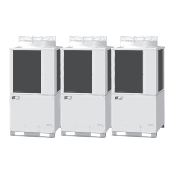
- Page 154 04-218 Airwell-4_1.qxp 01/06/2007 13:10 Page 21 3-WAY FLOW LOGIC Unit Specifications 1. Outdoor Unit 1-3. Multiple Unit Installation Example 4 - 21...
- Page 155 04-218 Airwell-4_1.qxp 01/06/2007 13:11 Page 22 3-WAY FLOW LOGIC Unit Specifications 1. Outdoor Unit 4 - 22...
-
Page 156: Refrigerant Flow Diagram
04-218 Airwell-4_1.qxp 01/06/2007 13:11 Page 23 3-WAY FLOW LOGIC Unit Specifications 1. Outdoor Unit 1-4. Refrigerant Flow Diagram EFL 80-3R410 EFL 100-3R410 EFL 120-3R410 Distribution joint kit High pressure switch Low pressure sensor (Purchased separately) (AC1) Compressor (INV) Compressor separator Balance tube (for 224 –... - Page 157 04-218 Airwell-4_1.qxp 01/06/2007 13:11 Page 24 3-WAY FLOW LOGIC Unit Specifications 1. Outdoor Unit EFL 140-3R410 Distribution joint kit High pressure switch Low pressure sensor (Purchased separately) (AC1) Compressor (INV) Compressor separator (AC2) Balance tube (for 400, 450 model: φ9.52)
- Page 158 01/06/2007 13:11 Page 25 3-WAY FLOW LOGIC Unit Specifications 1. Outdoor Unit 1-5. Noise Criterion Curves EFL 80-3R410, EFL 100-3R410, EFL 120-3R410, EFL 140-3R410, EFL 160-3R410 MODEL : EFL 80-3R410 MODEL : EFL 100-3R410 SOUND LEVEL : SOUND LEVEL : 54.5...
-
Page 159: Way Air-Discharge Semi-Concealed Type
04-218 Airwell-4_2&3.qxp 01/06/2007 13:20 Page 26 3-WAY FLOW LOGIC Unit Specifications 2. 4-Way Air Discharge Semi-concealed Type 2-1. Specifications Unit specifications (A) MODEL No. Indoor Unit ST-NKFL-7 POWER SOURCE 220 - 230 - 240 V / single-phase / 50Hz PERFORMANCE... - Page 160 04-218 Airwell-4_2&3.qxp 01/06/2007 13:20 Page 27 3-WAY FLOW LOGIC Unit Specifications 2. 4-Way Air Discharge Semi-concealed Type Unit specifications (B) MODEL No. Indoor Unit ST-NKFL 9 POWER SOURCE 220 - 230 - 240 V / single-phase / 50Hz PERFORMANCE Cooling...
- Page 161 04-218 Airwell-4_2&3.qxp 01/06/2007 13:20 Page 28 3-WAY FLOW LOGIC Unit Specifications 2. 4-Way Air Discharge Semi-concealed Type Unit specifications (C) ST-NKFL 12 MODEL No. Indoor Unit POWER SOURCE 220 - 230 - 240 V / single-phase / 50Hz PERFORMANCE Cooling...
- Page 162 04-218 Airwell-4_2&3.qxp 01/06/2007 13:20 Page 29 3-WAY FLOW LOGIC Unit Specifications 2. 4-Way Air Discharge Semi-concealed Type Unit specifications (D) ST-NKFL 18 MODEL No. Indoor Unit POWER SOURCE 220 - 230 - 240 V / single-phase / 50Hz PERFORMANCE Cooling...
- Page 163 04-218 Airwell-4_2&3.qxp 01/06/2007 13:20 Page 30 3-WAY FLOW LOGIC Unit Specifications 2. 4-Way Air Discharge Semi-concealed Type Unit specifications (E) ST-NKFL 24 MODEL No. Indoor Unit POWER SOURCE 220 - 230 - 240 V / 1 phase / 50Hz PERFORMANCE...
- Page 164 04-218 Airwell-4_2&3.qxp 01/06/2007 13:20 Page 31 3-WAY FLOW LOGIC Unit Specifications 2. 4-Way Air Discharge Semi-concealed Type Unit specifications (F) ST-NKFL 36 MODEL No. Indoor Unit POWER SOURCE 220 - 230 - 240 V / single-phase / 50Hz PERFORMANCE Cooling...
- Page 165 04-218 Airwell-4_2&3.qxp 01/06/2007 13:20 Page 32 3-WAY FLOW LOGIC Unit Specifications 2. 4-Way Air Discharge Semi-concealed Type Unit specifications (G) MODEL No. Indoor Unit ST-NKFL 48 POWER SOURCE 220 - 230 - 240 V / 1 phase / 50Hz PERFORMANCE...
- Page 166 04-218 Airwell-4_2&3.qxp 01/06/2007 13:20 Page 33 3-WAY FLOW LOGIC Unit Specifications 2. 4-Way Air Discharge Semi-concealed Type Unit specifications (H) MODEL No. Indoor Unit ST-NKFL 60 POWER SOURCE 220 - 230 - 240 V / single-phase / 50Hz PERFORMANCE Cooling...
- Page 167 04-218 Airwell-4_2&3.qxp 01/06/2007 13:20 Page 34 3-WAY FLOW LOGIC Unit Specifications 2. 4-Way Air Discharge Semi-concealed Type 2-2. Major Component Specifications Indoor unit (A) MODEL No. ST-NKFL Source 220 - 230 - 240 V / single-phase / 50 Hz Controller P.C.B. Ass’y CR-SRP50A-B (Microprocessor) Fan (Number…diameter)
- Page 168 04-218 Airwell-4_2&3.qxp 01/06/2007 13:20 Page 35 3-WAY FLOW LOGIC Unit Specifications 2. 4-Way Air Discharge Semi-concealed Type Indoor unit (B) MODEL No. ST-NKFL 9 Source 220 - 230 - 240 V / single-phase / 50 Hz Controller P.C.B. Ass’y CR-SRP50A-B (Microprocessor) Fan (Number…diameter)
- Page 169 04-218 Airwell-4_2&3.qxp 01/06/2007 13:20 Page 36 3-WAY FLOW LOGIC Unit Specifications 2. 4-Way Air Discharge Semi-concealed Type Indoor unit (C) MODEL No. ST-NKFL 12 Source 220 - 230 - 240 V / single-phase / 50 Hz Controller P.C.B. Ass’y CR-SRP50A-B (Microprocessor) Fan (Number…diameter)
- Page 170 04-218 Airwell-4_2&3.qxp 01/06/2007 13:20 Page 37 3-WAY FLOW LOGIC Unit Specifications 2. 4-Way Air Discharge Semi-concealed Type Indoor unit (D) MODEL No. ST-NKFL 18 Source 220 - 230 - 240 V / single-phase / 50 Hz Controller P.C.B. Ass’y CR-SRP50A-B (Microprocessor) Fan (Number…diameter)
- Page 171 04-218 Airwell-4_2&3.qxp 01/06/2007 13:20 Page 38 3-WAY FLOW LOGIC Unit Specifications 2. 4-Way Air Discharge Semi-concealed Type Indoor unit (E) MODEL No. ST-NKFL 24 Source 220 - 230 - 240 V / single-phase / 50 Hz Controller P.C.B. Ass’y CR-SRP50A-B (Microprocessor) Fan (Number…diameter)
- Page 172 04-218 Airwell-4_2&3.qxp 01/06/2007 13:20 Page 39 3-WAY FLOW LOGIC Unit Specifications 2. 4-Way Air Discharge Semi-concealed Type Indoor unit (F) MODEL No. ST-NKFL 36 Source 220 - 230 - 240 V / single-phase / 50 Hz Controller P.C.B. Ass’y CR-SRP50A-B (Microprocessor) Fan (Number…diameter)
- Page 173 04-218 Airwell-4_2&3.qxp 01/06/2007 13:20 Page 40 3-WAY FLOW LOGIC Unit Specifications 2. 4-Way Air Discharge Semi-concealed Type Indoor unit (G) MODEL No. ST-NKFL 48 Source 220 - 230 - 240 V / single-phase / 50 Hz Controller P.C.B. Ass’y CR-SRP50A-B (Microprocessor) Fan (Number…diameter)
- Page 174 04-218 Airwell-4_2&3.qxp 01/06/2007 13:20 Page 41 3-WAY FLOW LOGIC Unit Specifications 2. 4-Way Air Discharge Semi-concealed Type Indoor unit (H) MODEL No. ST-NKFL 60 Source 220 - 230 - 240 V / single-phase / 50 Hz Controller P.C.B. Ass’y CR-SRP50A-B (Microprocessor) Fan (Number…diameter)
- Page 175 04-218 Airwell-4_2&3.qxp 01/06/2007 13:20 Page 42 3-WAY FLOW LOGIC Unit Specifications 2. 4-Way Air Discharge Semi-concealed Type 2-3. Dimensional Data 860 – 910 Ceiling opening dimensions Suspension bolt pitch 4 - 42...
- Page 176 04-218 Airwell-4_2&3.qxp 01/06/2007 13:20 Page 43 3-WAY FLOW LOGIC Unit Specifications 2. 4-Way Air Discharge Semi-concealed Type 4 - 43...
- Page 177 04-218 Airwell-4_2&3.qxp 01/06/2007 13:20 Page 44 3-WAY FLOW LOGIC Unit Specifications 2. 4-Way Air Discharge Semi-concealed Type 2-4. Noise Criterion Curves Both 50Hz and 60Hz ST-NFKL Strong Weak MODEL : ST-NKFL 7, ST-NKFL 9, MODEL : ST-NKFL 24 ST-NKFL 12, ST-NKFL 18...
- Page 178 04-218 Airwell-4_2&3.qxp 01/06/2007 13:20 Page 45 3-WAY FLOW LOGIC Unit Specifications 2. 4-Way Air Discharge Semi-concealed Type 2-5. Air Throw Distance Chart (Indoor temp.: Cooling 27°C, heating 20°C) ST-NKFL ● If an ultra long-life filter or high performance filter (65% by colorimetric method) is installed, the vertical air throw distance for heating and cooling will be approximately 0.2 m less than the values shown in the graph below.
-
Page 179: Way Air Discharge Semi-Concealed Type
04-218 Airwell-4_2&3.qxp 01/06/2007 13:20 Page 46 3-WAY FLOW LOGIC Unit Specifications 3. 2-Way Air Discharge Semi-concealed Type 3-1. Specifications Unit specifications (A) MODEL No. Indoor Unit ST-NK2FL 7 POWER SOURCE 220 - 230 - 240 V / single-phase / 50 Hz... - Page 180 04-218 Airwell-4_2&3.qxp 01/06/2007 13:20 Page 47 3-WAY FLOW LOGIC Unit Specifications 3. 2-Way Air Discharge Semi-concealed Type Unit specifications (B) MODEL No. Indoor Unit ST-NK2FL 9 POWER SOURCE 220 - 230 - 240 V / single-phase / 50 Hz PERFORMANCE...
- Page 181 04-218 Airwell-4_2&3.qxp 01/06/2007 13:20 Page 48 3-WAY FLOW LOGIC Unit Specifications 3. 2-Way Air Discharge Semi-concealed Type Unit specifications (C) MODEL No. Indoor Unit ST-NK2FL 12 POWER SOURCE 220 - 230 - 240 V / single-phase / 50 Hz PERFORMANCE...
- Page 182 04-218 Airwell-4_2&3.qxp 01/06/2007 13:20 Page 49 3-WAY FLOW LOGIC Unit Specifications 3. 2-Way Air Discharge Semi-concealed Type Unit specifications (D) MODEL No. Indoor Unit ST-NK2FL 18 POWER SOURCE 220 - 230 - 240 V / single-phase / 50 Hz PERFORMANCE...
- Page 183 04-218 Airwell-4_2&3.qxp 01/06/2007 13:20 Page 50 3-WAY FLOW LOGIC Unit Specifications 3. 2-Way Air Discharge Semi-concealed Type Unit specifications (E) MODEL No. Indoor Unit ST-NK2FL 24 POWER SOURCE 220 - 230 - 240 V / single-phase / 50 Hz PERFORMANCE...
- Page 184 04-218 Airwell-4_2&3.qxp 01/06/2007 13:20 Page 51 3-WAY FLOW LOGIC Unit Specifications 3. 2-Way Air Discharge Semi-concealed Type 3-2. Major Component Specifications Indoor unit (A) MODEL No. ST-NK2FL 7 Source 220 - 230 - 240 V / single-phase / 50 Hz Controller P.C.B.
- Page 185 04-218 Airwell-4_2&3.qxp 01/06/2007 13:20 Page 52 3-WAY FLOW LOGIC Unit Specifications 3. 2-Way Air Discharge Semi-concealed Type Indoor unit (B) MODEL No. ST-NK2FL 9 Source 220 - 230 - 240 V / single-phase / 50 Hz Controller P.C.B. Ass’y CR-TRP50A-B (Microprocessor) Fan (Number…diameter)
- Page 186 04-218 Airwell-4_2&3.qxp 01/06/2007 13:20 Page 53 3-WAY FLOW LOGIC Unit Specifications 3. 2-Way Air Discharge Semi-concealed Type Indoor unit (C) MODEL No. ST-NK2FL 12 Source 220 - 230 - 240 V / single-phase / 50 Hz Controller P.C.B. Ass’y CR-TRP50A-B (Microprocessor) Fan (Number…diameter)
- Page 187 04-218 Airwell-4_2&3.qxp 01/06/2007 13:20 Page 54 3-WAY FLOW LOGIC Unit Specifications 3. 2-Way Air Discharge Semi-concealed Type Indoor unit (D) MODEL No. ST-NK2FL 18 Source 220 - 230 - 240 V / single-phase / 50 Hz Controller P.C.B. Ass’y CR-TRP50A-B (Microprocessor) Fan (Number…diameter)
- Page 188 04-218 Airwell-4_2&3.qxp 01/06/2007 13:20 Page 55 3-WAY FLOW LOGIC Unit Specifications 3. 2-Way Air Discharge Semi-concealed Type Indoor unit (E) MODEL No. ST-NK2FL 24 Source 220 - 230 - 240 V / single-phase / 50 Hz Controller P.C.B. Ass’y CR-TRP50A-B (Microprocessor) Fan (Number…diameter)
- Page 189 04-218 Airwell-4_2&3.qxp 01/06/2007 13:20 Page 56 3-WAY FLOW LOGIC Unit Specifications 3. 2-Way Air Discharge Semi-concealed Type 3-3. Dimensional Data Indoor unit : 7, 9, 12, 18 Type Refrigerant liquid line (ø6.35) Refrigerant gas line (ø12.7 : 7,9,12, 18 type) Drain connection (25 A.
- Page 190 04-218 Airwell-4_2&3.qxp 01/06/2007 13:20 Page 57 3-WAY FLOW LOGIC Unit Specifications 3. 2-Way Air Discharge Semi-concealed Type Indoor unit : 24 Type Refrigerant liquid line (ø9.52) Refrigerant gas line (ø15.88) Drain connection (25 A. O.D. 32 mm) Power supply entry...
- Page 191 04-218 Airwell-4_2&3.qxp 01/06/2007 13:20 Page 58 3-WAY FLOW LOGIC Unit Specifications 3. 2-Way Air Discharge Semi-concealed Type 3-4. Noise Criterion Curves Both 50Hz and 60Hz ST-NK2FL Strong Weak MODEL : ST-NK2FL 7 MODEL : ST-NK2FL 9, ST-NK2FL 12 SOUND LEVEL :...
- Page 192 04-218 Airwell-4_2&3.qxp 01/06/2007 13:20 Page 59 3-WAY FLOW LOGIC Unit Specifications 3. 2-Way Air Discharge Semi-concealed Type 3-5. Air Throw Distance Chart (Indoor temp.: Cooling 27°C, heating 20°C) ST-NK2FL 7 ST-NK2FL 9, ST-NK2FL 12 Horizontal air throw distance (m) Horizontal air throw distance (m)
-
Page 193: Wall-Mounted Type
04-218 Airwell-4_4-5.qxp 01/06/2007 13:09 Page 60 3-WAY FLOW LOGIC Unit Specifications 4. Wall-Mounted Type 4-1. Specifications Unit specifications (A) MODEL No. Indoor Unit ST-NWFL 7 POWER SOURCE 220 - 230 - 240 V / single-phase / 50 Hz PERFORMANCE Cooling... - Page 194 04-218 Airwell-4_4-5.qxp 01/06/2007 13:09 Page 61 3-WAY FLOW LOGIC Unit Specifications 4. Wall-Mounted Type Unit specifications (B) MODEL No. Indoor Unit ST-NWFL 9 POWER SOURCE 220 - 230 - 240 V / single-phase / 50 Hz PERFORMANCE Cooling Heating Capacity...
- Page 195 04-218 Airwell-4_4-5.qxp 01/06/2007 13:09 Page 62 3-WAY FLOW LOGIC Unit Specifications 4. Wall-Mounted Type Unit specifications (C) MODEL No. Indoor Unit ST-NWFL 12 POWER SOURCE 220 - 230 - 240 V / single-phase / 50 Hz PERFORMANCE Cooling Heating Capacity...
- Page 196 04-218 Airwell-4_4-5.qxp 01/06/2007 13:09 Page 63 3-WAY FLOW LOGIC Unit Specifications 4. Wall-Mounted Type Unit specifications (D) MODEL No. Indoor Unit ST-NWFL 18 POWER SOURCE 220 - 230 - 240 V / single-phase / 50 Hz PERFORMANCE Cooling Heating Capacity...
- Page 197 04-218 Airwell-4_4-5.qxp 01/06/2007 13:09 Page 64 3-WAY FLOW LOGIC Unit Specifications 4. Wall-Mounted Type Unit specifications (E) MODEL No. Indoor Unit ST-NWFL 24 POWER SOURCE 220 - 230 - 240 V / single-phase / 50 Hz PERFORMANCE Cooling Heating Capacity...
- Page 198 04-218 Airwell-4_4-5.qxp 01/06/2007 13:09 Page 65 3-WAY FLOW LOGIC Unit Specifications 4. Wall-Mounted Type 4-2. Major Component Specifications Indoor unit (A) MODEL No. ST-NWFL 7 Source 220 - 230 - 240 V / single-phase / 50 Hz Controller P.C.B. Ass’y CR-KR74GXH56 (Microprocessor) Fan (Number…diameter)
-
Page 199: St-Nffl
04-218 Airwell-4_4-5.qxp 01/06/2007 13:09 Page 66 3-WAY FLOW LOGIC Unit Specifications 4. Wall-Mounted Type Indoor unit (B) MODEL No. ST-NFFL 9 Source 220 - 230 - 240 V / single-phase / 50 Hz Controller P.C.B. Ass’y CR-TRP50A-B (Microprocessor) Fan (Number…diameter) Centrifugal (1 …... -
Page 200: St-Nwfl
04-218 Airwell-4_4-5.qxp 01/06/2007 13:09 Page 67 3-WAY FLOW LOGIC Unit Specifications 4. Wall-Mounted Type Indoor unit (C) MODEL No. ST-NWFL 12 Source 220 - 230 - 240 V / single-phase / 50 Hz Controller P.C.B. Ass’y CR-KR74GXH56 (Microprocessor) Fan (Number…diameter) Cross-flow (1 …... - Page 201 04-218 Airwell-4_4-5.qxp 01/06/2007 13:09 Page 68 3-WAY FLOW LOGIC Unit Specifications 4. Wall-Mounted Type Indoor unit (D) MODEL No. ST-NWFL 18 Source 220 - 230 - 240 V / single-phase / 50 Hz Controller P.C.B. Ass’y CR-KR74GXH56 (Microprocessor) Fan (Number…diameter) Cross-flow (1 …...
- Page 202 04-218 Airwell-4_4-5.qxp 01/06/2007 13:09 Page 69 3-WAY FLOW LOGIC Unit Specifications 4. Wall-Mounted Type Indoor unit (E) MODEL No. ST-NWFL 24 Source 220 - 230 - 240 V / single-phase / 50 Hz Controller P.C.B. Ass’y CR-KR254GXH56 (Microprocessor) Fan (Number…diameter) Cross-flow (1 …...
- Page 203 04-218 Airwell-4_4-5.qxp 01/06/2007 13:09 Page 70 3-WAY FLOW LOGIC Unit Specifications 4. Wall-Mounted Type 4-3. Dimensional Data 7, 9, 12, 18 type Wide tube φ12.7 (length: Approx. 400 mm) Drain and wiring port (φ9.52) Narrow tube φ6.35 (length: Approx. 470 mm) Drain hose VP13 (length: Approx.
- Page 204 04-218 Airwell-4_4-5.qxp 01/06/2007 13:09 Page 71 3-WAY FLOW LOGIC Unit Specifications 4. Wall-Mounted Type 4-4. Noise Criterion Curves ST-NWFL Both 50Hz and 60Hz Strong Weak MODEL : ST-NWFL 7, ST-NWFL 9 ST-NWFL 12 MODEL : ST-NWFL 18 SOUND LEVEL :...
- Page 205 04-218 Airwell-4_4-5.qxp 01/06/2007 13:09 Page 72 3-WAY FLOW LOGIC Unit Specifications 4. Wall-Mounted Type 4-5. Air Throw Distance Chart (Indoor temp.: Cooling 27°C, heating 20°C) ST-NWFL ST-NWFL 18 ST-NWFL 7, ST-NWFL 9 ST-NWFL 12 Horizontal air throw distance (m) Horizontal air throw distance (m) 45°...
-
Page 206: Ceiling-Mounted Type
04-218 Airwell-4_4-5.qxp 01/06/2007 13:09 Page 73 3-WAY FLOW LOGIC Unit Specifications 5. Ceiling-Mounted Type 5-1. Specifications Unit specifications (A) MODEL No. Indoor Unit ST-NPFL 12 POWER SOURCE 220 - 230 - 240 V / single-phase / 50 Hz PERFORMANCE Cooling... - Page 207 04-218 Airwell-4_4-5.qxp 01/06/2007 13:09 Page 74 3-WAY FLOW LOGIC Unit Specifications 5. Ceiling-Mounted Type Unit specifications (B) MODEL No. Indoor Unit ST-NPFL 18 POWER SOURCE 220 - 230 - 240 V / single-phase / 50 Hz PERFORMANCE Cooling Heating Capacity...
- Page 208 04-218 Airwell-4_4-5.qxp 01/06/2007 13:09 Page 75 3-WAY FLOW LOGIC Unit Specifications 5. Ceiling-Mounted Type Unit specifications (C) MODEL No. Indoor Unit ST-NPFL 24 POWER SOURCE 220 - 230 - 240 V / single-phase / 50 Hz PERFORMANCE Cooling Heating Capacity...
- Page 209 04-218 Airwell-4_4-5.qxp 01/06/2007 13:09 Page 76 3-WAY FLOW LOGIC Unit Specifications 5. Ceiling-Mounted Type Unit specifications (D) MODEL No. Indoor Unit ST-NPFL 36 POWER SOURCE 220 - 230 - 240 V / single-phase / 50 Hz PERFORMANCE Cooling Heating 10.6 11.4...
- Page 210 04-218 Airwell-4_4-5.qxp 01/06/2007 13:09 Page 77 3-WAY FLOW LOGIC Unit Specifications 5. Ceiling-Mounted Type Unit specifications (E) MODEL No. Indoor Unit ST-NPFL 48 POWER SOURCE 220 - 230 - 240 V / single-phase / 50 Hz PERFORMANCE Cooling Heating 16.0...
- Page 211 04-218 Airwell-4_4-5.qxp 01/06/2007 13:09 Page 78 3-WAY FLOW LOGIC Unit Specifications 5. Ceiling-Mounted Type 5-2. Major Component Specifications Indoor unit (A) MODEL No. ST-NPFL 12 Source 220 - 230 - 240 V / single-phase / 50 Hz Controller P.C.B. Ass’y CR-SRP50A-B (Microprocessor) Fan (Number…diameter)
- Page 212 04-218 Airwell-4_4-5.qxp 01/06/2007 13:09 Page 79 3-WAY FLOW LOGIC Unit Specifications 5. Ceiling-Mounted Type Indoor unit (B) MODEL No. ST-NPFL 18 Source 220 - 230 - 240 V / single-phase / 50 Hz Controller P.C.B. Ass’y CR-SRP50A-B (Microprocessor) Fan (Number…diameter) Centrifugal (2 …...
- Page 213 04-218 Airwell-4_4-5.qxp 01/06/2007 13:09 Page 80 3-WAY FLOW LOGIC Unit Specifications 5. Ceiling-Mounted Type Indoor unit (C) MODEL No. ST-NPFL 24 Source 220 - 230 - 240 V / single-phase / 50 Hz Controller P.C.B. Ass’y CR-SRP50A-B (Microprocessor) Fan (Number…diameter) Centrifugal (3 …...
- Page 214 04-218 Airwell-4_4-5.qxp 01/06/2007 13:09 Page 81 3-WAY FLOW LOGIC Unit Specifications 5. Ceiling-Mounted Type Indoor unit (D) MODEL No. ST-NPFL 36 Source 220 - 230 - 240 V / single-phase / 50 Hz Controller P.C.B. Ass’y CR-SRP50A-B (Microprocessor) Fan (Number…diameter) Centrifugal (4 …...
- Page 215 04-218 Airwell-4_4-5.qxp 01/06/2007 13:09 Page 82 3-WAY FLOW LOGIC Unit Specifications 5. Ceiling-Mounted Type Indoor unit (E) MODEL No. ST-NPFL 48 Source 220 - 230 - 240 V / single-phase / 50 Hz Controller P.C.B. Ass’y CR-SRP50A-B (Microprocessor) Fan (Number…diameter) Centrifugal (4 …...
- Page 216 04-218 Airwell-4_4-5.qxp 01/06/2007 13:09 Page 83 3-WAY FLOW LOGIC Unit Specifications 5. Ceiling-Mounted Type 5-3. Dimensional Data Length Type Air intake 12, 18 1125 1180 Ceiling side 36, 48 1540 1595 27.5 27.5 Unit: mm (Suspension bolt pitch) Rear (Figure shows view from front)
- Page 217 04-218 Airwell-4_4-5.qxp 01/06/2007 13:09 Page 84 3-WAY FLOW LOGIC Unit Specifications 5. Ceiling-Mounted Type 5-4. Noise Criterion Curves Both 50Hz and 60Hz Strong ST-NPFL Weak MODEL : ST-NPFL 12 MODEL : ST-NPFL 18 SOUND LEVEL : STRONG 35 dB(A) SOUND LEVEL :...
- Page 218 04-218 Airwell-4_4-5.qxp 01/06/2007 13:09 Page 85 3-WAY FLOW LOGIC Unit Specifications 5. Ceiling-Mounted Type 5-5. Air Throw Distance Chart (Indoor temp.: Cooling 27°C, heating 20°C) ST-NPFL ST-NPFL 18 ST-NPFL 12 Horizontal air throw distance (m) Air speed at center Air speed at center...
-
Page 219: Concealed Duct Type
04-218 Airwell-4_6-7.qxp 01/06/2007 13:24 Page 86 3-WAY FLOW LOGIC Unit Specifications 6. Concealed Duct Type 6-1. Specifications Unit specifications (A) MODEL No. Indoor Unit ST-NDLP 7 POWER SOURCE 220 - 230 - 240 V / single-phase / 50 Hz PERFORMANCE... - Page 220 04-218 Airwell-4_6-7.qxp 01/06/2007 13:24 Page 87 3-WAY FLOW LOGIC Unit Specifications 6. Concealed Duct Type Unit specifications (B) MODEL No. Indoor Unit ST-NDLP 9 POWER SOURCE 220 - 230 - 240 V / single-phase / 50 Hz PERFORMANCE Cooling Heating...
- Page 221 04-218 Airwell-4_6-7.qxp 01/06/2007 13:24 Page 88 3-WAY FLOW LOGIC Unit Specifications 6. Concealed Duct Type Unit specifications (C) MODEL No. Indoor Unit ST-NDLP 12 POWER SOURCE 220 - 230 - 240 V / single-phase / 50 Hz PERFORMANCE Cooling Heating...
- Page 222 04-218 Airwell-4_6-7.qxp 01/06/2007 13:24 Page 89 3-WAY FLOW LOGIC Unit Specifications 6. Concealed Duct Type Unit specifications (D) MODEL No. Indoor Unit ST-NDLP 18 POWER SOURCE 220 - 230 - 240 V / single-phase / 50 Hz PERFORMANCE Cooling Heating...
- Page 223 04-218 Airwell-4_6-7.qxp 01/06/2007 13:24 Page 90 3-WAY FLOW LOGIC Unit Specifications 6. Concealed Duct Type Unit specifications (E) MODEL No. Indoor Unit ST-NDLP 24 POWER SOURCE 220 - 230 - 240 V / single-phase / 50 Hz PERFORMANCE Cooling Heating...
- Page 224 04-218 Airwell-4_6-7.qxp 01/06/2007 13:24 Page 91 3-WAY FLOW LOGIC Unit Specifications 6. Concealed Duct Type Unit specifications (F) MODEL No. Indoor Unit ST-NDLP 36 POWER SOURCE 220 - 230 - 240 V / single-phase / 50 Hz PERFORMANCE Cooling Heating 10.6...
- Page 225 04-218 Airwell-4_6-7.qxp 01/06/2007 13:24 Page 92 3-WAY FLOW LOGIC Unit Specifications 6. Concealed Duct Type Unit specifications (G) MODEL No. Indoor Unit ST-NDLP 48 POWER SOURCE 220 - 230 - 240 V / single-phase / 50 Hz PERFORMANCE Cooling Heating 14.0...
- Page 226 04-218 Airwell-4_6-7.qxp 01/06/2007 13:24 Page 93 3-WAY FLOW LOGIC Unit Specifications 6. Concealed Duct Type 6-2. Major Component Specifications Indoor unit (A) MODEL No. ST-NDLP 7 Source 220 - 230 - 240 V / single-phase / 50 Hz Controller P.C.B. Ass’y CR-TRP50A-B (Microprocessor) Fan (Number…diameter)
- Page 227 04-218 Airwell-4_6-7.qxp 01/06/2007 13:24 Page 94 3-WAY FLOW LOGIC Unit Specifications 6. Concealed Duct Type Indoor unit (B) MODEL No. ST-NDLP 9 Source 220 - 230 - 240 V / single-phase / 50 Hz Controller P.C.B. Ass’y CR-TRP50A-B (Microprocessor) Fan (Number…diameter) Centrifugal (1 …...
- Page 228 04-218 Airwell-4_6-7.qxp 01/06/2007 13:24 Page 95 3-WAY FLOW LOGIC Unit Specifications 6. Concealed Duct Type Indoor unit (C) MODEL No. ST-NDLP 12 Source 220 - 230 - 240 V / single-phase / 50 Hz Controller P.C.B. Ass’y CR-TRP50A-B (Microprocessor) Fan (Number…diameter) Centrifugal (1 …...
- Page 229 04-218 Airwell-4_6-7.qxp 01/06/2007 13:24 Page 96 3-WAY FLOW LOGIC Unit Specifications 6. Concealed Duct Type Indoor unit (D) MODEL No. ST-NDLP 18 Source 220 - 230 - 240 V / single-phase / 50 Hz Controller P.C.B. Ass’y CR-TRP50A-B (Microprocessor) Fan (Number…diameter) Centrifugal (1 …...
- Page 230 04-218 Airwell-4_6-7.qxp 01/06/2007 13:24 Page 97 3-WAY FLOW LOGIC Unit Specifications 6. Concealed Duct Type Indoor unit (E) MODEL No. ST-NDLP 24 Source 220 - 230 - 240 V / single-phase / 50 Hz Controller P.C.B. Ass’y CR-TRP50A-B (Microprocessor) Fan (Number…diameter) Centrifugal (2 …...
- Page 231 04-218 Airwell-4_6-7.qxp 01/06/2007 13:24 Page 98 3-WAY FLOW LOGIC Unit Specifications 6. Concealed Duct Type Indoor unit (F) MODEL No. ST-NDLP 36 Source 220 - 230 - 240 V / single-phase / 50 Hz Controller P.C.B. Ass’y CR-TRP50A-B (Microprocessor) Fan (Number…diameter) Centrifugal (3 …...
- Page 232 04-218 Airwell-4_6-7.qxp 01/06/2007 13:24 Page 99 3-WAY FLOW LOGIC Unit Specifications 6. Concealed Duct Type Indoor unit (G) MODEL No. ST-NDLP 48 Source 220 - 230 - 240 V / single-phase / 50 Hz Controller P.C.B. Ass’y CR-TRP50A-B (Microprocessor) Fan (Number…diameter) Centrifugal (3 …...
- Page 233 04-218 Airwell-4_6-7.qxp 01/06/2007 13:24 Page 100 3-WAY FLOW LOGIC Unit Specifications 6. Concealed Duct Type 6-3. Dimensional Data Indoor unit : 7, 9, 12, 18 Type (Air outlet duct flange) (Suspension bolt pitch) Refrigerant liquid line ø6.35 (narrow tube) Refrigerant gas line ø12.7 Upper drain port (O.D.
- Page 234 04-218 Airwell-4_6-7.qxp 01/06/2007 13:24 Page 101 3-WAY FLOW LOGIC Unit Specifications 6. Concealed Duct Type Indoor unit: 24 Type (Air outlet duct flange) (Suspension bolt pitch) Refrigerant liquid line ø9.52 (narrow tube) (Use the tube connector) Refrigerant gas line ø15.88 (wide tube) Upper drain port (O.D.
- Page 235 04-218 Airwell-4_6-7.qxp 01/06/2007 13:24 Page 102 3-WAY FLOW LOGIC Unit Specifications 6. Concealed Duct Type Indoor unit: 36, 48 Type (Air outlet duct flange) (Suspension bolt pitch) Refrigerant liquid line ø9.52 (narrow tube) Refrigerant gas line ø15.88 (wide tube) Upper drain port (O.D. 32 mm) Bottom drain port (O.D.
- Page 236 04-218 Airwell-4_6-7.qxp 01/06/2007 13:24 Page 103 3-WAY FLOW LOGIC Unit Specifications 6. Concealed Duct Type ■ ■ Flange for Air Intake Duct (Field Supply) For Concealed Duct Type Thickness more than T1.2 mm 260 (O.D.) (mm) 200 3 × 200P =...
- Page 237 04-218 Airwell-4_6-7.qxp 01/06/2007 13:24 Page 104 3-WAY FLOW LOGIC Unit Specifications 6. Concealed Duct Type 6-4. Noise Criterion Curves MODEL : ST-NDLP 18 MODEL : ST-NDLP 7 ST-NDLP 9 ST-NDLP 12 SOUND LEVEL : HIGH 29 dB(A), NC 20 / LOW 22 dB(A), NC 13...
- Page 238 04-218 Airwell-4_6-7.qxp 01/06/2007 13:24 Page 105 3-WAY FLOW LOGIC Unit Specifications 6. Concealed Duct Type MODEL : ST-NDLP 36 MODEL : ST-NDLP 48 SOUND LEVEL : HIGH 38 dB(A), NC 30 / LOW 31 dB(A), NC 21 SOUND LEVEL : HIGH 40 dB(A), NC 33 / LOW 33 dB(A), NC 25 CONDITION : Under the unit 1.5 m...
- Page 239 04-218 Airwell-4_6-7.qxp 01/06/2007 13:24 Page 106 3-WAY FLOW LOGIC Unit Specifications 6. Concealed Duct Type 6-5. Increasing the Fan Speed If external static pressure is too great (due to long Electrical component box extension of ducts, for example), the air flow volume Booster cable may drop too low at each air outlet.
-
Page 240: Concealed Duct High Static Pressure Type
04-218 Airwell-4_6-7.qxp 01/06/2007 13:24 Page 107 3-WAY FLOW LOGIC Unit Specifications 7. Concealed Duct High Static Pressure Type 7-1. Specifications Unit specifications (A) MODEL No. Indoor Unit ST-NDHP 24 POWER SOURCE 220 - 230 - 240 V / single-phase / 50 Hz... - Page 241 04-218 Airwell-4_6-7.qxp 01/06/2007 13:24 Page 108 3-WAY FLOW LOGIC Unit Specifications 7. Concealed Duct High Static Pressure Type Unit specifications (B) MODEL No. Indoor Unit ST-NDHP 36 POWER SOURCE 220 - 230 - 240 V / single-phase / 50 Hz...
- Page 242 04-218 Airwell-4_6-7.qxp 01/06/2007 13:24 Page 109 3-WAY FLOW LOGIC Unit Specifications 7. Concealed Duct High Static Pressure Type Unit specifications (C) MODEL No. Indoor Unit ST-NDHP 48 POWER SOURCE 220 - 230 - 240 V / single-phase / 50 Hz...
- Page 243 04-218 Airwell-4_6-7.qxp 01/06/2007 13:24 Page 110 3-WAY FLOW LOGIC Unit Specifications 7. Concealed Duct High Static Pressure Type Unit specifications (D) MODEL No. Indoor Unit ST-NDHP 76 POWER SOURCE 220 - 230 - 240 V / single-phase / 50 Hz...
- Page 244 04-218 Airwell-4_6-7.qxp 01/06/2007 13:24 Page 111 3-WAY FLOW LOGIC Unit Specifications 7. Concealed Duct High Static Pressure Type Unit specifications (E) MODEL No. Indoor Unit ST-NDHP 96 POWER SOURCE 220 - 230 - 240 V / single-phase / 50 Hz...
- Page 245 04-218 Airwell-4_6-7.qxp 01/06/2007 13:24 Page 112 3-WAY FLOW LOGIC Unit Specifications 7. Concealed Duct High Static Pressure Type 7-2. Major Component Specifications Indoor unit (A) MODEL No. ST-NDHP 24 Source 220 - 230 - 240 V / single-phase / 50 Hz Controller P.C.B.
- Page 246 04-218 Airwell-4_6-7.qxp 01/06/2007 13:24 Page 113 3-WAY FLOW LOGIC Unit Specifications 7. Concealed Duct High Static Pressure Type Indoor unit (B) MODEL No. ST-NDHP 36 Source 220 - 230 - 240 V / single-phase / 50 Hz Controller P.C.B. Ass’y CR-TRP50A-B (Microprocessor) Fan (Number…diameter)
- Page 247 04-218 Airwell-4_6-7.qxp 01/06/2007 13:24 Page 114 3-WAY FLOW LOGIC Unit Specifications 7. Concealed Duct High Static Pressure Type Indoor unit (C) MODEL No. ST-NDHP 48 Source 220 - 230 - 240 V / single-phase / 50 Hz Controller P.C.B. Ass’y CR-TRP50A-B (Microprocessor) Fan (Number…diameter)
- Page 248 04-218 Airwell-4_6-7.qxp 01/06/2007 13:24 Page 115 3-WAY FLOW LOGIC Unit Specifications 7. Concealed Duct High Static Pressure Type Indoor unit (D) MODEL No. ST-NDHP 76 Source 220 - 230 - 240 V / single-phase / 50 Hz Controller P.C.B. Ass’y CR-TRP50A-B (Microprocessor) Fan (Number…diameter)
- Page 249 04-218 Airwell-4_6-7.qxp 01/06/2007 13:24 Page 116 3-WAY FLOW LOGIC Unit Specifications 7. Concealed Duct High Static Pressure Type Indoor unit (E) MODEL No. ST-NDHP 96 Source 220 - 230 - 240 V / single-phase / 50 Hz Controller P.C.B. Ass’y CR-TRP50A-B (Microprocessor) Fan (Number…diameter)
- Page 250 04-218 Airwell-4_6-7.qxp 01/06/2007 13:24 Page 117 3-WAY FLOW LOGIC Unit Specifications 7. Concealed Duct High Static Pressure Type 7-3. Dimensional Data Indoor unit : 24, 36, 48 Type 24, 36 type 48 type Refrigerant liquid line (ø9.52) Refrigerant gas line (ø15.88)
- Page 251 04-218 Airwell-4_6-7.qxp 01/06/2007 13:24 Page 118 3-WAY FLOW LOGIC Unit Specifications 7. Concealed Duct High Static Pressure Type Indoor unit : 76, 96 Type Refrigerant liquid line ø9.52 (narrow tube) Refrigerant gas line 76: ø19.05, 96: ø22.22 Power supply outlet...
- Page 252 04-218 Airwell-4_6-7.qxp 01/06/2007 13:24 Page 119 3-WAY FLOW LOGIC Unit Specifications 7. Concealed Duct High Static Pressure Type 7-4. Noise Criterion Curves MODEL : ST-NDHP 24 MODEL : ST-NDHP 36 SOUND LEVEL : HIGH 44 dB(A), NC 38 SOUND LEVEL...
- Page 253 04-218 Airwell-4_6-7.qxp 01/06/2007 13:24 Page 120 3-WAY FLOW LOGIC Unit Specifications 7. Concealed Duct High Static Pressure Type MODEL : ST-NDHP 76 MODEL : ST-NDHP 96 SOUND LEVEL : HIGH 48 dB(A), NC 42 SOUND LEVEL : HIGH 51 dB(A), NC 43 CONDITION : Under the unit 1.5 m...
- Page 254 04-218 Airwell-4_6-7.qxp 01/06/2007 13:24 Page 121 3-WAY FLOW LOGIC Unit Specifications 7. Concealed Duct High Static Pressure Type 7-5. R.A.P. Valve Kit Connect 2 units in parallel for each indoor unit. Attach the R.A.P. valve kit within 30 meters from the indoor unit.
- Page 255 04-218 Airwell-4_6-7.qxp 01/06/2007 13:24 Page 122 3-WAY FLOW LOGIC Unit Specifications 7. Concealed Duct High Static Pressure Type 7-6. Indoor Fan Performance How to Read the Diagram The vertical axis is the EXTERNAL STATIC PRESSURE (mmAq) while the horizontal axis represents the AIR FLOW (m /minute).
- Page 256 04-218 Airwell-4_6-7.qxp 01/06/2007 13:24 Page 123 3-WAY FLOW LOGIC Unit Specifications 7. Concealed Duct High Static Pressure Type Increasing the Fan Speed (96 type only) If external static pressure is too great (due to long Electrical component box extension of ducts, for example), the air flow volume Booster cable may drop too low at each air outlet.
-
Page 257: Floor-Standing Type (Nffl Type)
04-218 Airwell-4_8-9.qxp 01/06/2007 13:25 Page 124 3-WAY FLOW LOGIC Unit Specifications 8. Floor-Standing Type (ST-NFFL Type) 8-1. Specifications Unit specifications (A) MODEL No. Indoor Unit ST-NFFL 7 POWER SOURCE 220 - 230 - 240 V / single-phase / 50 Hz... - Page 258 04-218 Airwell-4_8-9.qxp 01/06/2007 13:25 Page 125 3-WAY FLOW LOGIC Unit Specifications 8. Floor-Standing Type (ST-NFFL Type) Unit specifications (B) MODEL No. Indoor Unit ST-NFFL 9 POWER SOURCE 220 - 230 - 240 V / single-phase / 50 Hz PERFORMANCE Cooling...
- Page 259 04-218 Airwell-4_8-9.qxp 01/06/2007 13:25 Page 126 3-WAY FLOW LOGIC Unit Specifications 8. Floor-Standing Type (ST-NFFL Type) Unit specifications (C) MODEL No. Indoor Unit ST-NFFL 12 POWER SOURCE 220 - 230 - 240 V / single-phase / 50 Hz PERFORMANCE Cooling...
- Page 260 04-218 Airwell-4_8-9.qxp 01/06/2007 13:25 Page 127 3-WAY FLOW LOGIC Unit Specifications 8. Floor-Standing Type (ST-NFFL Type) Unit specifications (D) MODEL No. Indoor Unit ST-NFFL 18 POWER SOURCE 220 - 230 - 240 V / single-phase / 50 Hz PERFORMANCE Cooling...
- Page 261 04-218 Airwell-4_8-9.qxp 01/06/2007 13:25 Page 128 3-WAY FLOW LOGIC Unit Specifications 8. Floor-Standing Type (ST-NFFL Type) Unit specifications (E) MODEL No. Indoor Unit ST-NFFL 24 POWER SOURCE 220 - 230 - 240 V / single-phase / 50 Hz PERFORMANCE Cooling...
- Page 262 04-218 Airwell-4_8-9.qxp 01/06/2007 13:25 Page 129 3-WAY FLOW LOGIC Unit Specifications 8. Floor-Standing Type (ST-NFFL Type) 8-2. Major Component Specifications Indoor unit (A) MODEL No. ST-NFFL 7 Source 220 - 230 - 240 V / single-phase / 50 Hz Controller P.C.B. Ass’y CR-TRP50A-B (Microprocessor) Fan (Number…diameter)
- Page 263 04-218 Airwell-4_8-9.qxp 01/06/2007 13:25 Page 130 3-WAY FLOW LOGIC Unit Specifications 8. Floor-Standing Type (ST-NFFL Type) Indoor unit (B) MODEL No. ST-NFFL 9 Source 220 - 230 - 240 V / single-phase / 50 Hz Controller P.C.B. Ass’y CR-TRP50A-B (Microprocessor) Fan (Number…diameter)
- Page 264 04-218 Airwell-4_8-9.qxp 01/06/2007 13:25 Page 131 3-WAY FLOW LOGIC Unit Specifications 8. Floor-Standing Type (ST-NFFL Type) Indoor unit (C) MODEL No. ST-NFFL 12 Source 220 - 230 - 240 V / single-phase / 50 Hz Controller P.C.B. Ass’y CR-TRP50A-B (Microprocessor) Fan (Number…diameter)
- Page 265 04-218 Airwell-4_8-9.qxp 01/06/2007 13:25 Page 132 3-WAY FLOW LOGIC Unit Specifications 8. Floor-Standing Type (ST-NFFL Type) Indoor unit (D) MODEL No. ST-NFFL 18 Source 220 - 230 - 240 V / single-phase / 50 Hz Controller P.C.B. Ass’y CR-TRP50A-B (Microprocessor) Fan (Number…diameter)
- Page 266 04-218 Airwell-4_8-9.qxp 01/06/2007 13:25 Page 133 3-WAY FLOW LOGIC Unit Specifications 8. Floor-Standing Type (ST-NFFL Type) Indoor unit (E) MODEL No. ST-NFFL 24 Source 220 - 230 - 240 V / single-phase / 50 Hz Controller P.C.B. Ass’y CR-TRP50A-B (Microprocessor) Fan (Number…diameter)
- Page 267 04-218 Airwell-4_8-9.qxp 01/06/2007 13:25 Page 134 3-WAY FLOW LOGIC Unit Specifications 8. Floor-Standing Type (ST-NFFL Type) 8-3. Dimensional Data Indoor unit : 9, 12, 18, 24 Type Size Narrow Wide tube tube Type 1065 6.35 12.7 7, 9, 12, 18...
- Page 268 04-218 Airwell-4_8-9.qxp 01/06/2007 13:25 Page 135 3-WAY FLOW LOGIC Unit Specifications 8. Floor-Standing Type (ST-NFFL Type) 8-4. Noise Criterion Curves MODEL : ST-NFFL 7, ST-NFFL 9 MODEL : ST-NFFL 12 SOUND LEVEL : HIGH 33 dB(A), NC 27 SOUND LEVEL : HIGH 39 dB(A), NC 33...
- Page 269 04-218 Airwell-4_8-9.qxp 01/06/2007 13:25 Page 136 3-WAY FLOW LOGIC Unit Specifications 8. Floor-Standing Type (ST-NFFL Type) 8-5. Air Throw Distance Chart Model: 7, 9 Type Model: 12 Type AIR OUTLET HEATING CEILING AIR OUTLET HEATING CEILING COOLING COOLING HEATING HEATING...
-
Page 270: Way Air Discharge Semi-Concealed Slim Type (Nksfl Type)
04-218 Airwell-4_8-9.qxp 01/06/2007 13:25 Page 137 3-WAY FLOW LOGIC Unit Specifications 9. 1-Way Air Discharge Semi-concealed Slim Type (ST-NKSFL Type) 9-1. Specifications Unit specifications (A) MODEL No. Indoor Unit ST-NKSFL 9 POWER SOURCE 220 - 230 - 240 V / single-phase / 50 Hz... - Page 271 04-218 Airwell-4_8-9.qxp 01/06/2007 13:25 Page 138 3-WAY FLOW LOGIC Unit Specifications 9. 1-Way Air Discharge Semi-concealed Slim Type (ST-NKSFL Type) Unit specifications (B) MODEL No. Indoor Unit ST-NKSFL 12 POWER SOURCE 220 - 230 - 240 V / single-phase / 50 Hz...
- Page 272 04-218 Airwell-4_8-9.qxp 01/06/2007 13:25 Page 139 3-WAY FLOW LOGIC Unit Specifications 9. 1-Way Air Discharge Semi-concealed Slim Type (ST-NKSFL Type) Unit specifications (C) MODEL No. Indoor Unit ST-NKSFL 18 POWER SOURCE 220 - 230 - 240 V / single-phase / 50 Hz...
- Page 273 04-218 Airwell-4_8-9.qxp 01/06/2007 13:25 Page 140 3-WAY FLOW LOGIC Unit Specifications 9. 1-Way Air Discharge Semi-concealed Slim Type (ST-NKSFL Type) Unit specifications (D) MODEL No. Indoor Unit ST-NKSFL 24 POWER SOURCE 220 - 230 - 240 V / single-phase / 50 Hz...
- Page 274 04-218 Airwell-4_8-9.qxp 01/06/2007 13:25 Page 141 3-WAY FLOW LOGIC Unit Specifications 9. 1-Way Air Discharge Semi-concealed Slim Type (ST-NKSFL Type) 9-2. Major Component Specifications Indoor unit (A) MODEL No. ST-NKSFL 9 Source 220 - 230 - 240 V / single-phase / 50 Hz Controller P.C.B.
- Page 275 04-218 Airwell-4_8-9.qxp 01/06/2007 13:25 Page 142 3-WAY FLOW LOGIC Unit Specifications 9. 1-Way Air Discharge Semi-concealed Slim Type (ST-NKSFL Type) Indoor unit (B) MODEL No. ST-NKSFL 12 Source 220 - 230 - 240 V / single-phase / 50 Hz Controller P.C.B. Ass’y CR-TRP50A-B (Microprocessor) Fan (Number…diameter)
- Page 276 04-218 Airwell-4_8-9.qxp 01/06/2007 13:25 Page 143 3-WAY FLOW LOGIC Unit Specifications 9. 1-Way Air Discharge Semi-concealed Slim Type (ST-NKSFL Type) Indoor unit (C) MODEL No. ST-NKSFL 18 Source 220 - 230 - 240 V / single-phase / 50 Hz Controller P.C.B. Ass’y CR-TRP50A-B (Microprocessor) Fan (Number…diameter)
- Page 277 04-218 Airwell-4_8-9.qxp 01/06/2007 13:25 Page 144 3-WAY FLOW LOGIC Unit Specifications 9. 1-Way Air Discharge Semi-concealed Slim Type (ST-NKSFL Type) Indoor unit (D) MODEL No. ST-NKSFL 24 Source 220 - 230 - 240 V / single-phase / 50 Hz Controller P.C.B. Ass’y CR-TRP50A-B (Microprocessor) Fan (Number…diameter)
- Page 278 04-218 Airwell-4_8-9.qxp 01/06/2007 13:25 Page 145 3-WAY FLOW LOGIC Unit Specifications 9. 1-Way Air Discharge Semi-concealed Slim Type (ST-NKSFL Type) 9-3. Dimensional Data Indoor unit : 9, 12, 18, 24 Type 9, 12, 18 Type 1233 1193 1089 1003 24 Type...
- Page 279 04-218 Airwell-4_8-9.qxp 01/06/2007 13:25 Page 146 3-WAY FLOW LOGIC Unit Specifications 9. 1-Way Air Discharge Semi-concealed Slim Type (ST-NKSFL Type) 9-4. Noise Criterion Curves MODEL : ST-NKSFL 9 MODEL : ST-NKSFL 18 ST-NKSFL 12 SOUND LEVEL : HIGH 43 dB(A), NC 41 / LOW 33 dB(A), NC 27...
- Page 280 04-218 Airwell-4_8-9.qxp 01/06/2007 13:25 Page 147 3-WAY FLOW LOGIC Unit Specifications 9. 1-Way Air Discharge Semi-concealed Slim Type (ST-NKSFL Type) 9-5. Air Throw Distance Chart ST-NKSFL 9, ST-NKSFL 12 HORIZONTAL DISTANCE (m) AXIS AIR VELOCITY ST-NKSFL 18 HORIZONTAL DISTANCE (m)
-
Page 281: Test Run
04-218 Airwell-5.qxp 01/06/2007 13:26 Page 1 Test Run Contents 5. TEST RUN 1.Test Run ............. . . 5-2 1-1. -
Page 282: Test Run Procedure
04-218 Airwell-5.qxp 01/06/2007 13:26 Page 2 Test Run 1. Test Run 1-1. Test Run Procedure Recheck the items to check before the test run. Items to Check Before the Test Run 1. Turn the remote power switch on at least 5 hours before the test, in order Have the outdoor sub units been connected? to energize the crank case heater. -
Page 283: Meaning Of Alarm Messages
04-218 Airwell-5.qxp 01/06/2007 13:26 Page 3 Test Run 1. Test Run 1-2. Meaning of Alarm Messages Table of Self-Diagnostics Functions and Description of Alarm Displays. Alarm messages are indicated by the blinking of LED 1 and 2 (D72, D75) on the outdoor unit PCB. They are also displayed on the wired remote controller. - Page 284 04-218 Airwell-5.qxp 01/06/2007 13:26 Page 4 Test Run 1. Test Run Alarm Possible cause of malfunction message Thermal protector in indoor unit fan motor is activated. <<P01>> Activation of Protective device in outdoor unit protective is activated. Improper wiring connections of ceiling panel.
- Page 285 04-218 Airwell-5.qxp 01/06/2007 13:26 Page 5 Test Run 1. Test Run Alarm Alarm messages displayed on system controller message Low oil level. Protective device for Comp. No. 1 oil sensor Oil sensor fault. compressor is (Disconnection, etc.) Comp. No. 2 oil sensor...
-
Page 286: Electrical Data
04-218 Airwell-6.qxp 01/06/2007 13:22 Page 1 Electrical Data Contents 6. ELECTRICAL DATA 1. Outdoor Unit ............6-2 2. -
Page 287: Outdoor Unit
04-218 Airwell-6.qxp 01/06/2007 13:22 Page 2 Electrical Data 1. Outdoor Unit (1) Electric Wiring Diagram EFL 80-3R410, EFL 100-3R410, EFL 120-3R410 6 - 2... - Page 288 04-218 Airwell-6.qxp 01/06/2007 13:23 Page 3 Electrical Data 1. Outdoor Unit Schematic Diagram EFL 80-3R410, EFL 100-3R410, EFL 120-3R410 6 - 3...
- Page 289 04-218 Airwell-6.qxp 01/06/2007 13:23 Page 4 Electrical Data 1. Outdoor Unit (2) Electric Wiring Diagram EFL 140-3R410, EFL 160-3R410 6 - 4...
- Page 290 04-218 Airwell-6.qxp 01/06/2007 13:23 Page 5 Electrical Data 1. Outdoor Unit Schematic Wiring Diagram EFL 140-3R410, EFL 160-3R410 6 - 5...
-
Page 291: Indoor Unit
04-218 Airwell-6.qxp 01/06/2007 13:23 Page 6 Electrical Data 2. Indoor Unit (1) Electric Wiring Diagram ST-NKFL 7, ST-NKFL 9, ST-NKFL 12, ST-NKFL 18, ST-NKFL 24, ST-NKFL 36, ST-NKFL 48, ST-NKFL 60 6 - 6... - Page 292 04-218 Airwell-6.qxp 01/06/2007 13:23 Page 7 Electrical Data 2. Indoor Unit Schematic Diagram ST-NKFL 7, ST-NKFL 9, ST-NKFL 12, ST-NKFL 18, ST-NKFL 24, ST-NKFL 36, ST-NKFL 48, ST-NKFL 60 6 - 7...
-
Page 293: St-Nk2Fl
04-218 Airwell-6.qxp 01/06/2007 13:23 Page 8 Electrical Data 2. Indoor Unit (2) Electric Wiring Diagram ST-NK2FL 7, ST-NK2FL 9, ST-NK2FL 12, ST-NK2FL 18, ST-NK2FL 24 6 - 8... - Page 294 04-218 Airwell-6.qxp 01/06/2007 13:23 Page 9 Electrical Data 2. Indoor Unit Schematic Wiring Diagram ST-NK2FL 7, ST-NK2FL 9, ST-NK2FL 12, ST-NK2FL 18, ST-NK2FL 24 6 - 9...
- Page 295 04-218 Airwell-6.qxp 01/06/2007 13:23 Page 10 Electrical Data 2. Indoor Unit (3) Electric Wiring Diagram ST-NKSFL 9, ST-NKSFL 12, ST-NKSFL 18 6 - 10...
-
Page 296: St-Nwfl
04-218 Airwell-6.qxp 01/06/2007 13:23 Page 11 Electrical Data 2. Indoor Unit Schematic Wiring Diagram ST-NWFL 7, ST-NWFL 9, ST-NWFL 12, ST-NWFL 18 6 - 11... - Page 297 04-218 Airwell-6.qxp 01/06/2007 13:23 Page 12 Electrical Data 2. Indoor Unit (4)-1 Electric Wiring Diagram ST-NWFL 7, ST-NWFL 9, ST-NWFL 12, ST-NWFL 18 6 - 12...
- Page 298 04-218 Airwell-6.qxp 01/06/2007 13:23 Page 13 Electrical Data 2. Indoor Unit Schematic Wiring Diagram ST-NWFL 7, ST-NWFL 9, ST-NWFL 12, ST-NWFL 18 6 - 13...
- Page 299 04-218 Airwell-6.qxp 01/06/2007 13:23 Page 14 Electrical Data 2. Indoor Unit (4-2) Electric Wiring Diagram ST-NWFL 24 6 - 14...
- Page 300 04-218 Airwell-6.qxp 01/06/2007 13:23 Page 15 Electrical Data 2. Indoor Unit Schematic Wiring Diagram ST-NWFL 24 6 - 15...
-
Page 301: St-Npfl
04-218 Airwell-6.qxp 01/06/2007 13:23 Page 16 Electrical Data 2. Indoor Unit (5) Electric Wiring Diagram ST-NPFL 12, ST-NPFL 18, ST-NPFL 24, ST-NPFL 36, ST-NPFL 48 6 - 16... - Page 302 04-218 Airwell-6.qxp 01/06/2007 13:23 Page 17 Electrical Data 2. Indoor Unit Schematic Wiring Diagram ST-NPFL 12, ST-NPFL 18, ST-NPFL 24, ST-NPFL 36, ST-NPFL 48 6 - 17...
-
Page 303: St-Ndlp
04-218 Airwell-6.qxp 01/06/2007 13:23 Page 18 Electrical Data 2. Indoor Unit (6) Electric Wiring Diagram ST-NDLP 7, ST-NDLP 9, ST-NDLP 12, ST-NDLP 18, ST-NDLP 24, ST-NDLP 36, ST-NDLP 48 6 - 18... - Page 304 04-218 Airwell-6.qxp 01/06/2007 13:23 Page 19 Electrical Data 2. Indoor Unit Schematic Wiring Diagram ST-NDLP 7, ST-NDLP 9, ST-NDLP 12, ST-NDLP 18, ST-NDLP 24, ST-NDLP 36, ST-NDLP 48 6 - 19...
- Page 305 04-218 Airwell-6.qxp 01/06/2007 13:23 Page 20 Electrical Data 2. Indoor Unit (7)-1 Electric Wiring Diagram ST-NDHP 24 6 - 20...
- Page 306 04-218 Airwell-6.qxp 01/06/2007 13:23 Page 21 Electrical Data 2. Indoor Unit Schematic Wiring Diagram ST-NDHP 24 6 - 21...
- Page 307 04-218 Airwell-6.qxp 01/06/2007 13:23 Page 22 Electrical Data 2. Indoor Unit (7)-2 Electric Wiring Diagram ST-NDHP 36 6 - 22...
- Page 308 04-218 Airwell-6.qxp 01/06/2007 13:23 Page 23 Electrical Data 2. Indoor Unit Schematic Wiring Diagram ST-NDHP 36 6 - 23...
- Page 309 04-218 Airwell-6.qxp 01/06/2007 13:23 Page 24 Electrical Data 2. Indoor Unit (7)-3 Electric Wiring Diagram ST-NDHP 48 6 - 24...
- Page 310 04-218 Airwell-6.qxp 01/06/2007 13:23 Page 25 Electrical Data 2. Indoor Unit Schematic Wiring Diagram ST-NDHP 48 6 - 25...
- Page 311 04-218 Airwell-6.qxp 01/06/2007 13:23 Page 26 Electrical Data 2. Indoor Unit (7)-4 Electric Wiring Diagram ST-NDHP 76 6 - 26...
- Page 312 04-218 Airwell-6.qxp 01/06/2007 13:23 Page 27 Electrical Data 2. Indoor Unit Schematic Wiring Diagram ST-NDHP 76 6 - 27...
- Page 313 04-218 Airwell-6.qxp 01/06/2007 13:23 Page 28 Electrical Data 2. Indoor Unit (7)-5 Electric Wiring Diagram ST-NDHP 96 6 - 28...
- Page 314 04-218 Airwell-6.qxp 01/06/2007 13:23 Page 29 Electrical Data 2. Indoor Unit Schematic Wiring Diagram ST-NDHP 96 6 - 29...
- Page 315 04-218 Airwell-6.qxp 01/06/2007 13:23 Page 30 Electrical Data 2. Indoor Unit (8) Electric Wiring Diagram ST-NDHP 96 6 - 30...
-
Page 316: St-Nffl
04-218 Airwell-6.qxp 01/06/2007 13:23 Page 31 Electrical Data 2. Indoor Unit Schematic Wiring Diagram ST-NFFL 7, ST-NFFL 9, ST-NFFL 12, ST-NFFL 18, ST-NFFL 24 6 - 31... -
Page 317: Pcb And Functions
04-218 Airwell-7.qxp 01/06/2007 13:25 Page 1 PCB and Functions Contents 7. PCB AND FUNCTIONS 1. Outdoor Unit Control PCB ..........7-2 2. -
Page 318: Outdoor Unit Control Pcb
04-218 Airwell-7.qxp 01/06/2007 13:25 Page 2 PCB and Functions 1. Outdoor Unit Control PCB 7-1. Outdoor Unit Control PCB EFL 120-3R410 S002 LED1 LED2 S005 S004 S006 S007 S003 CN100 CN101 CN102 CN104 CN003 CN022 CN103 7 - 2... - Page 319 04-218 Airwell-7.qxp 01/06/2007 13:25 Page 3 PCB and Functions 1. Outdoor Unit Control PCB 7-2. Functions (for EFL 120-3R410) 2P plug (white): Automatic address setting pin Automatic address setting • Short-circuit this pin for 1 second or longer to automatically set the addresses at the (CN100) indoor units that are connected to that outdoor unit and are within the same system.
- Page 320 04-218 Airwell-7.qxp 01/06/2007 13:25 Page 4 PCB and Functions 1. Outdoor Unit Control PCB LED (red × 2) LED1, 2 DO72, DO75 • LED 1 and 2 blink alternately while automatic address setting is in progress. • Display the alarm contents for alarms which were detected by the outdoor unit.
- Page 321 04-218 Airwell-7.qxp 01/06/2007 13:25 Page 5 PCB and Functions 1. Outdoor Unit Control PCB Table 1. Setting the System Address [S002: Rotary switch (black), S003: 2P DIP (blue)] (for CR-CR1154GDXH8) S003 setting S002 setting (system Outdoor system address No. address switch)
- Page 322 04-218 Airwell-7.qxp 01/06/2007 13:25 Page 6 PCB and Functions 1. Outdoor Unit Control PCB ■ ■ For AC Fan Motor (CR-TRP50A-B) OC (CN040) EMG (CN044) Varistor (VA041) DISP (CN72) GRL (CN20) EXCT (CN73) CHK (CN71) POWER LED FANDRIVE (CN32) T10 (CN61)
-
Page 323: Indoor Unit Control Pcb Switches And Functions
04-218 Airwell-7.qxp 01/06/2007 13:25 Page 7 PCB and Functions 2. Indoor Unit Control PCB Switches and Functions Indoor Unit Control PCB Switches and Functions Indoor unit control PCB T10: 6P plug (yellow): Used for remote control. (Refer to the remote control section.) -
Page 324: St-Nwfl
04-218 Airwell-7.qxp 01/06/2007 13:25 Page 8 PCB and Functions 2. Indoor Unit Control PCB Switches and Functions Explanation of Functions Indoor Unit Control PCB 7-3. CR1 (for ST-NWFL 7, ST-NWFL 18) (Wall Mounted) If the fuse (F002) has CHK (test) pin... -
Page 325: St-Nwfl
04-218 Airwell-7.qxp 01/06/2007 13:25 Page 9 PCB and Functions 2. Indoor Unit Control PCB Switches and Functions 7-4. CR1 (for ST-NWFL 24) (Wall Mounted) If the fuse (F002) has blown, determine the CHK (test) pin cause and correct it. Then change the socket... - Page 326 04-218 Airwell-7.qxp 01/06/2007 13:25 Page 10 PCB and Functions 2. Indoor Unit Control PCB Switches and Functions 7-5. CR2 (for ST-NWFL 7, ST-NWFL 24) (Wall Mounted) Control circuit fuse (F201) T20 plug TRANS-S plug OP1 plug 7 - 10...
- Page 327 04-218 Airwell-7.qxp 01/06/2007 13:25 Page 11 PCB and Functions 2. Indoor Unit Control PCB Switches and Functions 7-6. Explanation of Functions 6P flag (yellow): Used for remote control. ➀ ➁ (CN105) Control items: Start/stop input Remote controller prohibit input (For remote control) ➂...
- Page 328 04-218 Airwell-7.qxp 01/06/2007 13:25 Page 12 PCB and Functions 2. Indoor Unit Control PCB Switches and Functions OPTION 6P (white): Outputs external signals as shown in the figure below. (CN014) Relay (DC 12V, field supply) (Note) Fan signal OPTION (white)
Need help?
Do you have a question about the EFL 80-3R410 and is the answer not in the manual?
Questions and answers