
Related Manuals for Airwell CKD 036


Summary of Contents for Airwell CKD 036
- Page 1 CKD DCI Series Indoor Units Outdoor Units CKD 036 GCD 036 CKD 045 GC 43 REFRIGERANT R410A HEAT PUMP JANUARY ─ 2010...
- Page 2 LIST OF EFFECTIVE PAGES LIST OF EFFECTIVE PAGES Note: Changes in the pages are indicated by a “Revision#” in the footer of each effected page (when none indicates no changes in the relevant page). All pages in the following list represent effected/ non effected pages divided by chapters.
-
Page 3: Table Of Contents
TABLE OF CONTENTS Table of Contents INTRODUCTION ....................1-1 PRODUCT DATA SHEET ..................2-1 RATING CONDITIONS ..................3-1 OUTLINE DIMENSIONS ..................4-1 PERFORMANCE DATA & PRESSURE CURVES ..........5-1 SOUND LEVEL CHARACTERISTICS ..............6-1 ELECTRICAL DATA ....................7-1 WIRING DIAGRAMS .....................8-1 REFRIGERATION DIAGRAMS ................9-1 10. TUBING CONNECTIONS ..................10-1 11. -
Page 4: Introduction
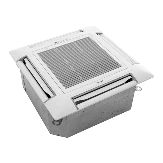
General The new GCD 036 DCR, GC 36-43 DC INVERTER split unit range comprises the following RC (heat pump) models: • CKD 036 • CKD 045 Remote control compatibility The units are compatible with remote controls RC3, RC4, RCW1, RCW2, RC7. - Page 5 1.3.1. CASSETTE - CKD The CKD 036, 045 DCI 90x90cm is part of the new indoor unit family of cassette units. It is an extension of the present 60x60 CK/CN DCI family. These new models will support the light commercial line and addition to the 4-5-6HP family.
- Page 6 For further details, please refer the Optional Accessories, Chapter 16. Inbox Documentation Each unit includes its own installation and operation manuals. 1.10 Matching Table 1.10.1 R410A INDOOR UNITS OUTDOOR UNITS MODEL CKD 036 CKD 045 √ GCD036 DCR √ GC 43 DCI SM CKDDCI 2-A.3 GB...
-
Page 7: Product Data Sheet
PRODUCT DATA SHEET PRODUCT DATA SHEET CKD 036 DCI / GCD 036 DCR Model Indoor Unit CKD 036 DCI Model Outdoor Unit GCD 036 DCR Installation Method CASSETTE Characteristics Units Cooling Heating Btu/hr 30,700 (8,900 – 34,120) 35,150 (8,200 – 39,250) Capacity - Nominal (Minimum ~ Maximum) 9.0 (2.6 –... - Page 8 PRODUCT DATA SHEET CKD 045 DCI / GC 43 DCI Model Indoor Unit CKD 045 DCI Model Outdoor Unit GC 43 DCI Installation Method CASSETTE Characteristics Units Cooling Heating Btu/hr 41,300 (8,550 – 44,350) 46,050 (8,850 – 49,150) Capacity - Nominal (Minimum ~ Maximum) 12.1 (2.5 –...
-
Page 9: Rating Conditions
RATING CONDITIONS RATING CONDITIONS Standard conditions in accordance with ISO 5151 and ISO 13253 (for ducted units) and EN 14511. Cooling: Indoor: C DB 19 C WB Outdoor: 35 C DB Heating: Indoor: C DB Outdoor: 7 C DB 6 C WB Operating Limits Indoor... -
Page 10: Outline Dimensions
OUTLINE DIMENSIONS OUTLINE DIMENSIONS Indoor Unit: CKD 036 / 045 DCI Necessary room outlet inlet outlet Drain side Tubing side ground 780 (Hook-location) 840 (Body) 880 (Ceiling hole) 950 (Panel) (Unit: mm) SM CKDDCI 2-A.3 GB... - Page 11 OUTLINE DIMENSIONS Outdoor Unit: GCD 036 DCR Outdoor Unit: GC 43 DCI SM CKDDCI 2-A.3 GB...
-
Page 12: Performance Data & Pressure Curves
PERFORMANCE DATA & PRESSURE CURVES PERFORMANCE DATA & PRESSURE CURVES CKD 036 DCI / GCD 036 DCR 5.1.1 Cooling Capacity (kW) ID COIL ENTERING AIR DB/WB TEMPERATURE [ºC] OD COIL ENTERING AIR DATA 22/15 24/17 27/19 29/21 32/23 DB TEMPERATURE [ºC]... -
Page 13: Heating Capacity
PERFORMANCE DATA & PRESSURE CURVES 5.1.3 Heating Capacity ID COIL ENTERING AIR DB TEMPERATURE [°C] OD COIL ENTERING AIR DB/WB DATA TEMPERATURE [°C] 6.56 6.10 5.64 -15/-16 2.06 2.27 2.48 7.30 6.84 6.38 -10/-12 2.48 2.69 2.90 7.85 7.40 6.94 -7/-8 2.80 3.01... - Page 14 PERFORMANCE DATA & PRESSURE CURVES 5.1.5 Pressure Curves Cooling – Technician Mode) 5.8.5.1 Cooling Suction Pressure - Cooling (Technician Mode) 1400 1300 1200 32/23 1100 29/21 1000 27/19 24/17 22/15 Outdoor DB Temperature [°C] Discharge Pressure - Cooling (Technician Mode) 4000 3750 3500...
- Page 15 PERFORMANCE DATA & PRESSURE CURVES 5.1.5.2 Heating Suction Pressure - Heating (Technician Mode) 1300 1200 1100 1000 Outdoor WB Temperature [°C] Discharge Pressure - Heating (Technician Mode) 4000 3750 3500 3250 3000 2750 2500 2250 2000 1750 1500 1250 1000 Outdoor WB Temperature [°C] SM CKDDCI 2-A.3 GB...
- Page 16 PERFORMANCE DATA & PRESSURE CURVES CKD 045 DCI / GC 43 DCI 5.2.1 Cooling Capacity (kW) ID COIL ENTERING AIR DB/WB TEMPERATURE [C] OD COIL 22/15 24/17 27/19 29/21 32/23 ENTERING AIR DB DATA TEMPERATURE [C] 80 - 110 % of nominal -10 –...
- Page 17 PERFORMANCE DATA & PRESSURE CURVES 5.2.3 Heating Capacity ID COIL ENTERING AIR DB TEMPERATURE [°C] OD COIL ENTERING AIR DB/WB DATA TEMPERATURE [°C] 8.53 7.93 7.34 -15/-16 3.09 3.41 3.72 9.49 8.90 8.30 -10/-12 3.73 4.04 4.35 10.22 9.62 9.02 -7/-8 4.20 4.52...
- Page 18 PERFORMANCE DATA & PRESSURE CURVES 5.2.5 Pressure Curves Cooling – Technician Mode) 5.2.5.1 Cooling Suction Pressure - Cooling (Technician Mode) 1400 1300 1200 32/23 1100 29/21 1000 27/19 24/17 22/15 Outdoor DB Temperature [°C] Discharge Pressure - Cooling (Technician Mode) 4000 3750 3500...
- Page 19 PERFORMANCE DATA & PRESSURE CURVES 5.2.5.2 Cooling Suction Pressure - Heating (Technician Mode) 1300 1200 1100 1000 Outdoor WB Temperature [°C] Discharge Pressure - Heating (Technician Mode) 4000 3750 3500 3250 3000 2750 2500 2250 2000 1750 1500 1250 1000 Outdoor WB Temperature [°C] SM CKDDCI 2-A.3 GB...
- Page 20 PERFORMANCE DATA & PRESSURE CURVES Capacity Correction Factor for Tubing Length 5.3.1 Cooling 1.05 1.00 0.95 0.90 0.85 0.80 0.75 Tubing Lenght [m] 5.3.2 Heating 1.05 1.00 0.95 0.90 0.85 0.80 0.75 Tubing Lenght [m] SM CKDDCI 2-A.3 GB...
- Page 21 PERFORMANCE DATA & PRESSURE CURVES Pressure Correction Factor for Tubing Length 5.4.1 Cooling Pressure vs Tubing Lenght (COOLING) 1.02 1.02 1.00 1.00 Cooling Discharge Pressure 0.98 0.98 0.96 0.96 0.94 0.94 Cooling Suction Pressure 0.92 0.92 0.90 0.90 0.88 0.88 0.86 0.86 Total Tubing Length [m]...
- Page 22 PERFORMANCE DATA & PRESSURE CURVES Calculation Example Outdoor Unit GC 43 DCI Indoor Unit DLS 43 DCI Operation Mode Cooling Mode Conditions Indoor 22CDB/15WB Conditions Oudoor 30CDB Tubing length Cooling Capacity calculation: Total Cooling Capacity (TC) [KW] = Capacity in conditions table x F Cooling Capacity in table [KW] Tubing Length Factor (F Corrected Capacity [KW]...
-
Page 23: Sound Level Characteristics
SOUND LEVEL CHARACTERISTICS SOUND LEVEL CHARACTERISTICS Indoor Units Test Scheme Figure 1 Sound Pressure Level Spectrum (Measured as Figure 1) CKD 036 CKD 045 FAN SPEED LINE SM CKDDCI 2-A.3 GB... -
Page 24: Outdoor Units
SOUND LEVEL CHARACTERISTICS Outdoor Units 1.0 m Center for Unit Figure 2 Sound Pressure Level Spectrum ( Measured as Figure 2) GCD 036 DCR Cooling GCD 036 DCR Heating GC 43 DCI Cooling GC 43 DCI Heating SM CKDDCI 2-A.3 GB... -
Page 25: Electrical Data
ELECTRICAL DATA ELECTRICAL DATA Single Phase Units MODEL GCD 036 DCR GC 43 DCI Power Supply 1PH – 230V – 50 Hz Outdoor Indoor Outdoor Indoor Connected to Max Current Inrush Current Starting Current Circuit Breaker Power Supply Wiring 3 X 4.0 mm 3 X 1.5 mm 3 X 6.0 mm 3 X 1.5 mm... -
Page 26: Wiring Diagrams
WIRING DIAGRAMS WIRING DIAGRAMS Indoor Unit: CKD 036, CKD 045 DCI 202052390039 SM CKDDCI 2-A.3 GB... -
Page 27: Wiring Diagrams
WIRING DIAGRAMS Outdoor Units: GCD 036 DCR DANGER!! ATTENTION: HIGH DC VOLTAGE!! FOR INDOOR UNIT ELECTRICAL WIRING REFER TO INDOOR UNIT DIAGRAM DO NOT TOUCH WHILE LED'S ARE ON AND 3 MINUTE AFTER POWER OFF LINE FILTER POWER SUPPLY(BY INSTALLER): Chock Coils 1PH/230VAC / 50Hz... - Page 28 WIRING DIAGRAMS 1PH UNITS POWER SUPPLY TO OUTDOOR (10.0, 12.5, 14.0 Kw units) Indoor Unit Power Supply Cable Main Power Breaker Outdoor Unit Interconnecting cable (2x0.75mm Power Interconnecting Cable (3x1.5mm Wireless remote Control Display Unit Display Connector Power Breaker (*by installer) Control Cable** Sensor Wire with connector Room Temperature Sensor...
- Page 29 WIRING DIAGRAMS 1PH UNITS POWER SUPPLY TO OUTDOOR and INDOOR UNIT SEPERATELY (10.0, 12.5, 14.0 Kw units) 1. Indoor Unit 2. Power Supply Cable 3. Main Power Breaker 4. Outdoor Unit 5. Interconnecting cable (2x0.75mm 6. Wireless remote Control 7. Display Unit 8.
-
Page 30: Refrigeration Diagrams
REFRIGERATION DIAGRAMS REFRIGERATION DIAGRAMS Heat Pump Models 9.1.1 CKD 036, CKD 045 Cooling mode Heating mode SM CKDDCI 2-A.3 GB... -
Page 31: Tubing Connections
TUBING CONNECTIONS TUBING CONNECTIONS TUBE (Inch) ¼” ⅜” ½” ⅝” ¾” TORQUE (Nm) Flare Nuts 15-18 40-45 60-65 70-75 80-85 Valve Cap 13-20 13-20 18-25 18-25 40-50 Service Port Cap 11-13 11-13 11-13 11-13 11-13 Valve Protection Cap-end Refrigerant Valve Port (use Allen wrench to open/close) Valve Protection Cap Refrigerant Valve Service Port Cap... -
Page 32: Optional Accessories
OPTIONAL ACCESSORIES OPTIONAL ACCESSORIES 11.1 RCW Wall Mounted Remote Control 11.1.1 The RCW wall mounted remote control can be fitted to a large range and models, It can be used as IR (wirless mode) or wired controler.the RCW can control up to15 indoor units using the same settings (on its wired aplication). - Page 33 OPTIONAL ACCESSORIES 11.2 RCW2 Wall Mounted Remote Control 11.2.1 The RCW2 wall mounted remote controler is a wired controler that can provide affective controling management up to 15 different settings and temp’ zones. The RCW2 can be connected up to a max’ of 32 units,allowing a max wiring length of 1000m for application on WNG LED indoor units an additional interface PCB is needed.
- Page 34 OPTIONAL ACCESSORIES 11.3 Base Heater PN: 439878 Before starting the heaters connection verify that the unit is disconnected from main power supply!! BASE HEATERT INSTALLATION INSTRUCTIONS Check the installation manual for further information The kit includes 1. One 70W PT heating element. 2.
- Page 35 OPTIONAL ACCESSORIES 11-4 SM CKDDCI 2-A.3 GB...
- Page 36 OPTIONAL ACCESSORIES 11.4 Crank Case Heater PN: 190443 Before starting the heaters connection verify that the unit is disconnected from main power supply!! CRANK CASE HEATERS INSTALLATION INSTRUCTIONS Check the installation manual for further information The kit includes 1. One 50W heating element. 2.
-
Page 37: Room Thermostat
OPTIONAL ACCESSORIES 11.5 Room Thermostat Room Thermostat kit PN: 442298 Thermistor with connector PN: 442296 Before starting the connection verify that the unit is disconnected from main power supply!! ROOM THERMOSTAT INSTALLATION INSTRUCTIONS Check the installation manual for further information Supplied components list: Item Thermostat box... -
Page 38: Control System
CONTROL SYSTEM CONTROL SYSTEM 12.1 Abbreviations Abbreviation Definition Air Conditioner Building Management System Compressor Current Crankcase Heater COMP Compressor Compressor Top Temperature sensor DC Inverter E²PROM, EEP Erase Enable Programmable Read Only Memory Electronic Expansion Valve Heating Element Human Machine Interface High Pressure Switch Heat Sink Temperature sensor Hertz (1/sec) –... -
Page 39: Product Overview
CONTROL SYSTEM 12.2 Product Overview 12.2.1 Block Diagram Line Filter Compressor 230VAC Driver Inrush Control (4-5HP Only) Speed AC Current DC Current Inrush Driver Control Control ODU Controller OFAN Control Display OFAN IDU Controller Control Communication IFAN Input Dry- Temp. 230V Contacts Control... - Page 40 CONTROL SYSTEM 12.2.2 Controller overview 12.2.2.1 Main Controller Outdoor Unit Driver Comm. Inrush IDU-ODU Comm. Power Supply + Ground M2L (PC Fuse 3.15A DIP-SWITCHES OFAN_UP ALARM Power Shedding STAND BY NIGHT OFAN_DN HIGH PRESSURE LOW PRESSURE BASE HEATER DISPLAY HMI FLASH PORT CRANK CASE HEATER (7-segments)
- Page 41 CONTROL SYSTEM 12.2.2.3 Display Board Display Display Board PCB Legend Name Plate Cooling LED Heating LED Push Button (Mode) Timer LED STBY LED Operation LED IR Receiver Buzzer 10. Display Port Connection 12.2.3 Control Features 12.2.3.1 Compressor DC brush less and sensor less motor inverter driven compressor. 12.2.3.2 Compressor Drive DC inverter module to drive compressor.
- Page 42 CONTROL SYSTEM 12.2.3.5 EEV Expansion valve operated by step motor which controls the size of the orifice. 12.2.3.6 HMI Consists of Four “7-Segments” + four push buttons for display, monitoring and setup features. 12.2.3.7 Dry Contacts Dry contacts are used to interface the system with an external building management system (BMS).
- Page 43 CONTROL SYSTEM 12.3 General Operating Rules Communication with Indoor Unit 12.3.1 12.3.1.1 Communication Failures Definition 12.3.1.1.1 Bad Communication’ fault The system keeps a balance of a good/bad communication packet ratio. When the ratio becomes high the system enters ‘Bad Communication’ fault. The system recovers from that fault when the ratio becomes small again.
-
Page 44: Indoor Unit Control
CONTROL SYSTEM 12.4 Indoor Unit Control 12.4.1 Load calculation LOAD is calculated according to the difference between actual room temperature and user set point temperature by PI control. In high/ medium/ low indoor fan user setting, unit will operate fan in selected speed. In AutoFan user setting, fan speed will be adjusted automatically according to the calculated LOAD. - Page 45 CONTROL SYSTEM 12.4.2.3 Indoor fan control – Heat Mode 12.4.2.3.1 IFAN Operation in set speed When in heat mode, including protections and except Deicing, IFAN will be working according to the graph below. 12.4.2.3.2 IFAN Operation in Auto Fan Mode IFAN speed will be set automatically according to Load by the following graph: IFAN Speed...
-
Page 46: Cooling Mode
CONTROL SYSTEM 12.4.3 Cooling Mode 12.4.3.1 Cooling Mode – General Mode Definition Mode: COOL, AUTO (at Cooling) Temp: Selected desired temperature. Fan: LOW, MED, HIGH, TURBO, AUTO. Timer: I-FEEL: ON or OFF Room Temperature, RT, is detected by: RAT in normal operation, or RCT (R/C sensor) in I-FEEL mode. - Page 47 CONTROL SYSTEM 12.4.3.3 Sequence Diagrams Maintaining room temp at desired level by comparing RT and SPT with user defined IFAN speed. (RT - SPT) [ C] COMP Speed COMP Speed decrease increase COMP OFAN Speed OFAN Speed increase decrease OFAN User Fan Speed IFAN 12-10...
- Page 48 CONTROL SYSTEM 12.4.4 Heating Mode 12.4.4.1 Heating - General Mode Definition Mode: HEAT, AUTO (at heating) Temp: Selected desired temperature Fan: LOW, MED, HIGH, TURBO, AUTO. Timer: Any I-FEEL: ON or OFF Room Temperature, RT, is detected by: RAT in normal operation, or RCT (R/C sensor) in I-FEEL mode.
- Page 49 CONTROL SYSTEM 12.4.4.3 Sequence Diagram Maintains room temp. at desired level by comparing RAT or RCT to SPT. (RT - SPT) [ C] COMP Speed COMP Speed decrease increase COMP OFAN Speed OFAN Speed increase decrease OFAN User Fan Speed IFAN See IFAN Rules 12.4.4.4 Temperature Compensation...
- Page 50 CONTROL SYSTEM 12.4.5 Automatic Cooling or Heating 12.4.5.1 Automatic Cooling or Heating - General Mode Definition Mode: AUTO Temp: Selected desired temperature Fan: Timer: I-FEEL: ON or OFF 12.4.5.2 Control Functions Switching-temperature between Cooling and Heating is SPT ± 3 When the AUTO Mode is started with SPT +/-0 C, the unit will not select Auto Heat or Auto Cool mode immediately.
- Page 51 CONTROL SYSTEM 12.4.6 Dry Mode 12.4.6.1 DRY - General Mode Definition Mode: Temp: Selected desired temperature Fan: LOW (automatically selected by software) Timer: I-FEEL: ON or OFF 12.4.6.2 Control function COMP Operation In general – the operation is set by the NLOAD calculation in indoor unit side.
-
Page 52: Sleep Mode
CONTROL SYSTEM 12.4.6.3 Sequence Diagrams Reduce room humidity with minimum temp. fluctuations by operating in Cool Mode with LOW speed IFAN. RAT-SPT IFAN Low IFANOffTimeDry IFANOnTimeDry Note 1 Note 1 NLOAD NLOAD Note 1 ExtraNLOADDry,127 } min{MaxNLOADIF1C + MaxNLOADIF1C Min(ICT,ICTE) ICTLowLimitDry ICTHighLimitDry 12.4.7... -
Page 53: Forced Operation
CONTROL SYSTEM In HEAT or AUTO HEAT modes, the SPT adjustment is negative (from 0 to -3 In other modes, there is no SPT adjustment. The SPT adjustment is cancelled when the Sleep mode is cancelled. If OFF-timer is active, the unit may go to SB before or after 7 hours of sleep operation. -
Page 54: Mode Setting
CONTROL SYSTEM 12.4.10 Indoor Unit Dry Contact Indoor unit Dry contact has two alternative functions that are selected by J9 (Dip-Switch). Function Contact = Open Contact = Short Presence Detector Connection No action – normal operation (Default) Forced to STBY “Presence Detector”... -
Page 55: Compressor Speed Control
CONTROL SYSTEM 12.5.2 Compressor Speed Control 12.5.2.1 Compressor Min On/Off time Compressor minimum OFF time is 3 minutes except during Deicing protection. Compressor minimum ON time is 3 minutes, minimum ON time is ignored during protections, and when unit is turned to STBY. 12.5.2.2 Compressor Startup When started, compressor speed reaches certain level (usually 30÷40 RPS) and will not go below that during the first 5 minutes of compressor operation except when compressor forced... - Page 56 CONTROL SYSTEM 12.5.2.8 Speed Step Limitations The compressor speed have some step limitations which it will not go above them for few minuits after startup. 12.5.2.9 Compressor shutdown Procedure There are 2 procedures for compressor shutdown: 1. Immediate shutdown – compressor is stopped on the spot. 2.
- Page 57 CONTROL SYSTEM 12.5.3.6 EEV opening determination in normal run mode The target EEV value is the sum of open loop value (OL) and a result of the accumulative correction values (CV). The EEV corrections are calculated every EEVCVTConst seconds. 12.5.4 Outdoor Fan Speed Control 12.5.4.1 Speed Definition The outdoor fans can work in 16 speed states controlled by OMT sensor in cool mode and ICT...
- Page 58 CONTROL SYSTEM 12.5.8 Compressor internal heating coil Operation 6HP and 4HP DCR units. The crank case heater operates only when compressor is off and according to CTT and OAT. 12.5.9 Thermodynamic Protections 12.5.9.1 Protection level definition Five protection levels are defined: Normal –...
- Page 59 CONTROL SYSTEM 12.5.10 Deicing 12.5.10.1 Deicing Starting Conditions Deicing operation will start when either one of the following conditions exist: Case 1: OCT is 8 degree lower then the ambient temp and the minimum time from the last deicer is passed. Case 2: OCT is 12 degree lower then the ambient temp and 30 minutes from the last deicer wa passed.
- Page 60 CONTROL SYSTEM 12.5.11.1 1 Level Logic Level Don’t care Normal Don’t care Overflow Overflow when Overflow when unit is ON unit is OFF Overflow Water Level Normal OPER BLINK NLOAD is NLOAD forced to 0 PUMP 8 min 8 min 8 min 12.5.12 High/Low Pressure Protection...
-
Page 61: User Interface
CONTROL SYSTEM 12.6.2 Technician mode procedure Indoor unit will enter technician test at high indoor fan speed. The outdoor unit will be working normally (according to the run mode control logic) except the following changes: o The dry contacts inputs will be ignored. o Protections will be operative for stop compressor only. -
Page 62: Main Menu
CONTROL SYSTEM 12.7.2 Main Menu Mode (Cl / Ht / SB) Technician Test (tt) Technician Test Cool (ttC) Technician Test Heat (ttH) Diagnostics (dIA) Outdoor Unit (OdU) First Fault Code Second Fault Code Third Fault Code Forth Fault Code Fifth Fault Code Indoor Unit (IdU) First Fault Code Second Fault Code... - Page 63 CONTROL SYSTEM Notes 1. The default presentation will be the mode of the unit (Cool/Heat/Stby). 2. In diagnostics menu: xx means failure code two numbers. Maximum 5 faults are presented for each unit (each IDUs/ODU). When no faults, a “----“ sign will be shown.
- Page 64 CONTROL SYSTEM 12.7.3 Status (Sub Menu) Status (StAt) Value [°C] Operation Mode Cool Heat Load Nload Value Family settings (FS) Family+Model Operation Mode Cool Heat Deicing OFAN UP Value [x10RPM] OFAN DN Value [x10RPM] Cool Heat Speed Value [RPS] Value [°C] Value [°C] Value [°C] Value [°C]...
- Page 65 CONTROL SYSTEM Notes: For the temperature display, when a thermistor is shorted or disconnected it shows FLT (FLt), when it is disabled it shows DIS (dis). It’s possible to present a number between 999 and 99,999 by alternating between two numbers (each number is presented for 1 second).
- Page 66 CONTROL SYSTEM 12.7.4.2 TPT Sub-Menu 12.7.4.3 Pump Down Test procedure Pump Down is used to evacuate the refrigerant back to the ODU in case of need to dis-connect the indoor unit or the inter-connecting piping for repair. Start the operation by navigating the HMI. A/C will start operate.
- Page 67 CONTROL SYSTEM 12.7.4.4 OFAN Test procedure Start the operation by navigating the HMI. Both OFANs will start operation. After about 30 sec the fans will be shut off. If any of the OFANs are not operating, check the OFANs and the Main board. Replace if faulty.
- Page 68 CONTROL SYSTEM 12.7.4.10 Gas Block Test procedure This test is used for technician to check the blockage within the system. The test is operates in heat mode and the technician should close the liquid valve manually. Start the operation by navigating the HMI. Note - The test is not operable when OAT<5C.
- Page 69 CONTROL SYSTEM 12.8 Jumper/DIP-Switch Setting 12.8.1 Jumper/DIP-Switch Definition 0 = Open (Disconnected) 1 = Close (Shorted) 12.8.2 IDU Jumpers/DIP-Switch DNG / EMD / CD / NFC 12.8.2.1 Self test Jumper/DIP – J1 Position Status Description Open (Disconnected) Normal Operation (Default) Close (Shorted) Self Test enabled Used for internal production line testing.
- Page 70 CONTROL SYSTEM 12.8.2.5 Presence Detector/DIP – J9 Position Status Description Open (Disconnected) Presence detector enabled (Default) Close (Shorted) NA (Not to be used) 12.8.3 ODU Jumpers 12.8.3.1 Self test Jumper/DIP – J1 Position Status Description Open (Disconnected) Normal Operation (Default) Close (Shorted) Self Test enabled Used for internal production line testing.
- Page 71 CONTROL SYSTEM 12.8.4 Dip-Switch Setting Table ODU 4HP C.R. ODU 4HP ODU 5HP ODU 6HP DNG100 DNG125 EMD100 EMD125 CD140 NFC 100 NFC 125 IDU NKN J9 J11 NKN100 NKN125 12-34 SM CKDDCI 2-A.3 GB...
- Page 72 CONTROL SYSTEM 12.8.5 Remote Control DIP Switch Settings SETTING SWITCH STATUS DEFINITION RC4 / RC4i / RC7 NO. 1 NO. 2 NO. 3 NO. 4 RC - all modes of operation ST - COOL, FAN, DRY modes active HEAT COOL, FAN, DRY modes active Auto Mode, FAN modes active Temp.
- Page 73 CONTROL SYSTEM 12.9 System Parameters 12.9.1 General Parameters for All Models Name Default Value Units minute MinOFFTime minute MinONTime RPS/min HzDown1 RPS/min HzDown2 minute DImin minute DImax minute TimeD minute DTmin minute DTmax minute minute CTMRUP minute second HSTOHDelta1 HSTOHDelta2 second EEVCVTConst minute...
- Page 74 CONTROL SYSTEM 12.9.2 ODU Model Dependent Parameters Name Unit GC 43 GC 036 MinFreqC MaxFreqC MinFreqH MaxFreqH Step1Freq Step2Freq Step3Freq *10RPM NightRPM °C CTTOH1 °C CTTOH2 °C CTTOH3 °C CTTOH4 ACCOC1 23.6 17.0 ACCOC2 24.2 17.6 ACCOC3 24.6 18.2 ACCOC4 25.0 19.0 DCCOC1...
- Page 75 CONTROL SYSTEM 12.9.3 Indoor Units SW Parameters Parameters defining the indoor fan speed as a function of Indoor Coil temperature in heat mode (ICT): 12.9.3.1 Parameters for defrost protection: ICTST Speed ICT to stop indoor fan ICTVLSpeed ICT to go down to very low speed ICTLSpeed ICT to start in very low speed ICTHSpeed...
-
Page 76: Troubleshooting
TROUBLESHOOTING TROUBLESHOOTING 13.1 Precaution, Advise and Notice Items 13.1.1 High voltage in Indoor and Outdoor unit electrical assembly Open the Outdoor unit controller assembly only after one minute from power off. Whole controller assembly, including the wires, connected to the Outdoor unit may have the potential hazard voltage when power is on. - Page 77 TROUBLESHOOTING 13.2 General System Failures and Corrective Actions SYMPTOM / PROBABLE CORRECTIVE ACTION PROBLEM CAUSE Indoor unit No Power Check supply voltage to main terminals L and N supply with volt meter. No supply from Check fuse at the connection wiring on outdoor outdoor unit terminals (see Electrical Scheme 9.4) Indoor unit power...
- Page 78 TROUBLESHOOTING SYMPTOM / PROBABLE CORRECTIVE ACTION PROBLEM CAUSE Indoor unit Water leakage from drainage tube is Check and open drainage tube indoor unit blocked Outdoor unit No power Check supply voltage to main terminals L and N supply with volt meter. Check all supply wiring to controller and Miss-wiring Outdoor unit display...
- Page 79 TROUBLESHOOTING SYMPTOM / PROBABLE CORRECTIVE ACTION PROBLEM CAUSE Unit size not Check if the size chosen for the complete match the load room(s) load is enough or need bigger units Piping size Check if piping is installed correctly and proper not matching diameter size and total length is according to system...
- Page 80 TROUBLESHOOTING SYMPTOM / PROBABLE CORRECTIVE ACTION PROBLEM CAUSE Electronic Check for any fault code shown on display control board and act accordingly (13.4) EEV problem Check EEV (13.5.12) Refrigerant Check refrigeration system (13.3) leakage Indoor coil block Clean filters and/or remove block Compressor is over Indoor fan Check indoor fan motor and capacitor (13.5.19)
- Page 81 TROUBLESHOOTING SYMPTOM / PROBABLE CORRECTIVE ACTION PROBLEM CAUSE Other home appliances operation is faulty such as noise appears in the television picture, interference by Check for EMC problems (13.5.20.2) or the picture is the A/C unit distorted or static occurs in the radio sound Specific problems...
- Page 82 TROUBLESHOOTING Problem OCT is disconnected OCT is shorted CTT is disconnected CTT is shorted HST is disconnected (when enabled) HST is shorted (when enabled) OAT is disconnected OAT is shorted OMT is disconnected OMT is shorted IPM Fault Bad EEPROM DC under voltage DC over voltage AC under voltage...
- Page 83 TROUBLESHOOTING 13.4.2 Outdoor unit diagnostics and corrective actions Fault Name Fault Description Corrective Action OCT is disconnected OCT is shorted CTT is disconnected CTT is shorted HST is disconnected Thermistor not connected (when enabled) or damaged Check Thermistor (13.5.13) HST is shorted (when enabled) OAT is disconnected OAT is shorted...
- Page 84 TROUBLESHOOTING Fault Name Fault Description Corrective Action Check power supply to driver No Communication to Driver fault Check driver communication Driver (13.5.16) Current sensor Fault Driver fault Replace Compressor Driver Check that the airflow around the ODU is free and the fan is running Heat sink Over Compressor stopped due free...
- Page 85 TROUBLESHOOTING Fault Name Fault Description Corrective Action Normally no action is required If the problem persists for more than twice on each hour, check for refrigerant clog. High pressure Compressor stopped due Check the switch operation (13.5.14) protection to high pressure protection Check the EEV (13.5.12) Check the Outdoor fans (13.5.9) Check the Indoor fans (13.5.19)
- Page 86 TROUBLESHOOTING Fault Name RT-1 is disconnected RT-1 is shorted RT-2 is disconnected RT-2 is shorted … Reserved Communication mismatch ...
- Page 87 TROUBLESHOOTING Fault Probable Cause Corrective Action Normally no action is required If the problem persists for more than twice on each hour, Check for any fault code shown on outdoor unit display board Compressor stopped Outdoor Unit and act accordingly (13.4) due to outdoor unit Protection Check the EEV (13.5.12)
- Page 88 TROUBLESHOOTING 13.5 Procedures for checking Main Parts 13.5.1 Discharge DC Voltage High voltage!!! Wait for DC voltage to be discharged before re touching any part of the driver to avoid electric shock. Check to ensure that DC voltage has reduced to below 50VDC, if not, keep waiting until it does.
- Page 89 TROUBLESHOOTING Use a digital multi meter in diode checking function Connect the “V” side of the tester to the “P1” terminal of driver and the “COM” side of the tester to “R” and “S” of driver, measure the diode voltage. Voltage should be “OL”...
- Page 90 TROUBLESHOOTING Connect the “V” side of the tester to the “P” terminal of driver and the “COM” side of the tester to “U”, “V” and “W” of driver, measure the diode voltage. Voltage should be “OL” (Over Load). Connect the “COM“ side of the tester to the “N” terminal of driver and the “V”...
- Page 91 TROUBLESHOOTING Connect the “COM“ side of the tester to the “N” terminal of driver and the “V” side of the tester to “T/RB” of driver, measure the diode voltage. Voltage should be “OL” (Over Load). Replacing driver - (14.1.15) 13.5.5.2 GC 60 DCI Remove all the terminals of the driver before checking.
- Page 92 TROUBLESHOOTING Connect the “COM“ side of the tester to the “CAPA+” terminal of driver and the “V” side of the tester to “U”, “V” and “W” of driver, measure the diode voltage. Voltage should be 0.4~0.8VDC. CAPA- CAPA+ Connect the “V” side of the tester to the “CAPA+” terminal of driver and the “COM”...
- Page 93 TROUBLESHOOTING 13.5.6 Checking PFC Chock coil 1) Check PFC chock connections – repair if needed. 2) Visually check to see any burn marks on the wires – replace the chock(s) if needed. 3) Disconnect the chock from the driver and check if the 2 ending wires of each chock are shorted (continuity check) –...
- Page 94 TROUBLESHOOTING OFAN_UP OFAN_DN Control voltage 3)b Check motor 4) Check motor current OFAN_UP OFAN_UP OFAN_DN OFAN_DN Supply voltage Control voltage 3)a Check motor 3)c Check motor Replacing outdoor unit fan motor - (14.1.6) Replacing main board - (14.1.13) 13.5.10 Checking Compressor 1) Check Compressor connections - Repair if needed.
- Page 95 TROUBLESHOOTING COMPESSOR 18.0 3) Check Compressor motor current Replacing compressor- (14.1.10) 13.5.11 Checking Reverse Valve (RV) The RV has two parts, Solenoid and valve. 1) Disconnect the RV connector from the main board and operate the unit in heating mode, check the voltage between two pins of reverse valve connector on the controller, normal voltage is 230VAC - if no power supply to RV, replace outdoor main board.
- Page 96 TROUBLESHOOTING OAT, OCT, OMT, ICT, RAT, HST Chart R-T Table =10k 25°C =3977K 25/85°C 1000.0 100.0 10.0 Temperature [C] CTT Chart R-T Table =50k 25°C =3977K 25/85°C 1000.0 100.0 10.0 Temperature [C] Replacing thermistor - (14.1.11, 14.1.12, 14.2.9) Replacing main board - (14.1.13) 13-21 SM CKDDCI 2-A.3 GB...
- Page 97 TROUBLESHOOTING 13.5.14 Checking High Pressure Switch (HPS) 1) Disconnect HPS connector from the main board and check resistance between the 2 pins of the HPS connector – if shorted the HPS is OK, otherwise replace HPS. Replacing HPS - (14.1.9) 13.5.15 Checking Low Pressure Switch (LPS) 1) Disconnect LPS connector from the main board and check resistance between the 2 pins of the...
- Page 98 TROUBLESHOOTING 13.5.20 Checking for electromagnetic interference (EMC problems) 13.5.20.1 EMC interference to the A/C unit Locations most susceptible to interference 1) Locations near broadcast stations where there are strong electromagnetic waves. 2) Locations near amateur radio (short wave) stations. 3) Locations near electronic sewing machines and arc-welding machines. Problem: 1) The unit may stop suddenly during operation.
-
Page 99: Servicing
SERVICING SERVICING 14.1 Outdoor Unit TURN OFF ALL POWER SOURCE BEFORE HANDLING THE UNIT Note: To reassemble perform the procedures in reverse. 14.1.1 Removing Service (front) panel Remove the 8 fixing screws and slide the service (front) panel downwards to remove it. Note: Do not flip the panel forward on the top side as not to damage the controller. - Page 100 SERVICING 14.1.3 Removing side panel Remove the top cover as in above 14.1.2. Remove the 2 screws holding the electrical plastic cover and disconnect the power supply cords. Remove the 9 fixing screws and take out the side panel. Removing Electrical Cover Removing side panel 14.1.4 Removing Air Outlet Grille(s)
- Page 101 SERVICING 14.1.6 Removing Outdoor Fan Motor Remove the outdoor fan according to 14.1.5. Disconnect the motor connector from the main board. Cut the nylon ties holding the motor cable. Remove the four (4) fixing screws for the motor. NOTES for re-assemble the motor: When mounting the motor, ensure the cables point downwards.
- Page 102 SERVICING 14.1.9 Removing Refrigeration parts Refrigeation parts: Expansion valve, Reversing valve, high pressure switch, etc. Remove the refrigerant from the unit by a pumping machine via the 2 valves. Note: open the valves gradually and leave them only partially open for as long as the refrigerant exerts from the unit.
- Page 103 SERVICING Disconnect Removing Compressor Insulation Removing Compressor 14.1.11 Removing Tubing Thermistors Remove the service front panel according to 14.1.1. Remove the side and top panels according to 14.1.2, 14.1.3 Check to ensure that LEDs and display board are OFF. Disconnect the thermistor connector from the main board.
- Page 104 SERVICING 14.1.13 Removing main board 14.1.13.1 GC 36-43-60 DCI Remove the service front panel according to 14.1.1. Check to ensure that LEDs and display board are OFF. Disconnect all connectors from the main board. Squeeze the 8 spacers head with Long- Nose Pliers and pull out the board.
- Page 105 SERVICING 14.1.14 Removing Electrical assembly 14.1.14.1 GC 36-43-60 DCI Remove the service front panel according to 14.1.1. Remove the side and top panels according to 14.1.2, 14.1.3. Check to ensure that LEDs and display board are OFF. Disconnect the following connectors from the main board: RV, thermistors (4), HPS and EEV. Remove the compressor electrical cover.
- Page 106 SERVICING 14.1.14.2 GCD 036 DCR Remove the service front panel according to 14.1.1. Remove the side and top panels according to 14.1.2. Check to ensure that LEDs and display board are OFF. Disconnect the connectors from the main board. Disconnect the compressor cable connector. Remove the chock coils wires from the chock terminal block.
- Page 107 SERVICING 14.1.15.2 GC 60 DCI Remove the electrical assembly according to 14.1.14. Remove the three (4) screws fixing the main board panel to the assembly and take the panel out. Remove the earth tab connection from the line filter. Remove the five (5) screws fixing the terminal panel to the assembly and take the panel out.
- Page 108 SERVICING 14.1.16 Re-assembling driver module 14.1.16.1 GC 36-43 DCI Wipe out the heat sink and the driver plate with cloth soaked with alcohol. Wipe out the heat sink screw holes as well by inserting the cloth deeply into the holes but beware not to damage the screwing paths.
- Page 109 SERVICING 14.1.17.2 GC 60 DCI Remove the chock coils wires from the chock terminal block. 2. Remove the terminal block holde. 3. Remove the 2 screws for each chock coil to release the chock coils from the partition Removing Chocks Coils 14.1.17.3 GCD 036 DCR Remove the chock coil wires from the chock terminal block.
- Page 110 SERVICING 14.1.19 Removing Line Filter board 14.1.19.1 GC 36-43 DCI Perform the driver module removal procedure in 14.1.15 from 1 to 4 and #6 but first release N and L wires from the line filter. Squeeze the 7 spacers head with Long-Nose Pliers and pull out the board.
-
Page 111: Exploded Views And Spare Parts Lists
EXPLODED VIEWS AND SPARE PARTS LISTS EXPLODED VIEWS AND SPARE PARTS LISTS 15.1 Indoor Unit: CKD 036, CKD 045 DCI - Exploded View (Unit`s) SM CKDDCI 2-A.3 GB 15-1... - Page 112 EXPLODED VIEWS AND SPARE PARTS LISTS 15.1.1 Indoor Unit: CKD 036, CKD 045 DCI - Exploded View (Panel`s) 15-2 SM CKDDCI 2-A.3 GB...
- Page 113 EXPLODED VIEWS AND SPARE PARTS LISTS 15.2 Indoor Unit: CKD 036 DCI - Spare Part List Item Description Quan. P0000371694 (S1004)(RoHS) Grill/Airwell P0000371695 (RoHS) Filter /NKN 202301300044 (RoHS) Water-Level Switch Assy. 201109990016 Front panel/Airwell 202401100017 3.5uF/450V P2 Capacitor for fan motor 201552390005 Evaporator Assy./NKN80...
- Page 114 EXPLODED VIEWS AND SPARE PARTS LISTS 15.3 Indoor Unit: CKD 045 DCI - Spare Part Item Description Quan. P0000371694 (S1004)(RoHS) Grill/Airwell P0000371695 (RoHS) Filter /NKN 202301300044 (RoHS) Water-Level Switch Assy. 201109990016 Front panel/Airwell 202401100961 5.0uF/450V P2 Capacitor for fan motor 201552390006 Evaporator Assy./NKN125...
- Page 115 EXPLODED VIEWS AND SPARE PARTS LISTS 15.4 Outdoor Units: GC 43 DCI - Exploded View 15.4.1 Outdoor Unit General Assembly SM CKDDCI 2-A.3 GB 15-5...
- Page 116 EXPLODED VIEWS AND SPARE PARTS LISTS 15.4.2 Outdoor Unit Tubing Assembly 15-6 SM CKDDCI 2-A.3 GB...
- Page 117 EXPLODED VIEWS AND SPARE PARTS LISTS 15.4.3 Outdoor Unit Electronics Assembly SM CKDDCI 2-A.3 GB 15-7...
- Page 118 EXPLODED VIEWS AND SPARE PARTS LISTS 15.5 Outdoor Unit: GC 43 DCI - Spare Part List Description 437045 UPPER COVER EL13 OU LARGE 416217 SIDE PANEL OU12 DCI 4-5HP 436356 LARGE ELECTRICAL COVER OU/WMQ 416215 FRONT COVER OU12 DCI 4-5HP 416216 FRONT Panel OU12 DCI 4-5HP 437091...
- Page 119 EXPLODED VIEWS AND SPARE PARTS LISTS 15.6 Outdoor Unit GCD 036 DCR Exploded View SM CKDDCI 2-A.3 GB 15-9...
- Page 120 EXPLODED VIEWS AND SPARE PARTS LISTS 15.6.1 Outdoor Unit GCD 036 DCR Exploded View 15-10 SM CKDDCI 2-A.3 GB...
- Page 121 EXPLODED VIEWS AND SPARE PARTS LISTS 15.7 Outdoor Unit GCD 036 DCR Spare Part List Description 437045 UPPER COVER EL13 OU LARGE 417222 Side panel N OU10 4HP 436356 LARGE ELECTRICAL COVER OU/WMQ 456714 FRONT PANEL OU10 439662 GRILLE OU10 417200 NEW BASE ASSY OU10,12 4,6HP DC 414400...
- Page 122 APPENDIX A APPENDIX A INSTALLATION AND OPERATION MANUALS ► INSTALLATION INSTRUCTION CKD DCI ► INFRARED REMOTE CONTROL RECEIVER ► OPERATION MANUAL RC-3 ► OPERATION MANUAL RC-4 ► OPERATION MANUAL RC-7 17-1 SM CKDDCI 2-A.3 GB...
Need help?
Do you have a question about the CKD 036 and is the answer not in the manual?
Questions and answers