
Related Manuals for JVC FS-900


Summary of Contents for JVC FS-900
- Page 1 JVC USER MANUAL FS-900 Triple Studio Camera Interface System 110 Newton Place Hauppauge, NY 11788 (800)-488-8378 / (516)-671-7278 sales@multidyne.com www.multidyne.com FIBER FIRST...
-
Page 2: Table Of Contents
“systemize” HD, 2K and 4K Quad-Link 3G camcorders offers versatility Unpacking the FS-900 Triple Studio Camera Interface System . . . . . . . . . . . . . 6 and the ability to configure a camera system to specific applications. -
Page 3: Important Safety Instructions
Important Safety Instructions Always adhere to local building, safety and fire prevention codes during the installation and operation of this product. Read these instructions. Use only power cords specified for this product and certified for the country of use. Keep these instructions. Connect the unit only to a power source with the specified voltage rating. -
Page 4: Unpacking The Fs-900 Triple Studio Camera Interface System
Unpacking the FS-900 Triple Studio Camera Interface System Installation Instructions (cont .) Step 2: Attach camera mount plate Step 4: Camera and Silverback connection Position the camera mount on the back of the camera Connect the MCX connector, the power connector,... -
Page 5: Fs-900 System Description
FS-900 System Description Camera Interface Signal Paths The FS-900 Triple Studio Camera Interface System is The FS-900 Triple Studio Camera Interface System a camera video, audio, ethernet and data multiplex- consists of the two main components: 3Gb/s HD-SDI 1 (camera video) ing system that installs between three separate JVC 1. -
Page 6: Fs-900 Jvc Triple Studio Camera Interface System Components
FS-900 JVC Triple Studio Camera Interface System Components Detailed Description: Camera Head Unit - Connectors MultiDyne FS-900 Triple Studio Camera Interface System for JVC’s GY-HM890 ProHD camcorde The MultiDyne® Pro HD camera-mounted fiber-optic transceivers are used to “systemize” HD, 2K and 4K Quad-Link 3G camcorders. It offers versatility and the ability to configure a camera system to specific applications. -
Page 7: Detailed Description: Camera Head Unit - Controls And Indicators
Detailed Description: Camera Head Unit – Controls and Indicators Viewfinder Operation The Viewfinder button on the Camera Unit’s control with a momentary type pushbutton switch. When panel is used to select the video source that is output this pin is connected to Ground, the Viewfinder BNC from the Viewfinder BNC Connector. -
Page 8: Intercom Operation
Intercom Operation Detailed Description: Base Station – Connectors & Controls The top portion of the Camera Unit’s control panel ly toggle the PTT switch upwards again and release. is used to control intercom operation of the camera The mic will then close and the TALK and CH1 LED’s operator’s headset. -
Page 9: Detailed Description: Base Station - Controls And Indicators
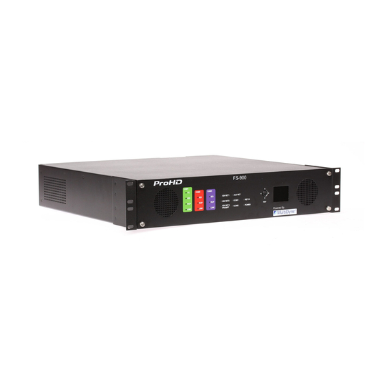
Application & Usage ProHD Base Unit All of the video signals coming from the camera and its accessories (viewfinder, etc.) are fed to the FS-900 Tri- ple Studio Camera Interface system’s 1RU base station enclosure via the SMPTE or opticalCON swivel connec- tor,that also supplies power. -
Page 10: Signal Flow: Base Unit
Signal Flow: Base Unit Signal Flow: Camera Head... -
Page 11: Operation: Base Unit Operational Description
Operation: Base Unit Operational Description Operation Home Status Screen: Base Fiber Status Menu: Fiber Status System Status Base Fiber Status A/V Status Base Top Menu Base: Cam1 Cam2 Cam3 Camera1: Rx1: -xxdBm -xxdBm -xxdBm System Status Camera2: Rx2: -xxdBm -xxdBm -xxdBm Camera3: Rx3: -xxdBm -xxdBm -xxdBm... -
Page 12: Operation
Operation Operation Camera 1 Top Menu: Camera 1 System Status Menu: Camera 2 A/V Status Menu: Camera 3 Fiber Status Menu Camera 1 Menu Cam1 System Status Cam2 Video Status Cam3 Fiber Status Rx Pwr Temp Fiber Status CPU Rev: Cam1: SD/HD/3G -xxdBm... -
Page 13: Technical Specifications
Camera Remote Control Impedance 75 Ohms Level 1Vp-p RCP Camera Control (Remote) Connector, Camera Unit Internal 68-pin Type JVC RCP (RS232) Connector, Base Unit Connector, Camera Unit Internal 68-pin Connector, Base Unit Connector, Base Unit 6 pin Mini-DIN Embedded Audio Supported Ethernet... - Page 14 Technical Specifications Detail Connector Pinouts Base Unit Intercom/Audio Connector Pinout Electro-Optical Operating Wavelengths 1471-1611nm Number Description Number Description TX Laser Output Power 0dBm (Class 1 Laser) 2-Wire Intercom Pin2 / 4-Wire 2-Wire Intercom Pin3 / 4-Wire Intercom Ch1 Output+ Intercom Ch2 Output+ Receiver Sensitivity -20dBm 4-Wire Intercom Ch1 Output-...
-
Page 15: Detail Connector Pinouts
Detail Connector Pinouts Camera Unit GPIO Connector Pinout Number Description Number Description Program (Red) Tally GPO Output Preview (Green) Tally GPO Output GPO Output Intercom MIC Ch1 PTT GPI Input GPI Input Intercom MIC Ch2 PTT GPI Input Viewfinder Input Select GPI Input +12VDC Output Camera Unit Audio Connector Pinout... -
Page 16: Newton Place Hauppauge, Ny
110 Newton Place Hauppauge, NY 11788 (800)-488-8378 / (516)-671-7278 sales@multidyne.com www.multidyne.com ©2016 MultiDyne, Inc MDDOC00170.RevA November, 2016...
Need help?
Do you have a question about the FS-900 and is the answer not in the manual?
Questions and answers