Table of Contents
Advertisement
Quick Links
Download this manual
See also:
Instruction Manual
STUDIO VIEWFINDER
VF-HP790G
Thank you for purchasing this JVC product.
Before beginning to operate this unit, please read
the instructions carefully to ensure the best
possible performance.
For Customer Use:
Enter below the Serial No. which is located on the
body.
Retain this information for future reference.
VF-HP790G
Model No.
Serial No.
INSTRUCTIONS
LST1110-001A
Advertisement
Table of Contents

Related Manuals for JVC VF-HP790G


Summary of Contents for JVC VF-HP790G
- Page 1 STUDIO VIEWFINDER VF-HP790G INSTRUCTIONS Thank you for purchasing this JVC product. Before beginning to operate this unit, please read the instructions carefully to ensure the best possible performance. For Customer Use: Enter below the Serial No. which is located on the body.
-
Page 2: Important Safeguards
Introduction FOR USA These are general IMPORTANT SAFEGUARDS and certain items may not apply to all appliances. IMPORTANT SAFEGUARDS Read all of these instructions. Save these instructions for later use. All warnings on the product and in the operating instructions should be adhered to. Unplug this appliance system from the wall outlet before cleaning. -
Page 3: Safety Precautions
D’ELECTROCUTION, NE PAS EXPOSER L’APPAREIL A CAUTION: L’HUMIDITE OU A LA PLUIE. CHANGES OR MODIFICAT IONS NOT APPROVED BY JVC ATTENTION: COULD VOID USER’S AUTHORITY TO OPERATE THE Ce magnétoscope ne doit être utilisé que sur du courant direct en 12V. - Page 4 (Business users) If you wish to dispose of this product, please visit our web Dear Customer, page http://www.jvc.eu to obtain information about the take- This apparatus is in conformance with the valid European directives and back of the product. standards regarding electromagnetic compatibility and electrical safety.
-
Page 5: Table Of Contents
Specifications ........14 ● All rights reserved by JVC. Unauthorized duplication or reprinting of this manual, in whole or in part, is strictly prohibited. -
Page 6: Precautions During Use
Introduction Precautions During Use Energy Conservation When this product is not used for a prolonged period of time, turn off the power of the system for safety and energy conservation purposes. Location of Storage and Use LCD Screen Do not place this product at the following locations. Leaving the LCD screen exposed to the sun will damage the Doing so may cause the product to malfunction or break LCD screen. -
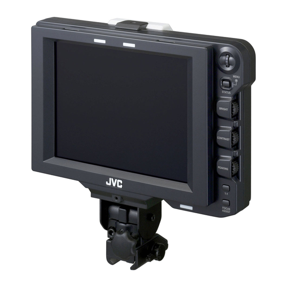
Page 7: Names Of Parts And Functions (Front)
[BRIGHT] Adjustment Control Names of Parts and For adjusting the brightness of the screen. Turn to the right to brighten and to the left to darken. Functions (Front) Memo : ● When the camera’s viewfinder image is input, the [VF BRIGHT] adjustment knob on the camera is disabled. -
Page 8: Names Of Parts And Functions (Rear)
Introduction [SDI INPUT] Terminal Names of Parts and The input terminal for SDI video signals. To display the image from this terminal, set [INPUT SOURCE] Functions (Rear) in the [VIDEO FORMAT] menu to ASDIB. (A Page 11) To use the image from this terminal as return signals, set [SDI RETURN] to AONB while [INPUT SOURCE] is being set to AVFB. -
Page 9: Setup
Setup Installation Connecting VF Cable Before connecting the VF cable, be sure to turn off the POWER switch on the camera or on the remote control unit. Connect the viewfinder’s [VF CABLE] terminal to the [VF] terminal of the GY-HM790 series with the provided VF cable. Mounting on KA-790G VF Cable Rotate the lock lever in the arrow direction ( ) -
Page 10: Mounting The Hood Cover (Provided)
Setup Installation (continued) Displaying the Images Set the POWER switch on remote control unit or camera to AONB, to display the image on the Mounting the Hood Cover (Provided) viewfinder. Align the hood cover with the groove on top of Memo :... -
Page 11: Menu
Menu Setting the Menu Entering the Camera Name Display the [OTHERS] menu screen. O T H E R S [MENU] Dial C AME RA N AME MENU [STATUS/MENU] N AME E D I T H P 7 9 0 G STATUS Button B L A C K &WH I T E... -
Page 12: Menu Screen
Menu Menu Screen The Menu screen consists of the following structure as shown below. M A I N M E NU - - MA R K E R S E T T I NG MA R K ER S E T T I NG . . A S P E C T T Y P E V I D EO S HOO T I NG A S S I S T . -
Page 13: Marker Setting Menu Screen
MARKER SETTING Menu Screen Settings in bold are factory default settings. Memo : ● The [MARKER SETTING] menu is valid for the image from this viewfinder’s [SDI INPUT] terminal. When [INPUT SOURCE] in the [VIDEO FORMAT] menu is set to AVFB, all items in the [MARKER SETTING] menu appear as A----B and cannot be selected. -
Page 14: Shooting Assist Menu Screen
Menu Menu Screen (continued) SHOOTING ASSIST Menu Screen Settings in bold are factory default settings. Item Setting Value Description FOCUS ASSIST This item sets the display color of the focus section when the FOCUS ASSIST function is operated. GREEN This item is enabled when [INPUT SOURCE] in the [VIDEO FORMAT] menu is set to BLUE ASDIB. -
Page 15: Video Format Menu Screen
Item Setting Value Description PEAKING FREQ. This item sets the frequency band where the contour is emphasized with the MIDDLE [PEAKING] control. : Emphasizes the low frequency band. HIGH MIDDLE : Emphasizes the intermediate frequency band. HIGH : Emphasizes the high frequency band. Memo :... -
Page 16: Others Menu Screen
EXECUTE : Executes Menu Reset. PAGE BACK This returns to the [MAIN MENU] screen. Precautions when Using with the GY-HM790 Series Items with restricted operation at VF-HP790G depending on camera settings Setting Item Setting Value Restricted Operation Tally System Studio The TALLY lamp displays TALLY(PGM/PVM), CALL and warning from the remote control. -
Page 17: Others
Others Terminal Specifications VF Terminal 20-pin Connector Pin No. Name IN/OUT GND0 12 V SCL (D3-) CLK+ CLK- GNDC SDA (D3+) GND 1 VF_SEN (GND3) GND2 NRESET IN/OUT VF_D_IN DC INPUT Terminal 4-pin Connector Pin No. Name IN/OUT +12 V [VF CABLE] Connector [DC INPUT] Connector 13 14 15... -
Page 18: Troubleshooting
Others Troubleshooting Troubleshooting Check Point Power does not turn on Insert the VF cable or power cable fully. Turn on the power supply of the GY-HM790 series/RM-HP250. There are no images Insert the VF cable fully. Turn on the power supply of the GY-HM790 series/RM-HP250 and set the correct settings. - Page 19 Dimensional Outline Drawing (Unit: mm) Without Hood With Hood MENU STATUS BRIGHT CONTRAST PEAKING FOCUS ASSIST * The specifications and appearance of this product and other related products may be modified for improvement without prior notice.
- Page 20 © 2010 Victor Company of Japan, Limited LST1110-001A...
Need help?
Do you have a question about the VF-HP790G and is the answer not in the manual?
Questions and answers