Table of Contents
Advertisement
Quick Links
OPERATIONS MANUAL
.
Prepared for:
Date:
Rev:
Due to design changes and device availability, the information and data presented in this
for a
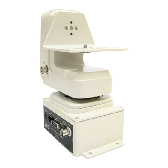
JVC
Pan/Tilt Head
JVC Professional Products Company
1700 Valley Road
Wayne, NJ 07470
Document No. D0153
10 June 2002
-
manual are subject to possible change without prior notice.
Advertisement
Table of Contents

Related Manuals for JVC DPT 115


Summary of Contents for JVC DPT 115
- Page 1 Rev: Due to design changes and device availability, the information and data presented in this manual are subject to possible change without prior notice. for a JVC Professional Products Company 1700 Valley Road Wayne, NJ 07470 Document No. D0153 10 June 2002...
-
Page 2: Table Of Contents
... 12 NDICATORS 4.2.1 Power Indicator-Green LED 4.2.2 Data Indicator-Red LED CONNECTOR INFORMATION ... 13 ONNECTOR ANEL 5.1.1 Lens I/F Connector: NOT USED JVC Configuration 5.1.2 Communications Interface 5.1.3 RS-422 Connector... 14 5.1.4 RS-232 Connector... 15 5.1.5 +15 VDC Power Jack ... - Page 3 Lens I/F Connector ... 29 Lens Control Cable Installation... 29 6.9.8.1 KY-F32 Configuration...29 KY-F55 Configuration...30 DPT 115 LDCC Cable Installation (Used with LDCC Option Only) 7. TROUBLE SHOOTING ... 31 & T ... 31 ... 31 ONTROL LDCC ... 31 ...
-
Page 4: Introduction
Teleconferencing and CCTV lenses may all be easily interfaced to the versatile DPT 115. Presets are available on the DPT 115 for pan, tilt, zoom and focus. The resolution of the presets is 12 bits giving an angular resolution of 0.1 degree. Setup switches located at the base of the unit make special functions and configuration changes easily implemented. -
Page 5: Pan & Tilt Head Specifications
PAN & TILT HEAD SPECIFICATIONS: HARACTERISTICS Operating Environment ...Indoor Temperature...40 to 104 degrees F. (0 to 40 degrees C.) Pan Rotation ...260 degrees with adjustable limit switches Tilt Angle ...+/- 45 degrees with adjustable limit switches Pan Speed ...Continuously variable to 15 degrees/second Tilt Speed ...Continuously variable to 7.5 degrees/second Load Mounting...Side loading with alignment of image plane Capacity ...8 pounds... - Page 6 ONNECTORS RS-422 Serial Interface ...4 conductor RJ-11 style RS-232 Serial Interface ...9 pin D connector Power ...DC Jack Pass through ...8 pin mini- DIN lens pass through connector Video ...BNC 2/12/05 Document D0153...
-
Page 7: Rs-422
Functions of the pan and tilt include manual camera positioning, manual zoom and focus control, and presets. Presets are stored pan, tilt, zoom, and focus positions that the DPT 115 will return to automatically when recalled. The preset data is stored within the pan and tilt head. This data is stored and recalled from the controller or computer system. -
Page 8: Pan & Tilt Limit Adjustment
3.3.2 Pan & Tilt Limit Adjustment The pan & tilt head has separate adjustments for limiting pan-left, pan-right, tilt-up and tilt- down. The adjustment of these limits are described below. NOTE: These adjustments are to be made after the controller has been interfaced to the DPT 115. -
Page 9: Tilt Adjustment
Tilt Adjustment View B illustrates the location of the Tilt Up and Tilt Down Limit Adjustments. With the camera mounted on the pan & tilt as shown in Figure 3, turn the system power “ON” and move the JOYSTICK up until the rear of the camera nears the bottom of the pan & tilt. Make sure the camera does not hit the pan &... -
Page 10: Switch Panel, Controls And Indicators
SWITCH PANEL, CONTROLS AND INDICATORS CONTROLS 4.1.1 Power Switch A main power switch is provided at the switch panel of the pan and tilt head. When closed this small slide switch provides DC voltage from the pan and tilt power supply to the electronics located within the base of the head. - Page 11 Setup Switches located on the base of the DPT 115 The Function of each of these switches is as follows: 8, Pan & Tilt Only • Up: Pan, Tilt, Zoom and Focus Presets are enabled • Down: Only Pan & Tilt Presets are allowed 7, Teleconferencing Lens •...
-
Page 12: Indicators
INDICATORS 4.2.1 Power Indicator-Green LED The Power LED is located adjacent to the power switch on the pan and tilt switch panel. When the “POWER” LED is illuminated, the power switch is closed and power is applied to the pan and tilt head control electronics. -
Page 13: Connector Information
The connector labeled “LENS I/F” on the connector plate is an eight mini DIN female (socket) type. This connector provides signals to and from the camera lens in special applications. Internal wiring for this connector can be found on the MPU Module schematic diagram and is directly wired to the 8 pin DIN connector located on the body of the pan &... -
Page 14: Communications Interface
The RS-422 communications interface is also used to pass camera control commands to the camera in the camera control mode (LDCC) for JVC cameras. In this mode the controller sends the camera commands to the head in RS-422 format on the four wire cable. The commands are received in RS-422 and converted to TTL levels by electronics in the head. -
Page 15: Rs-232 Connector
5.1.4 RS-232 Connector The connector labeled “RS232” on the connector plate is a nine pin sub-miniature female (socket) “D” type. This connector provides data for either the LDCC option or a RS-232 computer interface to the digital pan and tilt head. The pin numbers for the RS-232 connector are clearly labeled on the connector. -
Page 16: Vdc Power Jack
This connector which is located on the trunnion adjacent to the video BNC connector provides a means to connect the camera lens control signals from the pan and tilt head to the camera/lens assembly. The output pin assignments for this connector are jumper selectable from within the pan and tilt base. - Page 17 The pin assignments schemes for teleconferencing lenses with preset capabilities are shown in the table below: DIN Connector 2/12/05 Teleconferencing * Focus Zoom Auto/Manual Iris Iris Zoom Select +5VDC (Lens Sense) Ground Document D0153...
-
Page 18: Dpt Jumper Installation
DPT JUMPER INSTALLATION. It will be necessary to disassemble pan and tilt mechanism from base of DPT unit to gain access to the configuration jumpers on the MPU PWA. The MPU PWA is the top board and will be accessible as soon as the pan and tilt mechanism is removed. The following steps describe reconfiguring the jumpers. -
Page 19: Installation
INSTALLATION TOOLS AND EQUIPMENT NEEDED • Screwdriver and Mounting Screws: The only tool needed to install the DPT 115 is a screwdriver for securing the pan & tilt base to its mount. • #2 Phillips Screwdriver: To be used if access into the Electronics module is required. - Page 20 BALANCE POINT OF CAMERA & LENS OVER CENTER OF P/T JVC 3-CCD 2/12/05 Document D0153...
-
Page 21: Dpt 115 Footprint Drawing
DPT 115 FOOTPRINT DRAWING The required hole pattern for securing the pan & tilt head to a mounting surface is a symmetrical two-inch by five-inch pattern. Four (4) mounting screws are needed to mount the pan & tilt head. Care is to be taken to mount the pan & tilt in the proper orientation. Note the location of the connector plate on the base of the pan &... -
Page 22: Mounting Teleconferencing Lens Adapter
Using this bracket allows the camera and lens assembly to be mounted on the pan and tilt with the balance point of the weight centrally aligned to the tilt pivot point of the pan and tilt head. JVC KY-F32 Camera & Lens 3-CCD Teleconferencing Lens Adapter... -
Page 23: Camera And Len
BALANCING CAMERA AND LENS 1. Place the camera/lens/adapter plate on a flat surface. Place a pencil or other small round cylindrical item under the teleconferencing lens adapter plate as shown. 2. Move the camera/lens/adapter plate laterally, both left and right to determine the balance point of the assembly. - Page 24 5. Place the camera/lens/adapter plate on the pan and tilt as shown below. Position camera/lens/adapter plate assembly such that balance point is located directly over center point of the tilt axis of the pan and tilt head. Install mounting screw and washers at this time, Do not tighten.
-
Page 25: Inverted Installation
6.6 INVERTED INSTALLATION The pan and tilt unit may be inverted or hung in certain applications. The teleconferencing lens adapter bracket is required to provide the necessary clearance between the lens and the side of the pan and tilt. If the unit is hung the pan left, pan right, tilt up, and tilt down functions will be backwards for that particular camera station. -
Page 26: Wall Mount Installation
WALL MOUNT INSTALLATION 3-CCD 4, # 10 FLAT HEADSCREWS WITH SELF LOCKING NUTS TRIPOD ADAPTER PLATE ¼-20 SCREW LARGE FLAT LOCK 2/12/05 Document D0153... -
Page 27: Tripod Installation
TRIPOD INSTALLATION 2/12/05 Document D0153... -
Page 28: Cabling
CABLING 6.9.1 Attach Video Cable, User Equipment Attach the user’s video cable to BNC on the pan and tilt base. This cable provides the video interface to the customer equipment from the pan and tilt/camera/lens assembly. This user provided cable is to be connected between the “VIDEO IN” connector on the customers equipment and the BNC “VIDEO”... -
Page 29: Rs-232 Cable Installation
6.9.5 RS-232 Cable Installation. The RS-232 cable provides the control interface between the DPT 115 pan and tilt head and the controller if an RS-232 interface is desired. Figure 3-3 illustrates a typical RS-232 cable. Black Black White Connect the plug (male) end of RS-232 to the nine pin “D” connector on the pan and tilt head. -
Page 30: Ky-F55 Configuration
DPT 115 LDCC Cable Installation (Used with LDCC Option Only) Attach the 9-pin Dsub male connector of the DPT 115 LDCC cable (ACA96052200) to the “RS232” connector on the base of the pan and tilt. Connect other end, 6-pin male mini-DIN to “REMOTE”... -
Page 31: Trouble Shooting
7. TROUBLE SHOOTING PAN & TILT Problem: No pan/tilt or lens functions. Verify proper power is supplied to head. Verify data is being sent to head. LENS CONTROL Problem: No zoom or focus. Verify lens control cable is plugged in pan and tilt head. Verify lens control cable is plugged into correct Hirose cable on lens. -
Page 32: Presets
PRESETS Problem: Camera does not return to preset locations consistently. Verify camera and lens are balanced properly. Verify cable assemblies do not restrict camera and lens movement. Problem: Red LED does not extinguish when going to a reset. Verify camera and lens are balanced properly. TECHNICAL SUPPORT For technical assistance call (321) 956-0095 or go to web site at esi-inc.com. -
Page 33: Cable Drawings
CABLE DRAWINGS LENS CABLE DRAWING ACL99088000 FOCUS + (Near Command) ZOOM + (Wide Command) Auto Iris IRIS Zoom Select + 5 VDC(Lens Sense) (POT-) GND & TILT 2/12/05 CONNECTOR JACK Yellow Gray Orange Blue Green Black 7.5 VDC Focus Select LENS REMOTE CONTROL... -
Page 34: Pan & Tilt Ldcc Cable Drawing
PAN & TILT LDCC CABLE DRAWING ACA96052200 1 2 3 4 5 6 7 8 9 9 Pin Male "D" (Plug) 2/12/05 SID1 (Data to Camera) *Operate(To Camera) Ground Ground SID2 (Data from Camera) View From Mating Connector 6 Pin Male Mini-DIN(Plug) Document D0153... -
Page 35: Rs-422 Cable
RS-232 CABLE DRAWING 9 Pin Female (Model 80) 2/12/05 P/T Tx - Black P/T Tx + P/T Rx - Green P/T Rx + Yellow ACA96037900 ACA96041600 DATA FROM DPT 115 DATA TO DPT 115 9 Pin Male (DPT 115) Document D0153... -
Page 36: Serial Command List
9. SERIAL COMMAND LIST Commands or Actions used to control the DPT 115 Digital Pan & Tilt Head. Command Joystick Down Left Right Focus Near Zoom Wide (Speed) Wide (Position) Telephoto (Speed) Telephoto (Position) Iris Open Close Auto Auxiliary Rotate Right... -
Page 37: Glossary
Teleconferencing Lens: A lens in which the zoom and focus control electronics are located within the lens. The DPT 115 supplies a single wire interface to each of the zoom and focus electronic inputs.
Need help?
Do you have a question about the DPT 115 and is the answer not in the manual?
Questions and answers