
Related Manuals for AirLive IGR-842PoE


Summary of Contents for AirLive IGR-842PoE
- Page 1 IGR-842PoE 6 port Gigabit PoE with 2 port SFP industrial ring manage switch Web User Manual...
- Page 2 OvisLink Corp. has made the best effort to ensure the accuracy of the information in this user’s guide. However, we are not liable for the inaccuracies or errors in this guide. Please use with caution. All information is subject to change without notice All Trademarks are properties of their respective holders. AirLive IGR-842PoE User Manual...
-
Page 3: Table Of Contents
3.1 Important Information ................ 11 3.2 Prepare your PC ................11 3.3 Management Interface ..............11 3.4 Introduction to Web Management ............ 12 4. Web Management: Configuration of IGR-842POE ......15 4.1 System .................... 15 4.2 Green Ethernet ................28 4.3 Port ....................30 4.4 DHCP .................... - Page 4 4.19 QoS ....................170 4.20 Mirroring ..................192 4.21 GVRP ...................193 4.22 sFlow ....................194 4.23 RingV2 ..................197 4.24 DDMI ....................199 5. Web Management: Monitor of IGR-842POE ........200 5.1 Sysytem ..................200 5.2 Green Ethernet ................205 5.3 Ports ....................206 5.4 DHCP .....................212 5.5 Security ..................219 5.6 LACP ....................238...
- Page 5 Table of Contents 5.17 RingV2 ..................271 5.18 DDMI ....................272 6. Web Management: Diagnostics of IGR-842POE .......275 6.1 Ping ....................275 6.2 Ping6 ....................276 6.3 VeriPHY ..................277 7. Web Management: Maintenance of IGR-842POE ......279 7.1 Restart Device ................279 7.2 Factory Default ................279 7.3 Software ..................280...
-
Page 6: Introduction
Introduction 1.1 Overview The IGR-842POE is a 6 port Gigabit with 2-Port Gigabit TP/SFP slots Ring industrial switch. With robust design and wide working temperature from -40 degree to 70 degree , The IGR-842POE is able to work in any demanding environment such as factory or intersection. -
Page 7: How To Use This Guide
1. Introduction IGR-842POE is also a PoE switch which can power on any PoE client such as IP cameras , VoIP phone. Note: If the switch is used in outdoor environment or connect with cable to outdoor , it is suggested to add a lightning arrester to protect the switch.. -
Page 8: Installing The Igr-842Poe
Do not create a network loop. Always check the LED lights for troubleshooting 2.2 Package Content Unpack the contents of the IGR-842POE Plus and verify them against the checklist below. One unit of IGR-842POE Quick Installation Guide ... -
Page 9: Optional Accessory
2. Installing the IGR-842POE Compare the contents of your IGR-842POE package with the standard checklist above. If any item is missing or damaged, please contact your local dealer for service. 2.3 Optional Accessory The IGR-842POE has the following optional accessories which you can purchase from AirLive ... -
Page 10: Knowing Your Igr-842Poe
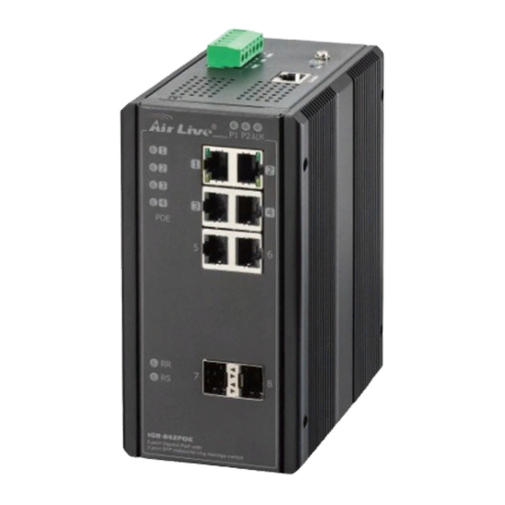
2. Installing the IGR-842POE Note: While installing MiniGBIC into SFP slot of IGR-842POE, please notice the direction of MiniGBIC is correct, and make sure that MiniGBIC is indeed installed in the IGR-842POE. 2.4 Knowing your IGR-842POE Below are descriptions and diagrams of the product:... -
Page 11: Hardware Installation
2. Installing the IGR-842POE 2.5 Hardware Installation Set the IGR-842POE on a sufficiently large flat space with a power outlet nearby. The surface where you put your IGR-842POE should be clean, smooth, level and sturdy. Make sure there is enough clearance around the IGR-842POE to allow attachment of cables, power cord and allow air circulation. - Page 12 Screw the din-clip with screws in the accessory kit. Hook the unit onto the din-rail. Push the bottom of the unit towards the din-rail until it locks in place. 2.5.3. Ground Connection IGR-842POE must be properly grounded for optimum system performance. AirLive IGR-842POE User Manual...
- Page 13 The DC power interface is a 6-pin terminal block with polarity signs on the top panel. The IGR-842POE can be powered from two power supply (input range 12V – 58V). The DC power connector is a 6-pin terminal block; There is alarm contact on the middle terminal block.
-
Page 14: Led Table
2. Installing the IGR-842POE 2.6 LED Table The LED Indicators gives real-time information of systematic operation status. The following table provides descriptions of LED status and their meaning. Status Description Green P1 power line has power P1 power line disconnect or does not have... - Page 15 2. Installing the IGR-842POE A 100 Mbps or a 1000Mbps connection is Yellow Copper ports Speed detected No link or a 10 Mbps connection is detected Green Ethernet link up SFP port Link/Act Ethernet link down SFP port speed 1000Mbps connection is Yellow detected.
-
Page 16: Introduce The Igr-842Poe
The default PoE mode is “Disable” 3.2 Prepare your PC The IGR-842POE can be managed remotely by a PC through RJ-45 cable. The default IP address of the IGR-842POE is 192.168.2.1 with a subnet mask of 255.255.255.0. This means the IP address of the PC should be in the range of 192.168.2.2 to 192.168.2.253. -
Page 17: Introduction To Web Management
Web Management (HTTP): You can manage your IGR-842POE by simply typing its IP address in the web browser. Most functions of IGR-842POE can be accessed by web management inter face. We recommend using this interface for initial configurations. To begin, simply enter IGR-842POE’s IP address (default is 192.168.2.1) on the web browser. - Page 18 3. Introduce the IGR-842POE 3.4.2. Menu Structure of IGR-842POE The web management menu of IGR-842POE is divided into 3 parts: Top Bar, Side Menu Top Bar Bar, and Main Screen. Side Menu Main Screen Top Bar: It display panel GUI. You can direct click the port on the Switch figure on the top of web page.
- Page 19 3. Introduce the IGR-842POE Side Menu: All management functions will show in Side Menu, you can choose any one of them to configure its setting. The detailed introduction for all management function will explain in below chapters. The following list is the full function tree for web user interface.
-
Page 20: Web Management: Configuration Of Igr-842Poe
5. Web Management: Monitor of IGR-842POE Web Management: Configuration of IGR-842POE 4.1 System This chapter describes the entire basic configuration tasks which includes the System Information and any manage of the Switch (e.g. Time, Account, IP, Syslog and NTP.) Please Click Maintenance, Configuration and Save starup-config to save the configuration. - Page 21 Save - Click to save changes. Reset - Click to revert to previously saved values. 4.1.2. System IP This sector is to provide and config the IP information of the IGR-842POE. Web Interface To configure an IP address in the web interface: 1.
- Page 22 5. Web Management: Monitor of IGR-842POE Parameter description: IP Configuration Mode Configure whether the IP stack should act as a Host or a Router : Host mode IP traffic between interfaces will not be routed Router traffic is routed between all interfaces.
- Page 23 5. Web Management: Monitor of IGR-842POE From this DHCP interface Specify from which DHCP-enabled interface a provided DNS server should be preferred DNS Proxy When DNS proxy is enabled, system will relay DNS requests to the currently configured DNS server, and reply as a DNS resolver to the client devices on the network.
- Page 24 5. Web Management: Monitor of IGR-842POE IPv4 Mask The IPv4 network mask, in number of bits (prefix length). Valid values are between 0 and 30 bits for a IPv4 address. If DHCP is enabled, this field is not used. The field may also be left blank if IPv4 operation on the interface is not desired.
- Page 25 5. Web Management: Monitor of IGR-842POE Gateway The IP address of the IP gateway. Valid format is dotted decimal notationor a valid IPv6 notation. Gateway and Network must be of the same type. Next Hop VLAN (Only for IPv6) The VLAN ID (VID) of the specific IPv6 interface associated with the gateway.
- Page 26 5. Web Management: Monitor of IGR-842POE 3. Click Save. Parameter description: Mode: Indicates the NTP mode operation. Possible modes are: Enabled: Enable NTP client mode operation. Disabled: Disable NTP client mode operation. Server #: Provide the IPv4 or IPv6 address of a NTP server. IPv6 address is in 128-bit records represented as eight fields of up to four hexadecimal digits with a colon separating each field (:).
- Page 27 5. Web Management: Monitor of IGR-842POE Web Interface To configure log configuration in the web interface: 1. Click Configuration, System Time 2. Specify the Time parameter. 3. Click Save. AirLive IGR-842POE User Manual...
- Page 28 5. Web Management: Monitor of IGR-842POE Parameter description: Time Zone Configuration Time Zone Lists various Time Zones worldwide. Select appropriate Time Zone from the drop down and click Save to set Acronym : User can set the acronym of the time zone. This is a User configurable acronym to identify the time zone.
- Page 29 5. Web Management: Monitor of IGR-842POE Month - Select the starting month. Hours - Select the starting hour Minutes - . Select the starting minute End time settings Week - Select the ending week number. ...
- Page 30 5. Web Management: Monitor of IGR-842POE Month - Month of current datetime. Date - Date of current datetime. Hours - Hour of current datetime. Minutes - Minute of current datetime. Seconds - Second of current datetime.
- Page 31 5. Web Management: Monitor of IGR-842POE UDP communication and received on UDP port 514 and the syslog server will not send acknowledgments back sender since UDP is a connectionless protocol and it does not provide acknowledgments. The syslog packet will always send out even if the syslog server does not exist.
- Page 32 5. Web Management: Monitor of IGR-842POE Parameter description: The identification of the Alarm Profile entry. Description Alarm Type Description. Enabled If alarm entry is Enabled, then alarm will be shown in alarm history/current when it occurs. Alarm LED will be on (lighted), Alarm Relay also be enabled.
-
Page 33: Green Ethernet
5. Web Management: Monitor of IGR-842POE Buttons Save – Click to save changes. Reset - Click to undo any changes made locally and revert to previously saved values. Note: When any alarm exists, the Alarm LED will be on (lighted), Alarm Output Relay will also be enabled. - Page 34 5. Web Management: Monitor of IGR-842POE Parameter description: Port Power Saving Configuration Optimize EEE for The switch can be set to optimize EEE for either best power saving or least traffic latency. Port Configuration Port The switch port number of the logical port.
-
Page 35: Port
5. Web Management: Monitor of IGR-842POE For maximizing power savings, the circuit isn't started at once transmit data is ready for a port, but is instead queued until a burst of data is ready to be transmitted. This will give some traffic latency. - Page 36 5. Web Management: Monitor of IGR-842POE Parameter description: Port : This is the logical port number for this row. Link : The current link state is displayed graphically. Green indicates the link is up and red that it is down.
-
Page 37: Dhcp
5. Web Management: Monitor of IGR-842POE Check the configured column to use flow control. This setting is related to the setting for Configured Link Speed. Maximum Frame Size : Enter the maximum frame size allowed for the switch port, including FCS. - Page 38 5. Web Management: Monitor of IGR-842POE Parameter description: Global VLAN Mode : Configure the operation mode per system. Possible modes are: Enabled: Enable DHCP server per system. Disabled: Disable DHCP server pre system. VLAN Mode VLAN Range : Indicate the VLAN range in which DHCP server is enabled or disabled. The first VLAN ID must be smaller than or equal to the second VLAN ID.
- Page 39 5. Web Management: Monitor of IGR-842POE Mode : Indicate the the operation mode per VLAN. Possible modes are: Enabled: Enable DHCP server per VLAN. Disabled: Disable DHCP server pre VLAN. Buttons Delete - Click to delete the setting. Add VLAN Range - Click to add a new VLAN range.
- Page 40 5. Web Management: Monitor of IGR-842POE IP Range : Define the IP range to be excluded IP addresses. The first excluded IP must be smaller than or equal to the second excluded IP. BUT, if the IP range contains only 1 excluded IP, then you can just input it to either one of the first and second excluded IP or both.
- Page 41 5. Web Management: Monitor of IGR-842POE Type : Display which type of the pool is. Network: the pool defines a pool of IP addresses to service more than one DHCP client. Host: the pool services for a specific DHCP client identified by client identifier or hardware address.
- Page 42 5. Web Management: Monitor of IGR-842POE 3. Select “Trusted” of the specific port in the Mode of Port Mode Configuration. 4. Click Save. Parameter description: Snooping Mode : Indicates the DHCP snooping mode operation. Possible modes are: Enabled: Enable DHCP snooping mode operation. When DHCP snooping mode...
- Page 43 5. Web Management: Monitor of IGR-842POE Buttons Save – Click to save changes. Reset - Click to undo any changes made locally and revert to previously saved values. 4.4.3. DHCP Relay A DHCP relay agent is used to forward and to transfer DHCP messages between the clients and the server when they are not in the same subnet domain.
-
Page 44: Security
5. Web Management: Monitor of IGR-842POE Relay Information Mode : Indicates the DHCP relay information mode option operation. The option 82 circuit ID format as "[vlan_id][module_id][port_no]". The first four characters represent the VLAN ID, the fifth and sixth characters are the module ID(in standalone device it always equal 0, in stackable device it means switch ID), and the last two characters are the port number. - Page 45 5. Web Management: Monitor of IGR-842POE 4.5.1.1. User This page provides an overview of the current users. Currently the only way to login as another user on the web server is to close and reopen the browser. Web Interface To monitor an Security User in the web interface:...
- Page 46 5. Web Management: Monitor of IGR-842POE Privilege Level The privilege level of the user. The allowed range is 1 to 15. If the privilege level value is 15, it can access all groups, i.e. that is granted the fully control of the device.
- Page 47 5. Web Management: Monitor of IGR-842POE Parameter description: Group Name : The name identifying the privilege group. In most cases, a privilege level group AirLive IGR-842POE User Manual...
- Page 48 5. Web Management: Monitor of IGR-842POE consists of a single module (e.g. LACP, RSTP or QoS), but a few of them contains more than one. The following description defines these privilege level groups in details: System: Contact, Name, Location, Timezone, Daylight Saving Time, Log.
- Page 49 5. Web Management: Monitor of IGR-842POE Parameter description: Client : The management client for which the configuration below applies. Methods : Method can be set to one of the following values: no: Authentication is disabled and login is not possible.
- Page 50 5. Web Management: Monitor of IGR-842POE Enable SSH Configuration Click Save Parameter description: Mode : Indicates the SSH mode operation. Possible modes are: Enabled: Enable SSH mode operation. Disabled: Disable SSH mode operation. Buttons Save – Click to save changes.
- Page 51 5. Web Management: Monitor of IGR-842POE Parameter description: Mode : Indicates the SSH mode operation. Possible modes are: Indicates the HTTPS mode operation. When the current connection is HTTPS, to apply HTTPS disabled mode operation will automatically redirect web browser to an HTTP connection. Possible modes are: Enabled: Enable HTTPS mode operation.
- Page 52 5. Web Management: Monitor of IGR-842POE Parameter description: Mode : Indicates the access management mode operation. Possible modes are: Enabled: Enable access management mode operation. Disabled: Disable access management mode operation. Delete : Check to delete the entry. It will be deleted during the next save VLAN ID : Indicates the VLAN ID for the access management entry.
- Page 53 5. Web Management: Monitor of IGR-842POE 4.5.1.7. SNMP Any Network Management System (NMS) running the Simple Network Management Protocol (SNMP) can manage the Managed devices equipped with SNMP agent, provided that the Management Information Base (MIB) is installed correctly on the managed devices.
- Page 54 5. Web Management: Monitor of IGR-842POE Mode : Indicates the SNMP mode operation. Possible modes are: Enabled: Enable SNMP mode operation. Disabled: Disable SNMP mode operation. Version : Indicates the SNMP supported version. Possible versions are: SNMP v1: Set SNMP supported version 1.
- Page 55 5. Web Management: Monitor of IGR-842POE Click Configuration, SNMP and Trap Click Add New Entry then you can create new SNMP Trap on the switch Click Save Parameter description: Global Setting Mode : Indicates the trap mode operation. Possible modes are: Enabled: Enable SNMP trap mode operation.
- Page 56 5. Web Management: Monitor of IGR-842POE Disabled: Disable SNMP trap mode operation. Trap Destination Configurations Name: Indicates the trap Configuration's name. Indicates the trap destination's name. Enable : Indicates the trap destination mode operation. Possible modes are: Enabled: Enable SNMP trap mode operation.
- Page 57 5. Web Management: Monitor of IGR-842POE Trap Community : Indicates the community access string when sending SNMP trap packet. The allowed string length is 0 to 255, and the allowed content is ASCII characters from 33 to 126. Trap Destination Address : Indicates the SNMP trap destination address.
- Page 58 5. Web Management: Monitor of IGR-842POE 16. Trap Probe Security Engine ID : Indicates the SNMP trap probe security engine ID mode of operation. Possible values are: Enabled: Enable SNMP trap probe security engine ID mode of operation. Disabled: Disable SNMP trap probe security engine ID mode of operation.
- Page 59 5. Web Management: Monitor of IGR-842POE Check to delete the entry. It will be deleted during the next save. Community : Indicates the community access string to permit access to SNMPv3 agent. The allowed string length is 1 to 32, and the allowed content is ASCII characters from 33 to 126.
- Page 60 5. Web Management: Monitor of IGR-842POE Engine ID : An octet string identifying the engine ID that this entry should belong to. The string must contain an even number(in hexadecimal format) with number of digits between 10 and 64, but all-zeros and all-'F's are not allowed. The SNMPv3...
- Page 61 5. Web Management: Monitor of IGR-842POE AES: An optional flag to indicate that this user uses AES authentication protocol. Privacy Password : A string identifying the privacy password phrase. The allowed string length is 8 to 32 and the allowed content is ASCII characters from 33 to 126.
- Page 62 5. Web Management: Monitor of IGR-842POE Security Model : Indicates the security model that this entry should belong to. Possible security models are: v1: Reserved for SNMPv1. v2c: Reserved for SNMPv2c. usm: User-based Security Model (USM). Security Name : A string identifying the security name that this entry should belong to. The allowed string length is 1 to 32, and the allowed content is ASCII characters from 33 to 126.
- Page 63 5. Web Management: Monitor of IGR-842POE Parameter description: Delete : Check to delete the entry. It will be deleted during the next save. View Name : A string identifying the view name that this entry should belong to. The allowed string length is 1 to 32, and the allowed content is ASCII characters from 33 to 126.
- Page 64 5. Web Management: Monitor of IGR-842POE Web Interface To display the configuration SNMP Access in the web interface: Click SNMP, Access Click Add new Access Specify the SNMP Access parameters Click Save If you want to modify or clear the setting then click Reset...
- Page 65 5. Web Management: Monitor of IGR-842POE Write View Name : The name of the MIB view defining the MIB objects for which this request may potentially set new values. The allowed string length is 1 to 32, and the allowed content is ASCII characters from 33 to 126.
- Page 66 5. Web Management: Monitor of IGR-842POE Button : Add New Entry - Click to add a new community entry. Save – Click to save changes. Reset - Click to undo any changes made locally and revert to previously saved values 4.5.1.8.2.
- Page 67 5. Web Management: Monitor of IGR-842POE Data Source : Indicates the port ID which wants to be monitored. If in stacking switch, the value must add 1000*(switch ID-1), for example, if the port is switch 3 port 5, the value is 2005.
- Page 68 5. Web Management: Monitor of IGR-842POE Parameter description: Delete : Indicates the index of Alarm control entry. ID : Indicates the interval in seconds for sampling and comparing the rising and falling threshold. Interval : Indicates the interval in seconds for sampling and comparing the rising and falling threshold.
- Page 69 5. Web Management: Monitor of IGR-842POE Absolute: Get the sample directly. Delta: Calculate the difference between samples (default). Value : The value of the statistic during the last sampling period. Starup Alarm : The method of sampling the selected variable and calculating the value to be compared against the thresholds, possible sample types are: Rising Trigger alarm when the first value is larger than the rising threshold.
- Page 70 5. Web Management: Monitor of IGR-842POE Web Interface To display the configuration RMON Alarm in the web interface: Click Security, Switch, RMON ,then Event Checked “Auto-refresh” Click “ Refresh“ to refresh the port detailed statistics Specify Port which wants to check...
- Page 71 5. Web Management: Monitor of IGR-842POE 4.5.2. Network 4.5.2.1. Limit Control This page allows you to configure the Port Security Limit Control system and port settings. Limit Control allows for limiting the number of users on a given port. A user is identified by a address and VLAN ID.
- Page 72 5. Web Management: Monitor of IGR-842POE Parameter description: System Configuration Mode : Indicates if Limit Control is globally enabled or disabled on the switch. If globally disabled, other modules may still use the underlying functionality, but limit checks and corresponding actions are disabled.
- Page 73 5. Web Management: Monitor of IGR-842POE connected to a port on this switch on which Limit Control is enabled. The end-host will be allowed to forward if the limit is not exceeded. Now suppose that the end-host logs off or powers down. If it wasn't for aging, the end-host would still take up resources on this switch and will be allowed to forward.
- Page 74 5. Web Management: Monitor of IGR-842POE State : This column shows the current state of the port as seen from the Limit Control's point of view. The state takes one of four values: Disabled: Limit Control is either globally disabled or disabled on the port.
- Page 75 5. Web Management: Monitor of IGR-842POE To configure a Configuration of Limit Control in the web interface: 1. Select “Enabled” in the Mode of Netwrok Access Server Configuration. 2. Checked Reauthentication Enabled. 3. Set Reauthentication Period (Default is 3600 seconds).
- Page 76 5. Web Management: Monitor of IGR-842POE Parameter description: System Configuration Mode: Indicates if NAS is globally enabled or disabled on the switch. If globally disabled, all ports are allowed forwarding of frames. Reauthentication Enabled : If checked, successfully authenticated supplicants/clients are reauthenticated after the interval specified by the Reauthentication Period.
- Page 77 5. Web Management: Monitor of IGR-842POE Hold Time : This setting applies to the following modes, i.e. modes using the Port Security functionality to secure MAC addresses: • Single 802.1X • Multi 802.1X • MAC-Based Auth. If a client is denied access - either because the RADIUS server denies the client access or because the RADIUS server request times out (according to the timeout specified on the "Configuration→Security→AAA"...
- Page 78 5. Web Management: Monitor of IGR-842POE unchecked, the ability to move to the Guest VLAN is disabled on all ports. 10. Guest VLAN ID : This is the value that a port's Port VLAN ID is set to if a port is moved into the Guest VLAN.
- Page 79 5. Web Management: Monitor of IGR-842POE authentication method the supplicant and the authentication server are using, or how many information exchange frames are needed for a particular method. The switch simply encapsulates the EAP part of the frame into the relevant type (EAPOL or RADIUS) and forwards it.
- Page 80 5. Web Management: Monitor of IGR-842POE supplicant, since that would cause all supplicants attached to the port to reply to requests sent from the switch. Instead, the switch uses the supplicant's MAC address, which is obtained from the first EAPOL Start or EAPOL Response Identity frame sent by the supplicant.
- Page 81 5. Web Management: Monitor of IGR-842POE RADIUS attributes used in identifying a QoS Class: The User-Priority-Table attribute defined in RFC4675 forms the basis for identifying the QoS Class in an Access-Accept packet. Only the first occurrence of the attribute in the packet will be considered, and to be...
- Page 82 5. Web Management: Monitor of IGR-842POE • Single 802.1X • Multi 802.1X For trouble-shooting VLAN assignments, use the "Monitor→VLANs→VLAN Membership and VLAN Port" pages. These pages show which modules have (temporarily) overridden the current Port VLAN configuration. Guest VLAN Operation: When a Guest VLAN enabled port's link comes up, the switch starts transmitting EAPOL Request Identity frames.
- Page 83 5. Web Management: Monitor of IGR-842POE Reauthenticate: Schedules a reauthentication whenever the quiet-period of the port runs out (EAPOL-based authentication). For MAC-based authentication, reauthentication will be attempted immediately. The button only has effect for successfully authenticated clients on the port and will not cause the clients to get temporarily unauthorized.
- Page 84 5. Web Management: Monitor of IGR-842POE Parameter description: Port : The logical port for the settings contained in the same row. Policy ID : Select the policy to apply to this port. The allowed values are 0 through 255. The default value is 0.
- Page 85 5. Web Management: Monitor of IGR-842POE Logging : Controls the rate for the port shaper. The default value is ?. This value is restricted to ?-1000000 when the "Unit" is "kbps", and it is restricted to 1-? when the "Unit" is "Mbps".
- Page 86 5. Web Management: Monitor of IGR-842POE 5. If you want to cancel the setting then you need to click the reset button. It will revert to previously saved values. Parameter description: Rate Limiter ID : The rate limiter ID for the settings contained in the same row.
- Page 87 5. Web Management: Monitor of IGR-842POE 4.5.2.3.3. Access Control List The section describes how to configure Access Control List rule. An Access Control List (ACL) is a sequential list of permit or deny conditions that apply to IP addresses, MAC addresses, or other more specific criteria.
- Page 88 5. Web Management: Monitor of IGR-842POE Parameter description: Ingress Port : Indicates the ingress port of the ACE. Possible values are: All: The ACE will match all ingress port. Port: The ACE will match a specific ingress port. Policy/Bitmask : Indicates the policy number and bitmask of the ACE.
- Page 89 5. Web Management: Monitor of IGR-842POE Modification Buttons : You can modify each ACE (Access Control Entry) in the table using the following buttons: : Inserts a new ACE before the current row. : Edits the ACE row. : Moves the ACE up the list.
- Page 90 5. Web Management: Monitor of IGR-842POE [policy_value & policy_bitmask]. For example, if the policy value is 3 and the policy bitmask is 0x10(bit 0 is "don't-care" bit), then policy 2 and 3 are applied to this rule. Frame Type : Select the frame type for this ACE.
- Page 91 5. Web Management: Monitor of IGR-842POE 11. Shutdown : Specify the port shut down operation of the ACE. The allowed values are: Enabled: If a frame matches the ACE, the ingress port will be disabled. Disabled: Port shut down is disabled for the ACE.
- Page 92 5. Web Management: Monitor of IGR-842POE Enabled: Tagged frame only. Disabled: Untagged frame only. The default value is "Any". VLAN ID Filter : Specify the VLAN ID filter for this ACE. Any: No VLAN ID filter is specified. (VLAN ID filter status is "don't-care".) Specific: If you want to filter a specific VLAN ID with this ACE, choose this value.
- Page 93 5. Web Management: Monitor of IGR-842POE Sender IP Mask : When "Network" is selected for the sender IP filter, you can enter a specific sender IP mask in dotted decimal notation. Target IP Filter : Specify the target IP filter for this specific ACE.
- Page 94 5. Web Management: Monitor of IGR-842POE IP Parameters IP Protocol Filter : Specify the IP protocol filter for this ACE. Any: No IP protocol filter is specified ("don't-care"). Specific: If you want to filter a specific IP protocol filter with this ACE, choose this value.
- Page 95 5. Web Management: Monitor of IGR-842POE Network: Source IP filter is set to Network. Specify the source IP address and source IP mask in the SIP Address and SIP Mask fields that appear. SIP Address : When "Host" or "Network" is selected for the source IP filter, you can enter a...
- Page 96 5. Web Management: Monitor of IGR-842POE SIP Filter : Specify the source IPv6 filter for this ACE. Any: No source IPv6 filter is specified. (Source IPv6 filter is "don't-care".) Specific: Source IPv6 filter is set to Network. Specify the source IPv6 address and source IPv6 mask in the SIP Address fields that appear.
- Page 97 5. Web Management: Monitor of IGR-842POE ICMP Code Value : When "Specific" is selected for the ICMP code filter, you can enter a specific ICMP code value. The allowed range is 0 to 255. A frame that hits this ACE matches this ICMP code value.
- Page 98 5. Web Management: Monitor of IGR-842POE frame that hits this ACE matches this TCP/UDP destination value. TCP FIN : Specify the TCP "No more data from sender" (FIN) value for this ACE. 0: TCP frames where the FIN field is set must not be able to match this entry.
- Page 99 5. Web Management: Monitor of IGR-842POE Specify the TCP/UDP source filter for this ACE. When "Specific" is selected for the EtherType filter, you can enter a specific EtherType value. The allowed range is 0x600 to 0xFFFF but excluding 0x800(IPv4), 0x806(ARP) and 0x86DD(IPv6). A frame that hits this ACE matches this EtherType value.
- Page 100 5. Web Management: Monitor of IGR-842POE Parameter description: Mode of IP Source Guard Configuration : Enable the Global IP Source Guard or disable the Global IP Source Guard. All configured ACEs will be lost when the mode is enabled. Port Mode Configuration : Specify IP Source Guard is enabled on which ports.
- Page 101 5. Web Management: Monitor of IGR-842POE 4.5.2.4.2. Static Table The section describes to configure the IP Source Guard Static Table parameters of the switch. You could use the Static IP Source Guard Table configure to manage the entries. Web Interface To configure an IP Source Guard Statics Table in the web interface: Click “Add new entry “.
- Page 102 5. Web Management: Monitor of IGR-842POE Port (Enabled and Disabled) Web Interface To display the QoS Port Schedulers in the web interface: 1. Select “Enabled” in the Mode of ARP Inspection Configuration. 2. Select “Enabled” of the specific port in the Mode of Port Mode Configuration 3.
- Page 103 5. Web Management: Monitor of IGR-842POE And the setting of "Check VLAN" is enabled, the log type of ARP Inspection will refer to the VLAN setting. Possible setting of "Check VLAN" are: Enabled: Enable check VLAN operation. Disabled: Disable check VLAN operation.
- Page 104 5. Web Management: Monitor of IGR-842POE Parameter description: VLAN Mode Configuration : Specify ARP Inspection is enabled on which VLANs. First, you have to enable the port setting on Port mode configuration web page. Only when both Global Mode and Port Mode on a given port are enabled, ARP Inspection is enabled on this given port.
- Page 105 5. Web Management: Monitor of IGR-842POE Parameter description: Delete : Check to delete the entry. It will be deleted during the next save. Port : Specify ARP Inspection is enabled on which VLANs. First, you have to enable the port setting on Port mode VLAN ID : The vlan id for the settings.
- Page 106 5. Web Management: Monitor of IGR-842POE Parameter description: Navigating the ARP Inspection Table : Each page shows up to 99 entries from the Dynamic ARP Inspection table, default being 20, selected through the "entries per page" input field. When first visited, the web page will show the first 20 entries from the beginning of the Dynamic ARP Inspection Table.
- Page 107 5. Web Management: Monitor of IGR-842POE Parameter description: Global Configuration Timeout : Timeout is the number of seconds, in the range 1 to 1000, to wait for a reply from a RADIUS server before retransmitting the request. (QoS class, DP level) to (PCP, DEI) Mapping : Retransmit is the number of times, in the range 1 to 1000, a RADIUS request is retransmitted to a server that is not responding.
- Page 108 5. Web Management: Monitor of IGR-842POE Key : The secret key - up to 63 characters long - shared between the RADIUS server and the switch. NAS-IP-Address(Attribute4) : The IPv4 address to be used as attribute 4 in RADIUS Access-Request packets. If this field is left blank, the IP address of the outgoing interface is used.
- Page 109 5. Web Management: Monitor of IGR-842POE Reset- Click to undo any changes made locally and revert to previously saved values. 4.5.3.2. TACACS+ This page allows you to configure the TACACS+ servers. Web Interface To configure a Common Configuration of AAA, TACACS+ in the web interface:...
-
Page 110: Aggregation
5. Web Management: Monitor of IGR-842POE Server Configuration Delete : To delete a TACACS+ server entry, check this box. The entry will be deleted during the next Save. Hostname : The IP address or hostname of the TACACS+ server. Port : port to use on the TACACS+ server for authentication. - Page 111 5. Web Management: Monitor of IGR-842POE Web Interface To configure the Trunk Aggregation Hash mode and Aggregation Group in the web interface: 1. Click Configuration, Aggregation, Static and then Aggregation Mode Configuration. 2. Evoke to enable or disable the aggregation mode function.
- Page 112 5. Web Management: Monitor of IGR-842POE TCP/UDP Port Number : The TCP/UDP port number can be used to calculate the destination port for the frame. Check to enable the use of the TCP/UDP Port Number, or uncheck to disable. By default, TCP/UDP Port Number is enabled.
- Page 113 5. Web Management: Monitor of IGR-842POE Parameter description: Port : The switch port number. LACP Enabled : Controls whether LACP is enabled on this switch port. LACP will form an aggregation when 2 or more ports are connected to the same partner.
-
Page 114: Loop Protection
5. Web Management: Monitor of IGR-842POE Buttons Save – Click to save changes. Reset- Click to undo any changes made locally and revert to previously saved values. 4.7 Loop Protection The loop Protection is used to detect the presence of traffic. When switch receives packet’s (looping detection frame) MAC address the same as oneself from port, show Loop Protection happens. -
Page 115: Spanning Tree
5. Web Management: Monitor of IGR-842POE Shutdown Time : The period (in seconds) for which a port will be kept disabled in the event of a loop is detected (and the port action shuts down the port). Valid values are 0 to 604800 seconds (7 days). - Page 116 5. Web Management: Monitor of IGR-842POE all root ports and designated ports, and disables all other ports. Network packets are therefore only forwarded between root ports and designated ports, eliminating any possible network loops. Once a stable network topology has been established, all bridges listen for Hello BPDUs (Bridge Protocol Data Units) transmitted from the Root Bridge.
- Page 117 5. Web Management: Monitor of IGR-842POE Parameter description: Basic Setting Enable Loop Protection : MSTP RSTP protocol version setting. Valid values are STP, RSTP and MSTP. Bridge Priority : Controls the bridge priority. Lower numeric values have better priority. The bridge priority plus the MSTI instance number, concatenated with the 6-byte MAC address of the switch forms a Bridge Identifier.
- Page 118 5. Web Management: Monitor of IGR-842POE Transmit Hold Count : The number of BPDU's a bridge port can send per second. When exceeded, transmission of the next BPDU will be delayed. Valid values are in the range 1 to 10 BPDU's per second.
- Page 119 5. Web Management: Monitor of IGR-842POE 3. Click the save to save the setting 4. If you want to cancel the setting then you need to click the Reset button. It will revert to previously saved values Parameter description: Configuration Identification...
- Page 120 5. Web Management: Monitor of IGR-842POE MSTI Mapping MSTI : The bridge instance. The CIST is not available for explicit mapping, as it will receive the VLANs not explicitly mapped. VLANs Mapped : The list of VLANs mapped to the MSTI. The VLANs can be given as a single (xx, xx being between 1 and 4094) VLAN, or a range (xx-yy), each of which must be separated with comma and/or space.
- Page 121 5. Web Management: Monitor of IGR-842POE Parameter description: MSTI : The bridge instance. The CIST is the default instance, which is always active. Priority : Controls the bridge priority. Lower numeric values have better priority. The bridge priority plus the MSTI instance number, concatenated with the 6-byte MAC address of the switch forms a Bridge Identifier.
- Page 122 5. Web Management: Monitor of IGR-842POE Parameter description: Port : The switch port number of the logical STP port. STP Enabled : Controls whether STP is enabled on this switch port. Path Cost : Controls the path cost incurred by the port. The Auto setting will set the path cost as appropriate by the physical link speed, using the 802.1D recommended values.
- Page 123 5. Web Management: Monitor of IGR-842POE AdminEdge : Controls whether the operEdge flag should start as set or cleared. (The initial operEdge state when a port is initialized). AutoEdge : Controls whether the bridge should enable automatic edge detection on the bridge port.
- Page 124 5. Web Management: Monitor of IGR-842POE An MSTI port is a virtual port, which is instantiated separately for each active CIST (physical) port for each MSTI instance configured on and applicable to the port. The MSTI instance must be selected before displaying actual MSTI port configuration options. It contains MSTI port settings for physical and aggregated ports.
-
Page 125: Ipmc Profile
5. Web Management: Monitor of IGR-842POE Parameter description: Port : The switch port number of the corresponding STP CIST (and MSTI) port. Path Cost : Controls the path cost incurred by the port. The Auto setting will set the path cost as appropriate by the physical link speed, using the 802.1D recommended values. - Page 126 5. Web Management: Monitor of IGR-842POE Global Profile Mode : Enable/Disable the Global IPMC Profile. System starts to do filtering based on profile settings only when the global profile mode is enabled. Delete : Check to delete the entry. The designated entry will be deleted during the next save.
-
Page 127: Mvr
5. Web Management: Monitor of IGR-842POE Parameter description: Delete : Enable/Disable the Global IPMC Profile. Check to delete the entry. The designated entry will be deleted during the next save. Entry : The name used for indexing the address entry table. - Page 128 5. Web Management: Monitor of IGR-842POE It is allowed to create at maximum 4 MVR VLANs with corresponding channel profile for each Multicast VLAN. The channel profile is defined by the IPMC Profile which provides the filtering conditions. Web Interface To configure the Profile Table in the web interface: 1.
- Page 129 5. Web Management: Monitor of IGR-842POE Maximum length of the MVR VLAN Name string is 16. MVR VLAN Name can only contain alphabets or numbers. When the optional MVR VLAN name is given, it should contain at least one alphabet. MVR VLAN name can be edited for the existing MVR VLAN entries or it can be added to the new entries.
-
Page 130: Ipmc
5. Web Management: Monitor of IGR-842POE 13. Port Role : Configure an MVR port of the designated MVR VLAN as one of the following roles. Inactive: The designated port does not participate MVR operations. Source: Configure uplink ports that receive and send multicast data as source ports. - Page 131 5. Web Management: Monitor of IGR-842POE 4.11.1.1. Basic Configuration The section describes how to set the basic IGMP snooping on the switch, which connects to a router closer to the root of the tree. This interface is the upstream interface. The router...
- Page 132 5. Web Management: Monitor of IGR-842POE Enable unregistered IPMCv4 traffic flooding. The flooding control takes effect only when IGMP Snooping is enabled. When IGMP Snooping is disabled, unregistered IPMCv4 traffic flooding is always active in spite of this setting. IGMP SSM Range : SSM (Source-Specific Multicast) Range allows the SSM-aware hosts and routers run the SSM service model for the groups in the address range.
- Page 133 5. Web Management: Monitor of IGR-842POE Web Interface To configure the IGMP Snooping VLAN Configuration in the web interface: 1. Click Configuration, IPMC, IGMP Snooping, VLAN Configuration 2. Evoke to select enable or disable Snooping , IGMP Querier. Specify the parameters in the blank field.
- Page 134 5. Web Management: Monitor of IGR-842POE The allowed selection is IGMP-Auto, Forced IGMPv1, Forced IGMPv2, Forced IGMPv3, default compatibility value is IGMP-Auto. PRI : Priority of Interface. It indicates the IGMP control frame priority level generated by the system. These values can be used to prioritize different classes of traffic.
- Page 135 5. Web Management: Monitor of IGR-842POE after the corresponding static VLAN is also created. Save – Click to save changes. Reset – Click to undo any changes made locally and revert to previously saved values. 4.11.1.3. Port Filtering Profile The section describes how to set the IGMP Port Group Filtering? With the IGMP filtering feature, an user can exert this type of control.
- Page 136 5. Web Management: Monitor of IGR-842POE Parameter description: Port : The logical port for the settings. Filtering Profile : Select the IPMC Profile as the filtering condition for the specific port. Summary about the designated profile will be shown by clicking the view button.
- Page 137 5. Web Management: Monitor of IGR-842POE Parameter description: Snooping Enabled : Enable the Global MLD Snooping. Unregistered IPMCv4 Flooding Enabled : Enable unregistered IPMCv6 traffic flooding. The flooding control takes effect only when MLD Snooping is enabled. When MLD Snooping is disabled, unregistered IPMCv6 traffic flooding is always active in spite of this setting.
- Page 138 5. Web Management: Monitor of IGR-842POE Specify which ports act as router ports. A router port is a port on the Ethernet switch that leads towards the Layer 3 multicast device or MLD querier. If an aggregation member port is selected as a router port, the whole aggregation will act as a router port.
- Page 139 5. Web Management: Monitor of IGR-842POE MLD Snooping Enabled : Enable the per-VLAN MLD Snooping. Up to 32 VLANs can be selected for MLD Snooping. Querier Election : Enable to join MLD Querier election in the VLAN. Disable to act as an MLD Non- Querier.
- Page 140 5. Web Management: Monitor of IGR-842POE The allowed range is 0 to 31744 in tenths of seconds, default last listener query interval is 10 in tenths of seconds (1 second). 11. URI : Unsolicited Report Interval. The Unsolicited Report Interval is the time between repetitions of a node's initial report of interest in a multicast address.
-
Page 141: Lldp
5. Web Management: Monitor of IGR-842POE 5. If you want to cancel the setting then you need to click the Reset button. It will revert to previously saved values. Parameter description: Port : The logical port for the settings. Filtering Profile : Select the IPMC Profile as the filtering condition for the specific port. - Page 142 5. Web Management: Monitor of IGR-842POE Discovery specified in standards document IEEE 802.1AB. 4.12.1. LLDP You can per port to do the LLDP configuration and the detail parameters, the settings will take effect immediately. This page allows the user to inspect and configure the current LLDP port settings.
- Page 143 5. Web Management: Monitor of IGR-842POE Tx Hold : Each LLDP frame contains information about how long the information in the LLDP frame shall be considered valid. The LLDP information valid period is set to Tx Hold multiplied by Tx Interval seconds. Valid values are restricted to 2 - 10 times.
- Page 144 5. Web Management: Monitor of IGR-842POE CDP address TLV can contain multiple addresses, but only the first address is shown in the LLDP neighbors table. CDP TLV "Port ID" is mapped to the LLDP "Port ID" field. CDP TLV "Version and Platform" is mapped to the LLDP "System Description"...
- Page 145 5. Web Management: Monitor of IGR-842POE determine their characteristics (manufacturer, software and hardware versions, serial or asset number). This page allows you to configure the LLDP-MED. This function applies to VoIP devices which support LLDP-MED. Web Interface To configure the LLDP-MED in the web interface: 1.
- Page 146 5. Web Management: Monitor of IGR-842POE permitted voice-capable devices), both in order to conserve the limited LLDPU space and to reduce security and system integrity issues that can come with inappropriate knowledge of the network policy. With this in mind LLDP-MED defines an LLDP-MED Fast Start interaction between the protocol and the application layers on top of the protocol, in order to achieve these related properties.
- Page 147 5. Web Management: Monitor of IGR-842POE Map Datum : The Map Datum is used for the coordinates given in these options: WGS84: (Geographical 3D) - World Geodesic System 1984, CRS Code 4327, Prime Meridian Name: Greenwich. NAD83/NAVD88: North American Datum 1983, CRS Code 4269, Prime Meridian Name: Greenwich;...
- Page 148 5. Web Management: Monitor of IGR-842POE 11. House no. : House number - Example: 21. 12. House no. suffix : House number suffix - Example: A, 1/2. 13. Landmark : Landmark or vanity address - Example: Columbia University. 14. Additional location info : Additional location info - Example: South Wing.
- Page 149 5. Web Management: Monitor of IGR-842POE Emergency Call Service ELIN identifier data format is defined to carry the ELIN identifier as used during emergency call setup to a traditional CAMA or ISDN trunkbased PSAP. This format consists of a numerical digit string, corresponding to the ELIN to be used for emergency calling.
- Page 150 5. Web Management: Monitor of IGR-842POE Tag : Tag indicating whether the specified application type is using a 'tagged' or an 'untagged' VLAN. Untagged indicates that the device is using an untagged frame format and as such does not include a tag header as defined by IEEE 802.1Q-2003. In this case, both the VLAN ID and the Layer 2 priority fields are ignored and only the DSCP value has relevance.
-
Page 151: Poe
5. Web Management: Monitor of IGR-842POE 4.13 PoE Power over Ethernet or PoE describes any of several standardized or ad-hoc systems which pass electric power along with data on twisted pair Ethernet cabling. This allows a single cable to provide both data connection and electric power to devices such as wireless access points, IP cameras, and VoIP phones. - Page 152 5. Web Management: Monitor of IGR-842POE Class Mode : In this mode each port automatically determines how much power to reserve according to the class the connected PD belongs to, and reserves the power accordingly. Four different port classes exist and one for 4, 7, 15.4 or 30 Watts.
- Page 153 5. Web Management: Monitor of IGR-842POE Enable : Enables PoE for the port. Schedule : Enables PoE for the port by scheduling. Operation Mode 802.3af : Sets PoE protocol to IEEE 802.3af. 802.3at : Sets PoE protocol to IEEE 802.3at.
- Page 154 5. Web Management: Monitor of IGR-842POE Buttons : Save – Click to save changes. Reset – Click to undo any changes made locally and revert to previously saved values. 4.13.2. Power Scheduler This page allows the user to make a perfect schedule of PoE power supply. PoE...
- Page 155 5. Web Management: Monitor of IGR-842POE Day : In this mode the user allocates the amount of power that each port may reserve. The allocated/reserved power for each port/PD is specified in the Maximum Power fields. Interval : Start - Select the start hour and minute.
-
Page 156: Mac Address Tables
5. Web Management: Monitor of IGR-842POE Parameter description: Delete : In this mode the user allocates the amount of power that each port may reserve. The allocated/reserved power for each port/PD is specified in the Maximum Power fields. Day : Checkmarks indicate which day are members of the entry. - Page 157 5. Web Management: Monitor of IGR-842POE Web Interface To configure MAC Address Table in the web interface: Aging Configuration Click configuration . Specify the Disable Automatic Aging and Aging Time. Click Apply. MAC Table Learning Click configuration . Specify the Port Members(Auto,Disable,Secure).
- Page 158 5. Web Management: Monitor of IGR-842POE Configure aging time by entering a value here in seconds; for example, Age time seconds. The allowed range is 10 to 1000000 seconds. Disable the automatic aging of dynamic entries by checking Disable automatic aging.
-
Page 159: Vlans
5. Web Management: Monitor of IGR-842POE Delete : Check to delete the entry. It will be deleted during the next save. VLAN ID : The VLAN ID of the entry. MAC Address : The MAC address of the entry. Port Members : Checkmarks indicate which ports are members of the entry. - Page 160 5. Web Management: Monitor of IGR-842POE Parameter description: Global VLAN Configuration Allowed Access VLANs : This field shows the allowed Access VLANs, i.e. it only affects ports configured as Access ports. Ports in other modes are members of all VLANs specified in the Allowed VLANs field.
- Page 161 5. Web Management: Monitor of IGR-842POE Voice VLAN may add the port to more VLANs behind the scenes. Access ports have the following characteristics: Member of exactly one VLAN, the Port VLAN (a.k.a. Access VLAN), which by default is 1 ...
- Page 162 5. Web Management: Monitor of IGR-842POE On ingress, all frames, whether carrying a VLAN tag or not, get classified to the Port VLAN, and possible tags are not removed on egress. C-Port: On ingress, frames with a VLAN tag with TPID = 0x8100 get classified to the VLAN ID embedded in the tag.
-
Page 163: Private Vlans
5. Web Management: Monitor of IGR-842POE Allowed VLANs : Ports in Trunk and Hybrid mode may control which VLANs they are allowed to become members of. Access ports can only be member of one VLAN, the Access VLAN. The field's syntax is identical to the syntax used in the Enabled VLANs field. By default, a Trunk or Hybrid port will become member of all VLANs, and is therefore set to 1-4095. - Page 164 5. Web Management: Monitor of IGR-842POE Specify Existiong VLANs, Ethertype for Custom S-ports. Click Apply. Parameter description: Delete : To delete a private VLAN entry, check this box. The entry will be deleted during the next save. PVLAN ID : Indicates the ID of this particular private VLAN.
- Page 165 5. Web Management: Monitor of IGR-842POE plurality of ports, each port configured as a protected port or a non-protected port. An address table memory stores an address table having a destination address and port number pair. A forwarding map generator generates a forwarding map which is responsive to a destination address of a data packet.
-
Page 166: Vcl
5. Web Management: Monitor of IGR-842POE 4.17 VCL 4.17.1. MAC-based VLAN MAC address-based VLAN decides the VLAN for forwarding an untagged frame based on the source MAC address of the frame. A most common way of grouping VLAN members is by port, hence the name port-based VLAN. - Page 167 5. Web Management: Monitor of IGR-842POE Port Member : A row of check boxes for each port is displayed for each MAC-based VLAN entry. To include a port in a MAC-based VLAN, check the box. To remove or exclude the port from the MAC-based VLAN, make sure the box is unchecked.
- Page 168 5. Web Management: Monitor of IGR-842POE 4.17.2.1. Protocol to Group This page allows you to add new protocols to Group Name (unique for each Group) mapping entries as well as allow you to see and delete already mapped entries for the selected stack switch unit switch.
- Page 169 5. Web Management: Monitor of IGR-842POE (EtherType) field value for the protocol running on top of SNAP; if the OUI is an OUI for a particular organization, the protocol ID is a value assigned by that organization to the protocol running on top of SNAP.
- Page 170 5. Web Management: Monitor of IGR-842POE Protocol to Group mapping table and must not be preused by any other existing mapping entry on this page. VLAN ID : Indicates the ID to which Group Name will be mapped. A valid VLAN ID ranges from 1-4095.
- Page 171 5. Web Management: Monitor of IGR-842POE Parameter description: Delete : To delete a IP subnet-based VLAN entry, check this box and press save. The entry will be deleted on the selected switch in the stack. VCE ID : Indicates the index of the entry. It is user configurable. It's value ranges from 0-128.
-
Page 172: Voice Vlan
5. Web Management: Monitor of IGR-842POE 4.18 Voice VLAN Voice VLAN is VLAN configured specially for voice traffic. By adding the ports with voice devices attached to voice VLAN, we can perform QoS-related configuration for voice data, ensuring the transmission priority of voice traffic and voice quality. - Page 173 5. Web Management: Monitor of IGR-842POE Parameter description: Mode : Indicates the Voice VLAN mode operation. We must disable MSTP feature before we enable Voice VLAN. It can avoid the conflict of ingress filtering. Possible modes are: Enabled: Enable Voice VLAN mode operation.
- Page 174 5. Web Management: Monitor of IGR-842POE Button : Save – Click to save changes. Reset – Click to undo any changes made locally and revert to previously saved values. 4.18.2. OUI The section describes to Configure VOICE VLAN OUI table . The maximum entry number is 16.
-
Page 175: Qos
5. Web Management: Monitor of IGR-842POE Save – Click to save changes. Reset – Click to undo any changes made locally and revert to previously saved values. 4.19 QoS The switch support four QoS queues per port with strict or weighted fair queuing scheduling. - Page 176 5. Web Management: Monitor of IGR-842POE Parameter description: Port : The port number for which the configuration below applies. CoS : Controls the default class of service. All frames are classified to a CoS. There is a one to one mapping between CoS, queue and priority.
- Page 177 5. Web Management: Monitor of IGR-842POE If the port is VLAN aware and the frame is tagged, then the frame is classified to the PCP value in the tag. Otherwise the frame is classified to the default PCP value. DEI : Controls the default DEI value.
- Page 178 5. Web Management: Monitor of IGR-842POE Parameter description: Port : The port number for which the configuration below applies. Enabled : Controls whether the policer is enabled on this switch port. Rate : Controls the rate for the policer. The default value is 500. This value is restricted to 100-1000000 when the "Unit"...
- Page 179 5. Web Management: Monitor of IGR-842POE Web Interface To display the QoS Port Schedulers in the web interface: Click Configuration, QoS, Port Schedulers. Display the QoS Egress Port Schedulers. Parameter description: Port : The logical port for the settings contained in the same row.
- Page 180 5. Web Management: Monitor of IGR-842POE Parameter description: Port : The logical port for the settings contained in the same row. Click on the port number in order to configure the shapers. Qn : Shows "disabled" or actual queue shaper rate - e.g. "800 Mbps".
- Page 181 5. Web Management: Monitor of IGR-842POE Click Configuration, QoS, Tag Remarking . Parameter description: Port : The logical port for the settings contained in the same row. Click on the port number in order to configure the shapers. Qn : Shows "disabled"...
- Page 182 5. Web Management: Monitor of IGR-842POE Parameter description: Port : The Port column shows the list of ports for which you can configure DSCP ingress and egress settings. Ingress : In Ingress settings you can change ingress translation and classification settings for individual ports.
- Page 183 5. Web Management: Monitor of IGR-842POE 'DSCP Translation->Egress Remap DP0' table. -Remap DP Aware: DSCP from analyzer is remapped and frame is remarked with remapped DSCP value. Depending on the DP level of the frame, the remapped DSCP value is either taken from the 'DSCP Translation->Egress Remap DP0' table or from the 'DSCP Translation->Egress Remap DP1' table.
- Page 184 5. Web Management: Monitor of IGR-842POE AirLive IGR-842POE User Manual...
- Page 185 5. Web Management: Monitor of IGR-842POE AirLive IGR-842POE User Manual...
- Page 186 5. Web Management: Monitor of IGR-842POE Parameter description: DSCP : Maximum number of support ed DSCP values are 64. Trust : Click to check if the DSCP value is trusted. QoS Class : QoS Class value can be any of (0-7)
- Page 187 5. Web Management: Monitor of IGR-842POE Button : Save – Click to save changes. Reset – Click to undo any changes made locally and revert to previously saved values. 4.19.8. DSCP-Translation The section describes to teach user to configure and allows you to map DSCP value to a QoS Class and DPL value.
- Page 188 5. Web Management: Monitor of IGR-842POE AirLive IGR-842POE User Manual...
- Page 189 5. Web Management: Monitor of IGR-842POE AirLive IGR-842POE User Manual...
- Page 190 5. Web Management: Monitor of IGR-842POE Parameter description: DSCP : Maximum number of supported DSCP values are 64 and valid DSCP value ranges from 0 to 63. Ingress : Ingress side DSCP can be first translated to new DSCP before using the DSCP QoS class and DPL map.
- Page 191 5. Web Management: Monitor of IGR-842POE Remap DP1 : Select the DSCP value from select menu to which you want to remap. DSCP value ranges from 0 to 63. Button : Save – Click to save changes. Reset – Click to undo any changes made locally and revert to previously saved values.
- Page 192 5. Web Management: Monitor of IGR-842POE Parameter description: QoS Class : Actual QoS class. DPL : Actual Drop Precedence Level. Classify : Select the classified DSCP value (0-63). Button : Save – Click to save changes. Reset – Click to undo any changes made locally and revert to previously saved values.
- Page 193 5. Web Management: Monitor of IGR-842POE Parameter description: QCE : Indicates the QCE id. Port : Indicates the list of ports configured with the QCE. DMAC : Indicates the destination MAC address. Possible values are: Any: Match any DMAC. Unicast: Match unicast DMAC.
- Page 194 5. Web Management: Monitor of IGR-842POE PCP : Priority Code Point: Valid values of PCP are specific(0, 1, 2, 3, 4, 5, 6, 7) or range(0-1, 2-3, 4-5, 6-7, 0-3, 4-7) or 'Any'. DEI : Drop Eligible Indicator: Valid value of DEI are 0, 1 or 'Any'.
- Page 195 5. Web Management: Monitor of IGR-842POE SMAC Source MAC address: xx-xx-xx-xx-xx-xx or 'Any'. If a port is configured to match on DMAC/DIP, this field is the Destination MAC address. Tag Value of Tag field can be 'Untagged', 'Tagged' or 'Any'.
- Page 196 5. Web Management: Monitor of IGR-842POE Button : Save – Click to save changes. Reset – Click to undo any changes made locally and revert to previously saved values. Cancel – Return to the previous page without saving the configuration change.
-
Page 197: Mirroring
5. Web Management: Monitor of IGR-842POE 4.20 Mirroring You can mirror traffic from any source port to a target port for real-time analysis. You can then attach a logic analyzer or RMON probe to the target port and study the traffic crossing the source port in a completely unobtrusive manner. -
Page 198: Gvrp
5. Web Management: Monitor of IGR-842POE Mode : Select mirror mode. Rx only Frames received on this port are mirrored on the mirror port. Frames transmitted are not mirrored. Tx only Frames transmitted on this port are mirrored on the mirror port. Frames received are not mirrored. -
Page 199: Sflow
5. Web Management: Monitor of IGR-842POE Port to mirror also known as the mirror port. Frames from ports that have either source (rx) or destination (tx) mirroring enabled are mirrored on this port. Disabled disables mirroring. Join-time is a value in the range 1-20 in the units of centi seconds, i.e. in units of one hundredth of a second. - Page 200 5. Web Management: Monitor of IGR-842POE Configuration of the sFlow receiver (a.k.a. sFlow collector) and configuration of per-port flow and counter samplers. sFlow configuration is not persisted to non-volatile memory, which means that a reboot will disable sFlow sampling. Web Interface To configure the GVRP in the web interface: Click Configuration, sFlow.
- Page 201 5. Web Management: Monitor of IGR-842POE When GVRP is enabled a maximum number of VLANs supported by GVRP is specified. By default this number is 20. This number can only be changed when GVRP is turned off. Timeout : Save – Click to save changes.
-
Page 202: Ringv2
5. Web Management: Monitor of IGR-842POE 4.23 RingV2 This page provides Ring related configuration. Web Interface To configure the RingV2 in the web interface: Click Configuration, RingV2. Parameter description: Index : The group index. This parameter is used for easy identifying the ring when user configure it. - Page 203 5. Web Management: Monitor of IGR-842POE # Ring - it could be master or slave. # Coupling - it could be primary and backup. # Dual-Homing Group 3 - support configuration of the chain and balancing-chain. # Chain - it could be head, tail or member.
-
Page 204: Ddmi
5. Web Management: Monitor of IGR-842POE # When role is balancing-chain/member, both ring ports are member port. Both ring ports are forwarding port in normal state. Button : Save – Click to save changes. Note that sFlow configuration is not persisted to non-volatile memory. -
Page 205: Web Management: Monitor Of Igr-842Poe
5. Web Management: Monitor of IGR-842POE Web Management: Monitor of IGR-842POE 5.1 Sysytem This chapter describes the entire basic configuration tasks which includes the System Information and any manage of the Switch (e.g. Time, Account, IP, Syslog and NTP.) 5.1.1. Information You can identify the system by configuring the contact information, name, and location of the switch. - Page 206 5. Web Management: Monitor of IGR-842POE Chip ID : Enable DDMI mode operation. System Date : Disable DDMI mode operation. System Uptime : Enable DDMI mode operation. Software Version : Disable DDMI mode operation. Software Date : Disable DDMI mode operation.
- Page 207 5. Web Management: Monitor of IGR-842POE Auto-Refresh – Check this box to refresh the page automatically. Automatic refresh occurs every 3 seconds. 5.1.3. IP Status This page displays the status of the IP protocol layer. The status is defined by the IP interfaces, the IP routes and the neighbour cache (ARP cache) status.
- Page 208 5. Web Management: Monitor of IGR-842POE Neighbor cache IP Address : The IP address of the entry. Link Address : The Link (MAC) address for which a binding to the IP address given exist. Button : Auto-Refresh – Check this box to refresh the page automatically. Automatic refresh occurs every 3 seconds.
- Page 209 5. Web Management: Monitor of IGR-842POE Level : The level of the system log entry. Info: The system log entry is belonged information level. Warning: The system log entry is belonged warning level. Error: The system log entry is belonged error level.
-
Page 210: Green Ethernet
5. Web Management: Monitor of IGR-842POE Clear – Flushes the selected entries. |<< – Updates the table entries, starting from the first available entry << – Updates the table entries, ending at the last entry currently displayed. >> – Updates the table entries, starting from the last entry currently displayed. -
Page 211: Ports
5. Web Management: Monitor of IGR-842POE Parameter description: Port: This is the logical port number for this row. Link: Shows if the link is up for the port (green = link up, red = link down). EEE: Shows if is enabled for the port (reflects the settings at the Port Power Savings configuration page). - Page 212 5. Web Management: Monitor of IGR-842POE Parameter description: Button : Auto-Refresh – Check this box to refresh the page automatically. Automatic refresh occurs every 3 seconds. Refresh – Click to refresh the page. 5.3.2. Trafice Overview This page provides an overview of general traffic statistics for all switch ports.
- Page 213 5. Web Management: Monitor of IGR-842POE Bytes: The number of received and transmitted bytes per port. Errors: The number of frames received in error and the number of incomplete transmissions per port. Drops: The number of frames discarded due to ingress or egress congestion.
- Page 214 5. Web Management: Monitor of IGR-842POE Refresh – Click to refresh the page. Clear – Clears the counters for all ports. 5.3.4. QCL Status This page shows the QCL status by different QCL users. Each row describes the that is defined. It is a conflict if a specific QCE is not applied to the hardware due to hardware limitations.
- Page 215 5. Web Management: Monitor of IGR-842POE Conflict: Displays Conflict status of QCL entries. As H/W resources are shared by multiple applications. It may happen that resources required to add a QCE may not be available, in that case it shows conflict status as 'Yes', otherwise it is always 'No'.
- Page 216 5. Web Management: Monitor of IGR-842POE Receive Total and Transmit Total Rx and Tx Packets: The logical port for the settings contained in the same row. Rx and Tx Octets: There are 8 QoS queues per port. Q0 is the lowest priority queue.
-
Page 217: Dhcp
5. Web Management: Monitor of IGR-842POE Long frames are frames that are longer than the configured maximum frame length for this port. Transmit Error Counters Tx Drops: The number of frames dropped due to output buffer congestion. Tx Late/Exc. Coll: The number of frames dropped due to excessive or late collisions. - Page 218 5. Web Management: Monitor of IGR-842POE Parameter description: Database Counters Pool: Number of pools. Excluded IP Address: Number of excluded IP address ranges. Declined IP Address: Number of declined IP addresses. Binding Counters Automatic Binding: Number of bindings with network-type pools.
- Page 219 5. Web Management: Monitor of IGR-842POE REQUEST: Number of DHCP REQUEST messages received. DECLINE: Number of DHCP DECLINE messages received. RELEASE: Number of DHCP RELEASE messages received. INFORM: Number of bindings that their lease time expired or they are cleared from Automatic/Manual type bindings.
- Page 220 5. Web Management: Monitor of IGR-842POE State: State of binding. Possible states are Committed, Allocated, Expired. Pool Name: The pool that generates the binding. SeverID: Server IP address to service the binding. Button : Auto-Refresh – Check this box to refresh the page automatically. Automatic refresh occurs every 3 seconds.
- Page 221 5. Web Management: Monitor of IGR-842POE In addition, the two input fields will - upon a “Refresh” button click - assume the value of the first displayed entry, allowing for continuous refresh with the same start address. The “>>” will use the last entry of the currently displayed table as a basis for the next lookup.
- Page 222 5. Web Management: Monitor of IGR-842POE To configure Detailed Statistics in the web interface: 1. Click Monitor, DHCP, DHCP Relay Statistics. Parameter description: Server Statistics Transmit to Server: User MAC address of the entry. Transmit Error: VLAN-ID in which the DHCP traffic is permitted.
- Page 223 5. Web Management: Monitor of IGR-842POE Replace Agent Option: The number of packets which were replaced with relay agent information option. Keep Agent Option: The number of packets whose relay agent information was retained. Drop Anget Option: The number of packets that were dropped which were received with relay agent information.
-
Page 224: Security
5. Web Management: Monitor of IGR-842POE Rx and Tx Release: The number of release (option 53 with value 7) packets received and transmitted. Rx and Tx Inform: The number of inform (option 53 with value 8) packets received and transmitted. - Page 225 5. Web Management: Monitor of IGR-842POE Parameter description: Interface: The interface type through which the remote host can access the switch. Received Packets: Number of received packets from the interface when access management mode is enabled. Allowed Packets: Number of allowed packets from the interface when access management mode is...
- Page 226 5. Web Management: Monitor of IGR-842POE Parameter description: User Module Legend User Module Name: The interface type through which the remote host can access the switch. Abbr: Number of received packets from the interface when access management mode is enabled.
- Page 227 5. Web Management: Monitor of IGR-842POE can be learned on the port, respectively. If no user modules are enabled on the port, the Current column will show a dash (-). If the Limit Control user module is not enabled on the port, the Limit column will show a dash (-).
- Page 228 5. Web Management: Monitor of IGR-842POE Button : Auto-Refresh – Check this box to refresh the page automatically. Automatic refresh occurs every 3 seconds. Refresh – Click to refresh the page immediately. 5.5.2.2. NAS 5.5.2.2.1. Switch This page provides an overview of the current NAS port states.
- Page 229 5. Web Management: Monitor of IGR-842POE Port VLAN ID: The VLAN ID that NAS has put the port in. The field is blank, if the Port VLAN ID is not overridden by NAS. If the VLAN ID is assigned by the RADIUS server, "(RADIUS-assigned)"...
- Page 230 5. Web Management: Monitor of IGR-842POE Port Counters EAPOL Counters: These supplicant frame counters are available for the following administrative states: • Force Authorized • Force Unauthorized • Port-based 802.1X • Single 802.1X • Multi 802.1X Backend Server: These backend (RADIUS) frame counters are available for the following.
- Page 231 5. Web Management: Monitor of IGR-842POE Attached MAC Addresses Identity: Shows the identity of the supplicant, as received in the Response Identity EAPOL frame. Clicking the link causes the supplicant's EAPOL and Backend Server counters to be shown in the Selected Counters table. If no supplicants are attached, it shows No supplicants attached.
- Page 232 5. Web Management: Monitor of IGR-842POE 5.5.2.3. ACL Status This page shows the ACL status by different ACL users. Each row describes the ACE that is defined. It is a conflict if a specific ACE is not applied to the hardware due to hardware limitations.
- Page 233 5. Web Management: Monitor of IGR-842POE Mirror: Specify the mirror operation of this port. The allowed values are: Enabled: Frames received on the port are mirrored. Disabled: Frames received on the port are not mirrored. The default value is "Disabled".
- Page 234 5. Web Management: Monitor of IGR-842POE Parameter description: Port: Switch Port Number for which the entries are displayed. VLAN ID: VLAN-ID in which the ARP traffic is permitted. MAC Address: User MAC address of the entry. Action: User IP address of the entry.
- Page 235 5. Web Management: Monitor of IGR-842POE Parameter description: Port: Switch Port Number for which the entries are displayed. VLAN ID: VLAN-ID in which the ARP traffic is permitted. IP Address: User IP address of the entry. MAC Address: Source MAC address.
- Page 236 5. Web Management: Monitor of IGR-842POE IP Address: The IP address and UDP port number (in <IP Address>:<UDP Port> notation) of this server. Status: The current status of the server. This field takes one of the following values: Disabled: The server is disabled.
- Page 237 5. Web Management: Monitor of IGR-842POE Web interface To configure Security in the web interface: 1. Click Monitor, Security, AAA and RADIUS Details. Parameter description: RADIUS Authentication Statistics Packet Counters: RADIUS authentication server packet counter. There are seven receive and four transmit counters.
- Page 238 5. Web Management: Monitor of IGR-842POE This page provides an overview of RMON Statistics entries. Each page shows up to 99 entries from the Statistics table, default being 20, selected through the "entries per page" input field. When first visited, the web page will show the first 20 entries from the beginning of the Statistics table.
- Page 239 5. Web Management: Monitor of IGR-842POE 10. Over-size: The total number of packets received that were longer than 1518 octets. 11. Frag.: The number of frames which size is less than 64 octets received with invalid CRC. 12. Jabb.: The number of frames which size is larger than 64 octets received with invalid CRC.
- Page 240 5. Web Management: Monitor of IGR-842POE Web interface To configure Security in the web interface: 1. Click Monitor, Security, Switch ,RMON and History. Parameter description: History Index: Indicates the index of History control entry. Sample Index: Indicates the index of the data entry associated with the control entry.
- Page 241 5. Web Management: Monitor of IGR-842POE 12. Frag.: The number of frames which size is less than 64 octets received with invalid CRC. 13. Jabb.: The number of frames which size is larger than 64 octets received with invalid CRC.
- Page 242 5. Web Management: Monitor of IGR-842POE Sample Type: The method of sampling the selected variable and calculating the value to be compared against the thresholds. Value: The value of the statistic during the last sampling period. Startup Alarm: The alarm that may be sent when this entry is first set to valid.
-
Page 243: Lacp
5. Web Management: Monitor of IGR-842POE Log Index: Indicates the index of the log entry. Log Time: Indicates Event log time. LogDescription: Indicates the Event description. Button : Auto-Refresh – Check this box to refresh the page automatically. Automatic refresh occurs every 3 seconds. - Page 244 5. Web Management: Monitor of IGR-842POE Local Ports: Shows which ports are a part of this aggregation for this switch. Button : Refresh – Click to refresh the page immediately. Auto-Refresh – Check this box to refresh the page automatically. Automatic refresh occurs every 3 seconds.
- Page 245 5. Web Management: Monitor of IGR-842POE Partner Prio: The partner's port priority. Button : Refresh – Click to refresh the page immediately. Auto-Refresh – Check this box to refresh the page automatically. Automatic refresh occurs every 3 seconds. 5.6.3. Port Statistics This page provides an overview for LACP statistics for all ports.
-
Page 246: Loop Protection
5. Web Management: Monitor of IGR-842POE 5.7 Loop Protection The loop Protection is used to detect the presence of traffic. When switch receives packet’s (looping detection frame) MAC address the same as oneself from port, show Loop Protection happens. The port will be locked when it received the looping Proection frames. - Page 247 5. Web Management: Monitor of IGR-842POE 5.8.1. Bridge Status After you complete the MSTI Port configuration the you could to ask the switch display the Bridge Status. The Section provides a status overview of all STP bridge instances. The displayed table contains a row for each STP bridge instance, where the column displays the following information.
- Page 248 5. Web Management: Monitor of IGR-842POE Web interface To configure Spanning Tree in the web interface: 1. Click Monitor, Spanning Tree, Bridge Status. 2. If you want to auto-refresh the information then you need to evoke the “Auto-refresh”. 3. Click “Refresh“ to refresh the Spanning Tree Port Status.
-
Page 249: Mvr
5. Web Management: Monitor of IGR-842POE Parameter description: Port: The Bridge Instance. This is also a link to the STP Detailed Bridge Status. MSTP: The Bridge ID of this Bridge instance. RSTP: The Bridge ID of the currently elected root bridge. - Page 250 5. Web Management: Monitor of IGR-842POE Parameter description: VLAN ID: The Multicast VLAN ID. IGMP/MLD Queries Received: The number of Received Queries for IGMP and MLD, respectively. IGMP/MLD Queries Transmitted: The number of Transmitted Queries for IGMP and MLD, respectively.
- Page 251 5. Web Management: Monitor of IGR-842POE 2. If you want to auto-refresh the information then you need to evoke the “Auto-refresh”. 3. Click “Refresh“ to refresh the MVR Channel Groups. Parameter description: VLAN ID: VLAN ID of the group. Groups: Group ID of the group displayed.
-
Page 252: Ipmc
5. Web Management: Monitor of IGR-842POE 3. Click “Refresh“ to refresh the MVR SFM Information. Parameter description: VLAN ID: VLAN ID of the group. Group: Group address of the group displayed. Port: Switch port number. Mode: Indicates the filtering mode maintained per (VLAN ID, port number, Group Address) basis. - Page 253 5. Web Management: Monitor of IGR-842POE Snooping cannot tell the multicast packet from the broadcast packet, so it can only treat them all as the broadcast packet. Without IGMP Snooping, the multicast packet forwarding function is plain and nothing is different from broadcast packet.
- Page 254 5. Web Management: Monitor of IGR-842POE Querier Transmitted: The number of Transmitted Queries. Queries Received: The number of Received Queries. V1 Report Received: The number of Received V1 Reports. V2 Report Received: The number of Received V2 Reports. V3 Report Received: The number of Received V3 Reports.
- Page 255 5. Web Management: Monitor of IGR-842POE allowing for continuous refresh with the same start address. The “>>” will use the last entry of the currently displayed table as a basis for the next lookup. When the end is reached the text "No more entries" is shown in the displayed table.
- Page 256 5. Web Management: Monitor of IGR-842POE Web interface To configure IPMC in the web interface: 1. Click Monitor, IPMC, IGMP Snooping and IPv4 SFM Information. 2. If you want to auto-refresh the information then you need to evoke the “Auto-refresh”.
- Page 257 5. Web Management: Monitor of IGR-842POE Web interface To configure IPMC in the web interface: 1. Click Monitor, IPMC, MLD Snooping and Status. 2. If you want to auto-refresh the information then you need to evoke the “Auto-refresh”. 3. Click “Refresh“ to refresh the MLD Snooping Status.
- Page 258 5. Web Management: Monitor of IGR-842POE 10. Router Port: Display which ports act as router ports. A router port is a port on the Ethernet switch that leads towards the Layer 3 multicast device or MLD querier. Static denotes the specific port is configured to be a router port. Dynamic denotes the specific port is learnt to be a router port.
- Page 259 5. Web Management: Monitor of IGR-842POE Groups: Group address of the group displayed. Port Members: Ports under this group. Button : Auto-Refresh – Check this box to refresh the page automatically. Automatic refresh occurs every 3 seconds. Refresh –Refreshes the displayed table starting from the input fields.
-
Page 260: Lldp
5. Web Management: Monitor of IGR-842POE Mode: Indicates the filtering mode maintained per (VLAN ID, port number, Group Address) basis. It can be either Include or Exclude. Source Address: IP Address of the source. Currently, system limits the total number of IP source addresses for filtering to be 128. - Page 261 5. Web Management: Monitor of IGR-842POE Parameter description: Local Port: The port on which the LLDP frame was received. Chassis ID: The Chassis ID is the identification of the neighbor's LLDP frames. Port ID: The Port ID is the identification of the neighbor port.
- Page 262 5. Web Management: Monitor of IGR-842POE 5.11.2. LLDP-MED Neighbors This page provides a status overview of all LLDP-MED neighbors. The displayed table contains a row for each port on which an LLDP neighbor is detected. This function applies to VoIP devices which support LLDP-MED.
- Page 263 5. Web Management: Monitor of IGR-842POE Each LLDP-MED Endpoint Device Class is defined to build upon the capabilities defined for the previous Endpoint Device Class. For-example will any LLDP-MED Endpoint Device claiming compliance as a Media Endpoint (Class II) also support...
- Page 264 5. Web Management: Monitor of IGR-842POE 2. Network Policy 3. Location Identification 4. Extended Power via MDI - PSE 5. Extended Power via MDI - PD 6. Inventory 7. Reserved Application Type: Application Type indicating the primary function of the application(s) defined for this network policy, advertised by an Endpoint or Network Connectivity Device.
- Page 265 5. Web Management: Monitor of IGR-842POE VLAN ID: VLAN ID is the VLAN identifier (VID) for the port as defined in IEEE 802.1Q-2003. A value of 1 through 4094 is used to define a valid VLAN ID. A value of 0 (Priority Tagged) is used if the device is using priority tagged frames as defined by IEEE 802.1Q-2003, meaning that only the IEEE 802.1D priority level is significant and...
- Page 266 5. Web Management: Monitor of IGR-842POE 3. Click “Refresh“ to refresh the LLDP EEE. Parameter description: Local Port: The port on which LLDP frames are received or transmitted. Tx Tw: The link partner's maximum time that transmit path can hold-off sending data after deassertion of LPI.
- Page 267 5. Web Management: Monitor of IGR-842POE Button : Auto-Refresh – Check this box to refresh the page automatically. Automatic refresh occurs every 3 seconds. Refresh – Click to refresh the page. 5.11.4. Port Statistics This page provides an overview of all LLDP traffic.
- Page 268 5. Web Management: Monitor of IGR-842POE Local Counters Local Port: The link partner's Echo Rx Tw value. Tx Frames: The resolved Tx Tw for this link. Note : NOT the link partner. The resolved value that is the actual "tx wakeup time " used for this link (based on EEE information exchanged via LLDP).
-
Page 269: Poe
5. Web Management: Monitor of IGR-842POE 5.12 PoE This page allows the user to inspect the current status for all PoE ports Web interface To configure PoE in the web interface: 1. Click Monitor, PoE. 2. If you want to auto-refresh the information then you need to evoke the “Auto-refresh”. -
Page 270: Mac Table
5. Web Management: Monitor of IGR-842POE Port Status: The Port Status shows the port's status. The status can be one of the following values: PoE not available - No PoE chip found - PoE not supported for the port. PoE turned OFF - PoE disabled - PoE is disabled by user. -
Page 271: Vlans
5. Web Management: Monitor of IGR-842POE Parameter description: Switch(stack only): The stack unit where the entry is learned. Type: Indicates whether the entry is a static or a dynamic entry. MAC Address: The MAC address of the entry. VLAN: The VLAN ID of the entry. - Page 272 5. Web Management: Monitor of IGR-842POE 5.14.1. VLANs Membership Each page shows up to 99 entries from the VLAN table (default being 20), selected through the "entries per page" input field. When first visited, the web page will show the first 20 entries from the beginning of the VLAN Table.
- Page 273 5. Web Management: Monitor of IGR-842POE 5.14.2. Port Web interface To configure VLANs in the web interface: 1. Click Monitor, VLANs and VLANs Port. 2. If you want to auto-refresh the information then you need to evoke the “Auto-refresh”. 3. Click “Refresh“ to refresh the VLANs Port.
-
Page 274: Vcl
5. Web Management: Monitor of IGR-842POE Untagged VLAN ID: If Tx Tag is overridden by the selected user and is set to Tag or Untag UVID, then this field will show the VLAN ID the user wants to tag or untag on egress. The field is empty if not overridden by the selected user. -
Page 275: Sflow
5. Web Management: Monitor of IGR-842POE Port Members: Port members of the MAC-based VLAN entry. Button : Auto-Refresh – Check this box to refresh the page automatically. Automatic refresh occurs every 3 seconds.. Refresh – Refreshes the displayed table. 5.16 sFlow This page shows receiver and per-port sFlow statistics. -
Page 276: Ringv2
5. Web Management: Monitor of IGR-842POE Timeout: The number of seconds remaining before sampling stops and the current sFlow owner is released. Tx Successes: The number of UDP datagrams successfully sent to the sFlow receiver. Tx Errors: The number of UDP datagrams that has failed transmission. The most common source of errors is invalid sFlow receiver IP/hostname configuration. -
Page 277: Ddmi
5. Web Management: Monitor of IGR-842POE 2. If you want to auto-refresh the information then you need to evoke the “Auto-refresh”. 3. Click “Refresh“ to refresh the RingV2. Parameter description: Group Index: The group index. This parameter is used for easy identifying which ring group. - Page 278 5. Web Management: Monitor of IGR-842POE Parameter description: Port: DDMI port. Vendor: Indicates Vendor name SFP vendor name. Part Number: Indicates Vendor PN Part number provided by SFP vendor. Serial Number: Indicates Vendor SN Serial number provided by vendor. Revision: Indicates Vendor rev Revision level for part number provided by vendor.
- Page 279 5. Web Management: Monitor of IGR-842POE Part Number: Indicates Vendor PN Part number provided by SFP vendor. Serial Number: Indicates Vendor SN Serial number provided by vendor. Revision: Indicates Vendor rev Revision level for part number provided by vendor. Date Code: Indicates Date code Vendor's manufacturing date code..
-
Page 280: Web Management: Diagnostics Of Igr-842Poe
6. Web Management: Diagnostics of IGR-842POE Web Management: Diagnostics of IGR-842POE 6.1 Ping This page allows you to issue ICMP PING packets to troubleshoot IP connectivity issues Web interface To configure Ping in the web interface: 1. Click Diagnostics, Ping. -
Page 281: Ping6
6. Web Management: Diagnostics of IGR-842POE Egress Interface (only for IPv6): The VLAN ID (VID) of the specific egress IPv6 interface which ICMP packet goes. The given VID ranges from 1 to 4094 and will be effective only when the corresponding IPv6 interface is valid. -
Page 282: Veriphy
6. Web Management: Diagnostics of IGR-842POE Ping Length: The payload size of the ICMP packet. Values range from 2 bytes to 1452 bytes. Ping Count: The count of the ICMP packet. Values range from 1 time to 60 times. Ping Interval: The interval of the ICMP packet. - Page 283 6. Web Management: Diagnostics of IGR-842POE After pressing “Start” ,following table show up. Parameter description: Port: The port where you are requesting VeriPHY Cable Diagnostics. Cable Status: Port: Port number. Pair: The status of the cable pair. OK - Correctly terminated pair...
-
Page 284: Web Management: Maintenance Of Igr-842Poe
7. Web Management: Maintenance of IGR-842POE Web Management: Maintenance of IGR-842POE 7.1 Restart Device You can restart the switch on this page. After restart, the switch will boot normally. Web interface To configure Restart Device in the web interface: 1. Click Maintenance, Restart Device. -
Page 285: Software
7. Web Management: Maintenance of IGR-842POE Parameter description: Button : Yes – Click to restart device. No – Click to return to the Port State page without restarting. 7.3 Software 7.3.1. Upload This page facilitates an update of the firmware controlling the switch. - Page 286 7. Web Management: Maintenance of IGR-842POE 7.3.2. Image Select This page provides information about the active and alternate (backup) firmware images in the device, and allows you to revert to the alternate image. The web page displays two tables with information about the active and alternate firmware images.
-
Page 287: Configuration
7. Web Management: Maintenance of IGR-842POE 7.4 Configuration 7.4.1. Save startup-config Copy running-config to startup-config, thereby ensuring that the currently active configuration will be used at the next reboot. Web interface To configure Configuration in the web interface: 1. Click Maintenance, Configuration and Save startup-config. - Page 288 7. Web Management: Maintenance of IGR-842POE Select the file to upload, select the destination file on the target, then click “Upload Configuration” . If the destination is running-config, the file will be applied to the switch configuration. This can be done in two ways: - Replace mode: The current configuration is fully replaced with the configuration in the uploaded file.
- Page 289 7. Web Management: Maintenance of IGR-842POE 7.4.5. Delete It is possible to delete any of the writable files stored in flash, including startup-config. If this is done and the switch is rebooted without a prior Save operation, this effectively resets the switch to default configuration.
-
Page 290: Trouble Shooting
8. Trouble Shooting Trouble Shooting This section is intended to help you solve the most common problems on the IGR-842POE. 8.1 Incorrect Connections The switch port can auto detect straight or crossover cable when you link switch with other Ethernet device. For the RJ-45 connector should use correct UTP or STP cable, 10/100Mbps port use 2 pairs twisted cable and Gigabit 1000T port use 4 pairs twisted cable. -
Page 291: Specifications
9. Specifications Specifications This section provides the specifications of IGR-842POE, and the following table lists these specifications. Standard IEEE802.3 10BASE-T IEEE802.3u 100BASE-TX/100BASE-FX IEEE802.3z Gigabit SX/LX IEEE802.3ab Gigabit 1000T IEEE802.3x Flow Control and Back pressure ... - Page 292 VLAN Port-base VLAN IEEE 802.1Q Tag-base VLAN Private VLAN Edge (PVE) Q-in-Q (double tag) VLAN Voice VLAN QoS policy: Support 8 hardware queues Support WRR , 802.1p/CoS AirLive IGR-842POE User Manual...
- Page 293 Support Access Control List Temperature Operating: -40 to 75°C Storage: -40 to 85°C Humidity 5% ~ 95% Power 12~58 VDC PoE Power Budget 120W Dimensions 154(W)x 128(H)x 77(D) mm AirLive IGR-842POE User Manual...
-
Page 294: Network Glossary
The IEEE standard defines how to transmit gigabit Ethernet data using single mode fiber optic cables. This standard allows transmission distance of 5km or more using single mode fiber. The 1000Base-LX cannot run in 100Mbps mode. AirLive IGR-842POE User Manual... - Page 295 Rapid Spanning Tree Protocol. It is a refinement of STP, which provides faster spanning tree convergence after a topology change. While STP can take 30 or 50 seconds to respond to a topology change, RSTP is typically able to respond to changes within a second. AirLive IGR-842POE User Manual...
- Page 296 Internet. An IP address has two parts: an identifier of a particular network on the Internet and an identifier of the particular device (which can be a server or a workstation) within that network. The new IPv6 specification supports 128-bit IP address format. AirLive IGR-842POE User Manual...
- Page 297 Rate control management use “Flow Control” to limit the speed of a port. Therefore, the Ethernet adapter must also have the flow control enabled. One way to force the adapter’s flow control on is to set a port to half-duplex mode. AirLive IGR-842POE User Manual...
-
Page 298: Faulty Or Loose Cables
IF that does not correct the problem, try a different cable. Non-standard cables Non-standard and miss-wired cables may cause numerous network collisions and other network problem, and can seriously impair network performance. A category 5e-cable tester is a recommended tool for every 100Base-T network installation. AirLive IGR-842POE User Manual... -
Page 299: Cabling
Category 5 cable for 100Mbps connections. Also be sure that the length of any twisted-pair connection does not exceed 100 meters (328 feet). Gigabit port should use Cat-5 or cat-5e cable for 1000Mbps connections. The length does not exceed 100 meters. AirLive IGR-842POE User Manual...
Need help?
Do you have a question about the IGR-842PoE and is the answer not in the manual?
Questions and answers