Table of Contents
Advertisement
C
a
r
r
i
e
r
C
o
C
a
r
r
i
e
r
C
o
W
i
-
F
i
T
W
i
-
F
i
T
I
n
s
t
a
l
l
a
I
n
s
t
a
l
l
a
CARRIER CORPORATION ©2017
A member of the United Technologies Corporation family · Stock symbol UTX · Catalog No. 11-808-579-01 · 11/3/2017
n
n
e
c
t
™
n
n
e
c
t
™
h
e
r
m
o
s
t
a
t
h
e
r
m
o
s
t
a
t
t
i
o
n
G
u
i
d
e
t
i
o
n
G
u
i
d
e
Advertisement
Table of Contents

Related Manuals for Carrier Connect


Summary of Contents for Carrier Connect
- Page 1 ™ ™ CARRIER CORPORATION ©2017 A member of the United Technologies Corporation family · Stock symbol UTX · Catalog No. 11-808-579-01 · 11/3/2017...
- Page 2 Verify that you have the most current version of this document from www.hvacpartners.com or your local Carrier office. Important changes are listed in Document revision history at the end of this document. CARRIER CORPORATION ©2017. All rights reserved throughout the world. i-Vu is a registered trademark of Carrier...
-
Page 3: Table Of Contents
Using the Connect website or app ........................13 Configuring the system ............................. 16 To configure advanced SYSTEM SETTINGS....................17 Operating your system using the Carrier® Connect™ Wi-Fi Thermostat .............. 23 Occupancy ................................23 Supply fan ................................23 Cooling ................................. 24 Econ enable ................................ -
Page 5: What Is The Carrier Connect™ Wi-Fi Thermostat
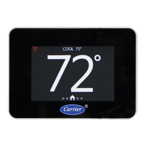
What is the Carrier Connect™ Wi-Fi Thermostat? The Carrier® Connect™ Wi-Fi Thermostat (Part #33CONNECTSTAT) is a thermistor-based wireless thermostat that can sense a 10k type-2 OAT or a remote space or return air sensor and can control up to 4 heating and 3 cooling stages. -
Page 6: Wiring The Carrier® Connect™ Wi-Fi Thermostat
Wiring the Carrier® Connect™ Wi-Fi Thermostat Wiring the Carrier® Connect™ Wi-Fi Thermostat To wire the thermostat to equipment Packaged Rooftop Units Carrier Connect™ Wi-Fi Thermostat Carrier Proprietary and Confidential CARRIER CORPORATION ©2017 Installation Guide All rights reserved... - Page 7 Wiring the Carrier® Connect™ Wi-Fi Thermostat Carrier Connect™ Wi-Fi Thermostat Carrier Proprietary and Confidential CARRIER CORPORATION ©2017 Installation Guide All rights reserved...
- Page 8 Wiring the Carrier® Connect™ Wi-Fi Thermostat Dual fuel systems (Furnace and heat pumps) Carrier Connect™ Wi-Fi Thermostat Carrier Proprietary and Confidential CARRIER CORPORATION ©2017 Installation Guide All rights reserved...
- Page 9 Wiring the Carrier® Connect™ Wi-Fi Thermostat Air Handler or DX Coil/Heat Pump split system Water Source or Non-Carrier Heat Pump Carrier Connect™ Wi-Fi Thermostat Carrier Proprietary and Confidential CARRIER CORPORATION ©2017 Installation Guide All rights reserved...
- Page 10 Wiring the Carrier® Connect™ Wi-Fi Thermostat Air Handler or DX Fan Coil/AC Split System Carrier Connect™ Wi-Fi Thermostat Carrier Proprietary and Confidential CARRIER CORPORATION ©2017 Installation Guide All rights reserved...
-
Page 11: To Wire And Mount The Thermostat
Wiring the Carrier® Connect™ Wi-Fi Thermostat Hydronic Fan Coil To wire and mount the thermostat Turn off 24 Vac power at the equipment circuit breaker or the system switch. Place the thermostat base against your wall to mark drill holes. - Page 12 Attach the base to the wall with the provided screws. Straighten the wires and match your wire configuration to the terminals on the base. Connect each wire individually by pushing down on the color-coded quick connect tab, inserting it into the connector opening, and then releasing the tab.
-
Page 13: To Connect A Remote Input (Sensor Or Contacts)
Turn on the 24 Vac power. The thermostat displays the HOME screen. See HOME (page 27) for details. 10 Configure your system as described in this document. To connect a remote input (sensor or contacts) NOTE Use the specified type of wire and cable for maximum signal integrity. - Page 14 Wiring the Carrier® Connect™ Wi-Fi Thermostat Match wire colors when connecting thermostat to sensor. Wiring for space temperature sensor averaging 4 sensors Carrier Connect™ Wi-Fi Thermostat Carrier Proprietary and Confidential CARRIER CORPORATION ©2017 Installation Guide All rights reserved...
- Page 15 Wiring the Carrier® Connect™ Wi-Fi Thermostat 9 sensors Carrier Connect™ Wi-Fi Thermostat Carrier Proprietary and Confidential CARRIER CORPORATION ©2017 Installation Guide All rights reserved...
-
Page 16: Registering And Setting Up A Mobile Device For Enhanced Access
Downloading the Connect™ App provides enhanced access to your device. 7-day programming is only available on your mobile device. The Connect™ App is available for Apple IOS® at App Store® or at Google Play® for Andriod devices. Search for Carrier Connect™ Thermostat. -
Page 17: Using The Connect Website Or App
Registering and setting up a mobile device for enhanced access Using the Connect website or app After you register for an account, you can access the thermostat by using the app directly or through the Web at connectstat.carrier.com. You can: •... - Page 18 15 minute increments. • Select Copy to apply that schedule to other days of the week. • Adjust the setpoints for each period. Carrier Connect™ Wi-Fi Thermostat Carrier Proprietary and Confidential CARRIER CORPORATION ©2017 Installation Guide All rights reserved...
- Page 19 Displays the name and phone number of the service company or individual who is responsible for servicing the system. NOTE Requires advanced security level to edit these settings. Carrier Connect™ Wi-Fi Thermostat Carrier Proprietary and Confidential CARRIER CORPORATION ©2017 Installation Guide All rights reserved...
-
Page 20: Configuring The System
Swipe up or down to navigate through options and then tap to select one. Swipe on any of the SYSTEM SETTINGS sub-screens to return to the SYSTEM SETTINGS main screen. ○ Carrier Connect™ Wi-Fi Thermostat Carrier Proprietary and Confidential CARRIER CORPORATION ©2017 Installation Guide All rights reserved... -
Page 21: To Configure Advanced System Settings
1-6 hours is started with the value selected here and displayed in the clock location. FAHRENHEIT OR CELSIUS — The temperature scale. °F °F/°C Carrier Connect™ Wi-Fi Thermostat Carrier Proprietary and Confidential CARRIER CORPORATION ©2017 Installation Guide All rights reserved... - Page 22 30 MIN cool-to-heat demands when in AUTO MODE. The timer begins when the MINIMUM OFF 5, 10, 15, 20, 25, 30 MIN TIMER expires. Carrier Connect™ Wi-Fi Thermostat Carrier Proprietary and Confidential CARRIER CORPORATION ©2017 Installation Guide All rights reserved...
- Page 23 NONE or SPACE — The outdoor temperature is acquired by Wi-Fi through the server, OUTDOOR based on the location of the mobile device used to connect the thermostat to a AVERAGE router, or based on the ISP location, if a computer connects the thermostat to a OCCUPANCY router.
- Page 24 DEHUMIDIFIER — Sets the 6th output relay to enable a factory-installed Humidi-MiZer™ for dehumidification or to use the first stage of cooling. • If YES, the 6th relay energizes the Humidi-MiZer™ on the Carrier unit. OVRCL(2) • If OVRCL(2), it uses the first stage of cooling to satisfy a dehumidification demand, but will not overcool the space by more than 2°F.
- Page 25 DISCONNECT WIFI — Disconnects the thermostat from the Wi-Fi network. CAUTION Disconnecting the Wi-Fi requires setting up the Connect Thermostat using the Connect mobile application in order to re-establish Wi-Fi connectivity. INSTALLATION TEST — See the Installation Test (page 37) section for detailed instructions.
- Page 26 FACTORY DEFAULTS — Press and hold the 5 button for 5 seconds to initiate and restore all system setting defaults. Press the CANCEL button to go back to SYSTEM SETTINGS screen. Carrier Connect™ Wi-Fi Thermostat Carrier Proprietary and Confidential CARRIER CORPORATION ©2017 Installation Guide All rights reserved...
-
Page 27: Operating Your System Using The Carrier® Connect™ Wi-Fi Thermostat
Operating your system using the Carrier® Connect™ Wi-Fi Thermostat Operating your system using the Carrier® Connect™ Wi-Fi Thermostat The thermostat supports the following types of constant volume units: • Standard heat/cool unit types with up to 3 stages of mechanical cooling, up to 2 stages of gas or electric heating, and up to 4 stages for non-Carrier heat pumps •... -
Page 28: Cooling
The thermostat's application and configuration determine the specific cooling sequence. It can control up to 2 stages of cooling, with an additional output for a reversing valve, for non-Carrier heat pump applications, or up to 3 stages of cooling for non-heat pump applications. -
Page 29: Heating
Heating The thermostat's application and configuration determine the specific heating sequence. It can control up to 4 stages of heating when configured for non-Carrier heat pump applications, or up to 2 stages of heating for non- heat pump applications. NOTE The heating stages are controlled based on a drift algorithm and the configurable DIFFERENTIAL value (.5°F default). -
Page 30: Humidification
Operating your system using the Carrier® Connect™ Wi-Fi Thermostat Humidification There is occupied and unoccupied humidification on units that are equipped with humidifiers. The following conditions must be true for humidification to operate: • HUMIDIFIER must be set to YES •... -
Page 31: Using The Carrier® Connect™ Wi-Fi Thermostat's Screens
Using the Carrier® Connect™ Wi-Fi Thermostat's screens Using the Carrier® Connect™ Wi-Fi Thermostat's screens HOME The HOME screen is typically what the end user sees. Screen functions • Banner Press the center of the scrolling Banner to switch to the screen indicated by the displayed text. You can ○... -
Page 32: Setpoint
Using the Carrier® Connect™ Wi-Fi Thermostat's screens • Equipment Status — This button is static except when equipment is being activated and then it pulses on and off. If you tap the Fan mode/operation icons, the screen switches to the FAN screen. -
Page 33: Mode
Using the Carrier® Connect™ Wi-Fi Thermostat's screens MODE Use this screen to view and change the current MODE, including: • • HEAT • COOL • AUTO • E- HEAT NOTE The horizontal yellow bar always appears above the current mode. - Page 34 Using the Carrier® Connect™ Wi-Fi Thermostat's screens If cooling equipment is not available, COOL TO DEHUMIDIFY is not adjustable on the thermostat and the blue Dehum Setpoint wheel is not adjustable. HUMIDIFY — not adjustable on the thermostat (the orange Hum Setpoint wheel is not adjustable) if any of the following are true: •...
-
Page 35: Fan
You can only view the program schedule on this screen on the thermostat. You cannot adjust the schedule or setpoints. Permanent program schedule changes require the Connect App. Making temporary changes or pausing the program schedule are outlined in Using the Connect App (page 13). -
Page 36: Holiday
Using the Carrier® Connect™ Wi-Fi Thermostat's screens • The vertical dashed lines separate the program time changes throughout the day. • The times at the bottom of the dashed lines show the schedule. • The vertical yellow dashed line displays the current time of day. -
Page 37: Date And Time
(based on the location of the phone/tablet used to connect the thermostat to a router or based on the ISP location if a computer is used to connect the thermostat to a router). The time and date are synced at the top of each hour automatically, unless the Sync Time To Server option in the SETTINGS >... -
Page 38: Filter
Using the Carrier® Connect™ Wi-Fi Thermostat's screens Screen Name/Description Default and Range PROX SENSITIVITY — change the proximity sensing feature from HIGH to MEDIUM to LOW. MEDIUM Increasing the sensitivity increases the range the sensor can detect presence, but also... -
Page 39: Clean
Using the Carrier® Connect™ Wi-Fi Thermostat's screens CLEAN Stops touchscreen interaction for 10 seconds to allow cleaning the screen with a dry nonabrasive cloth. A 10- second countdown shows on the CLEAN screen and then resumes normal operation. You can use this screen to view software update history, fault history, and system events. Swipe up or down on the vertical yellow Row Indicator to scroll through logged events. -
Page 40: Service
Using the Carrier® Connect™ Wi-Fi Thermostat's screens SERVICE Displays the dealer/installer service contact information. This information is editable using the mobile App, LAN mode transfer and Wi-Fi transfer. Carrier Connect™ Wi-Fi Thermostat Carrier Proprietary and Confidential CARRIER CORPORATION ©2017 Installation Guide... -
Page 41: Installation Test
Installation test Installation test Complete the following to field test the Carrier® Connect™ Wi-Fi Thermostat's outputs. Press the CHANGE button to cycle the MODE screen through the following settings: HEATING (default) — not available in a cooling-only configuration ○ EM HEAT — not available unless a heat pump is configured ○... -
Page 42: Troubleshooting
Heat 1 (Heat Pump) Heat 2 (Heat Pump) Heat 3 (HP w/Emerg Ht) Heat 4 (HP w/Emerg Ht) Heat 1 and Dehumidify Heat 2 and Dehumidify Carrier Connect™ Wi-Fi Thermostat Carrier Proprietary and Confidential CARRIER CORPORATION ©2017 Installation Guide All rights reserved... -
Page 43: Fault Definitions
WI-FI HARDWARE FAULT Communications error occurred with Wi-Fi module (resets after valid message received) ECONOMIZER FAULT Contact closure on remote sensor input, as determined by Economizer Carrier Connect™ Wi-Fi Thermostat Carrier Proprietary and Confidential CARRIER CORPORATION ©2017 Installation Guide All rights reserved... -
Page 44: Recovering From A Power Outage
Date and time The Carrier® Connect™ Wi-Fi Thermostat uses a capacitor to maintain date and time for approximately 2 hours, in order to maintain data during short power interruptions. If the power outage is longer than 2 hours, the date and time will be automatically updated once network connection is re-established. -
Page 45: Document Revision History
SETTINGS Added OCCUPANCY OUTPUT, OCCUPANCY INPUT, and LINE FREQUENCY. To connect a remote input (sensor or Title changed from To connect a remote sensor. C-TS-CP-E-RD contacts) Power specs now N/A. Occ contact N.O. and Fault Input N.O. added to sensor graphic. - Page 48 CARRIER CORPORATION ©2017 A member of the United Technologies Corporation family · Stock symbol UTX · Catalog No. 11-808-579-01 · 11/3/2017...
Need help?
Do you have a question about the Connect and is the answer not in the manual?
Questions and answers