
Related Manuals for Carrier ComfortChoice Touch


Summary of Contents for Carrier ComfortChoice Touch
- Page 1 ComfortChoice Touch Thermostat Designed for ZigBee Wireless Technology USER GUIDE...
-
Page 2: Table Of Contents
TABLE OF CONTENTS PAGE WELCOME ..........THE TOUCH SCREEN . - Page 3 TABLE OF CONTENTS THE BASIC SETUP SCREEN ......23- -37 Screen ..........Filter Replacement Reminder .
- Page 4 TABLE OF CONTENTS SMART RECOVERY ........ZIGBEER WIRELESS TECHNOLOGY .
- Page 5 TABLE OF CONTENTS KEYPAD LOCKOUT FEATURE ......89- -96 Selecting Lockout ........Unlocking the Thermostat .
- Page 6 TABLE OF CONTENTS System Error Messages ....... . Forgotten Lockout Password .
-
Page 8: Welcome
WELCOME This is the Carrier ComfortChoice Touch Programmable Communicating Thermostat (PCT) with ZigBee wireless technology. This unique device’s state-of-the-art technology and easy to use interface makes it easier than ever for you to keep your home comfortable while saving energy and money. -
Page 9: Welcome
WELCOME thermostat also contains advanced wireless communication module that helps you save energy by automatically responding to signals from your energy provider. In the event your energy provider sends a signal to your thermostat, there may be adjustments made to your settings that will help you save energy. -
Page 10: The Touch Screen
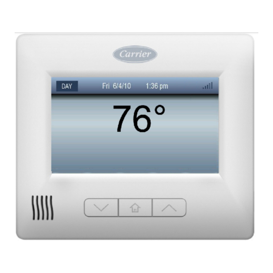
THE TOUCH SCREEN Home - - Inactive The screen provides a clean uncluttered look when not in use, showing the time/date, room temperature, outside temp (if an outside sensor is used), equipment icons and any energy event indicators. See Fig. 1. The vent openings in the lower left corner of the thermostat contain the room temperature sensor. -
Page 11: Home - - Active
THE TOUCH SCREEN Home - - Active Whenever the screen is touched, or the Home button is pressed, the Home Active screen provides the user with all of the selections needed to use the thermostat. The Home Active screen will time-out and return to the inactive mode after 60 seconds. -
Page 12: Physical Buttons
PHYSICAL BUTTONS Located on the cover under the touch screen are three physical buttons: the Up button, the Home button, and the Down button. See Fig. 3. Home Button Use this button to wake up the thermostat, return the thermostat to the Home Inactive state, or return to Home from any screen. -
Page 13: Quick Start
QUICK START Setting the Time and Date The thermostat is equipped to automatically communicate wirelessly with a communication network to obtain date and time information. In some instances the time zone and daylight savings settings may need to be set manually. In the event of a loss of communications, or the lack of a communications network, the time and date can be set manually. - Page 14 QUICK START The time and date are being read from the communication network and the user cannot alter the setting. The time and date are read from the communication network, but your time zone and daylight saving setting must be selected. The time and date need to be manually set.
- Page 15 QUICK START Change the date and time by performing the following steps: 1. Select the Month, Day, Year, Hour or Minute button. 2. Use the up and down arrow buttons to adjust the date and time shown in the top status bar to the desired settings. 3.
-
Page 16: Select The Mode
QUICK START Select the Mode The heating or cooling system is operated using the MODE button to select the desired cooling or heating Mode. The current mode is always displayed above the MODE button on the status bar on the Home screen. Activate the Home Screen to change the mode. - Page 17 QUICK START 2. The Select Mode screen shows the different mode choices available. See Fig. 6. OFF - - Turns the heating and cooling system off. HEAT - - Enables the heating equipment to operate as needed. When the equipment is operating, a red icon will appear over the HEAT TO button.
-
Page 18: Set Or Change The Heating And Cooling Setpoints
QUICK START A11111 Fig. 6 - - Select Mode Set or Change the Heating and Cooling Setpoints Change the heating and cooling setpoints by either using the Up and Down physical arrow buttons on the front of the unit, or by activating the Home screen and using the HEAT TO and COOL TO touch screen buttons. -
Page 19: Basic Thermostat Operation
BASIC THERMOSTAT OPERATION Hold Until The user has selected to follow the program schedule but changes the setpoint temporarily. In addition to the setpoint change, there is a “hold until” time indicating how long this temporary setpoint shall remain active. At the user specified hold until time, the setpoints shall return to their program schedule values. - Page 20 BASIC THERMOSTAT OPERATION Fig. 7 - - The Hold Button...
-
Page 21: Fan Selection
BASIC THERMOSTAT OPERATION Fan Selection The fan distributes air throughout the home for a more even temperature in all spaces. Select the desired Fan mode from one of the two options available: AUTO - - The fan runs only when the heating or cooling equipment is running. - Page 22 BASIC THERMOSTAT OPERATION A11112 Fig. 8 - - The Fan Selection...
-
Page 23: The Basic Setup Screen
THE BASIC SETUP SCREEN Pressing Setup on the Active Home screen opens the Basic Setup menu screen, as shown in Fig. 9. A14011 Fig. 9 - - The Basic Setup Menu Screen... - Page 24 THE ADVANCED SETUP SCREEN Pressing the ADVANCED button opens the Advanced Setup menu screen, as shown in Fig. 10. A11080 Fig. 10 - - The Advanced Setup Menu Screen When you push the Version button, the current software version will be displayed.
-
Page 25: Screen
THE BASIC SETUP SCREEN Screen Pressing the Screen button will display the following screen. A11114 Fig. 11 - - The Screen Menu Pressing the Done button, or not pressing any buttons for 60 seconds, will return to the Basic Setup Screen. - Page 26 THE BASIC SETUP SCREEN Pressing the Adjust Brightness button will switch to the Set Screen Brightness screen. Range: Level 1- -8 The user shall be able to set the backlight level of the home inactive screen to a different setting for each period of the program schedule. The idea being that brighter levels are desirable during the daytime and darker levels are desirable at night.
- Page 27 THE BASIC SETUP SCREEN Pressing the WAKE, DAY, EVENING or SLEEP buttons shall move the adjustment arrows below the selected button. The adjustment arrows will be used to adjust the brightness of the display for that programming period. The Up button selects a brighter level and the Down button selects a darker level.
- Page 28 THE BASIC SETUP SCREEN If the thermostat is put into HOLD, the backlight level shall continue to change, even though the setpoints do not, based on the times of each programmed period. A11116 Fig. 13 - - The Set Screen Brightness Screen When a vacation is active, the home inactive screen backlight level shall be set to the SLEEP setting.
- Page 29 THE BASIC SETUP SCREEN If the Screen Saver button is pressed on the Screen menu, the following screen will be displayed. A11117 Fig. 14 - - The Set Screen Saver Screen This screen allows the user to configure whether a screen saver is displayed if a valid one is saved in the thermostat memory.
- Page 30 THE BASIC SETUP SCREEN If the Clean Screen button is pressed on the Screen menu, the following screen will be displayed. A11118 Fig. 15 - - The Screen Cleaning Screen This screen will allow the user to clean the screen without impacting anything on the thermostat.
-
Page 31: Filter Replacement Reminder
THE BASIC SETUP SCREEN Filter Replacement Reminder The thermostat tells you when it is time to change the filter. When the filter needs to be replaced, the FILTER button will be displayed on the Home Active screen. See Fig. 16. A11081 Fig. - Page 32 THE BASIC SETUP SCREEN A11082 Fig. 17 - - Filter Change Required 3. When the RESET button is pressed, the “Change Filter in” value will reset to its original value, and the reminder will go away. Therefore, the filter should be replaced when RESET is pressed. 4.
- Page 33 A11083 Fig. 18 - - Filter Message Read But Timer Not Reset...
-
Page 34: Filter Replacement Reminder Reset
THE BASIC SETUP SCREEN Filter Replacement Reminder Reset This setup allows the user to reset the filter use timer when the filter is changed prior to the filter reminder message being displayed. 1. Press the Reminders button on the Basic Setup menu screen. 2. - Page 35 THE BASIC SETUP SCREEN 3. Press the Reset button to reset the timer back to its original value. See Fig. 4. Press the DONE button to save the changes and return to the Home Act- ive screen, or press CANCEL to ignore all changes and return to the Basic Setup menu screen.
-
Page 36: Sounds
THE BASIC SETUP SCREEN Sounds The buzzer can be configured to provide audible feedback when the touch screen is pressed. There are two buzzer sounds: A high pitched sound for a valid touch of the display. A low pitched sound for an invalid touch of the display. An invalid touch indicates touching or pressing a non- -functioning button or at- tempting to change a parameter to a value beyond its allowable range. - Page 37 THE BASIC SETUP SCREEN Turn the buzzer on or off by performing the following steps: 1. Select the Sounds button from the Basic Setup menu screen. 2. Select either ON or OFF, and then select the DONE button. See Fig. 21. A11121 Fig.
-
Page 38: Programming The Thermostat
PROGRAMMING THE THERMOSTAT The ComfortChoice Touch thermostat can be set to adjust the temperature of a home according to one’s schedule. Temperatures inside the home can be set to change based on whether or not the home is occupied, or whether residents are awake or asleep. - Page 39 PROGRAMMING THE THERMOSTAT There are four (4) periods within each day: Wake, Day, Evening, and Sleep. The following tables illustrate the All Days program schedule and the Weekday/Weekend program schedule: All Days Program Schedule Monday thru Sunday Time Heating Setpoint Cooling Setpoint Wake 6 AM...
- Page 40 PROGRAMMING THE THERMOSTAT Weekday/Weekend Program Schedule Monday thru Friday Time Heating Setpoint Cooling Setpoint Wake 6 AM 8 AM Evening 5 PM Sleep 10 PM Saturday and Sunday Time Heating Setpoint Cooling Setpoint Wake 8 AM 9:45 AM Evening 6:30 PM Sleep 11:30 PM...
- Page 41 PROGRAMMING THE THERMOSTAT Perform the following steps to open the Schedule screen: 1. Touch the screen or press the Home button to activate the Home screen. 2. Press the Setup button. 3. Press the Schedule button to open the Schedule screen, as shown in Fig. A11122 Fig.
- Page 42 PROGRAMMING THE THERMOSTAT The screen will switch to the appropriate screen when the All Days, Weekday/Weekend, or Each Day button is pressed. See Fig. 23. A11123 Fig. 23 - - The All Days Schedule Screen...
- Page 43 PROGRAMMING THE THERMOSTAT Press the BACK button to return to the Schedule screen, or press the EDIT button to open the Edit Schedule screen shown in Fig. 24. A11124 Fig. 24 - - The All Days Edit Schedule Screen...
-
Page 44: The Edit Buttons
PROGRAMMING THE THERMOSTAT The Edit Buttons Fig. 24 shows the four (4) edit buttons used to manipulate the program schedule. The PERIOD function allows the user to change the schedule for the period indicated in the programming bar. Pressing the Up or Down arrows with the PERIOD button selected will cycle through the periods: Wake, Day, Evening, or Sleep. -
Page 45: View The Schedules
PROGRAMMING THE THERMOSTAT View the Schedules Perform the following steps to view a schedule: 1. Press the SETUP button on the Active Home screen. 2. Press the Schedule button on the Basic Setup screen. 3. Select the Schedule to view – All Days, Weekdays/Weekend, or Each Day. The times and setpoints shown as dashes indicate that the values for each are not the same for every day of the week. - Page 46 PROGRAMMING THE THERMOSTAT Perform the following steps to open the All Days Schedule screen and program the schedule. 1. Press the SETUP button on the Active Home screen. 2. Press Schedule on the Basic Setup screen. 3. Select All Days. A11125 Fig.
- Page 47 PROGRAMMING THE THERMOSTAT 4. Press the EDIT button to open the Edit Schedule screen. See Fig. 26. Pressing the BACK button will return to the Program Schedule menu screen without saving any changes made. A11126 Fig. 26 - - The All Days Edit Schedule 5.
- Page 48 PROGRAMMING THE THERMOSTAT 6. Press the START button to change the starting time of the period. Pressing the up or down arrow buttons with the START button selected will in- crease or decrease the display period start time in 15 minute increments. 7.
-
Page 49: Weekday / Weekend Schedule
PROGRAMMING THE THERMOSTAT Weekday / Weekend Schedule Use the Weekday / Weekend schedule to program all five (5) weekdays (Monday thru Friday) with the same time periods and heating / cooling setpoints, and program both Saturday and Sunday with the same time periods and heating / cooling setpoints but different from the weekday settings. - Page 50 PROGRAMMING THE THERMOSTAT The times and setpoints shown as dashes “- -- -” indicate that the setpoint values are not the same for every day of the week. A11127 Fig. 27 - - The Weekday Schedule...
- Page 51 PROGRAMMING THE THERMOSTAT A11128 Fig. 28 - - The Weekend Schedule Perform the following steps to open the Weekday / Weekend Schedule screen and program the schedule: 1. Press the SETUP button on the Active Home screen. 2. Press the Schedule button on the Basic Setup screen. 3.
- Page 52 PROGRAMMING THE THERMOSTAT 5. Press the PERIOD button to change the schedule for the period indicated in the programming bar. The up or down arrow buttons with the PERIOD button selected cycle through the periods of Wake, Day, Evening, and Sleep.
- Page 53 PROGRAMMING THE THERMOSTAT 9. Press the SAVE button to save changes made to the program schedule and return to the All Days schedule screen. Pressing the CANCEL button will exit the screen without saving the changes made and will return to the Program Schedule Menu screen. 10.
-
Page 54: Each Day Schedule
PROGRAMMING THE THERMOSTAT Each Day Schedule Use the Each Day schedule to program different time periods and heating / cooling setpoints for each day of the week. Fig. 30 shows an example of a Daily Schedule for Wednesday. A11129 Fig. 30 - - Daily Schedule... - Page 55 PROGRAMMING THE THERMOSTAT Perform the following steps to open the Each Day Schedule screen and program the schedule: 1. Press the SETUP button on the Active Home screen. 2. Press the Schedule button on the Basic Setup screen. 3. Press the EACH DAY button. 4.
- Page 56 PROGRAMMING THE THERMOSTAT 8. Press the COOL TO button to change the cooling setpoint. Pressing the up and down arrows with the COOL TO button selected will increase or decrease the cooling setpoint in one (1) degree increments. 9. Perform Step 5. through Step 8. for each day of the week, advancing to other days using the middle two buttons (labeled with the day) on the bottom of the screen.
-
Page 57: Vacation Scheduling
PROGRAMMING THE THERMOSTAT Vacation Scheduling Your thermostat provides a convenient way to program a special heating / cooling schedule while you are away on vacation or for an extended period of time. When Vacation is active, the thermostat still communicates with the ZigBee network and controls the HVAC equipment to the desired setpoints. - Page 58 PROGRAMMING THE THERMOSTAT NOTE: If a vacation schedule already exists, the Vacation Pending screen will open. 4. Use the up and down arrows to set each of the values (Month, Day, Year, and Time). 5. Press the NEXT button and set the values for the Vacation Return Date. See Fig.
- Page 59 PROGRAMMING THE THERMOSTAT 6. Press the NEXT button. The screen will transition to either the Mode Se- lect screen or an Error screen. The Error screen is displayed when the va- cation start date and end date are reversed. See Fig. 34. Fig.
- Page 60 PROGRAMMING THE THERMOSTAT 7. The equipment mode selection is made before entering vacation mode. See Fig. 35. Once vacation mode is active, the equipment mode setting cannot be changed until the vacation is over or ended. See Fig. 38. 8. Select HEAT, COOL, or AUTO and set the desired setpoints. 9.
- Page 61 PROGRAMMING THE THERMOSTAT 10. The currently selected vacation mode will be displayed in the center of the screen. See Fig. 36. 11. Press the CANCEL button to return to the Home Active screen without saving the changes to the vacation schedule. 12.
- Page 62 PROGRAMMING THE THERMOSTAT 14. The vacation confirmation screen will display the vacation schedule to be confirmed. It also shows the duration of the vacation period in days and hours. See Fig. 37. Press the CANCEL button to return to the Home Active screen without saving the changes to the vacation schedule.
- Page 63 PROGRAMMING THE THERMOSTAT 15. Fig. 38 shows how the Home Active screen will look when the vacation mode is active. Fig. 38 - - The Home Active Screen with Active Vacation Mode...
-
Page 64: Vacation Pending Screen
PROGRAMMING THE THERMOSTAT Vacation Pending Screen When vacation mode is pending and the start date/time is less than one (1) month away, the Home Active screen will show the vacation start date and time, as shown in Fig. 39. Fig. 39 - - Vacation Pending Message... -
Page 65: Canceling Or Modifying A Pending Vacation Schedule
PROGRAMMING THE THERMOSTAT Canceling or Modifying a Pending Vacation Schedule If the vacation mode is active and you arrive home earlier than expected, simply press the END button under the Vacation label to end the vacation schedule and return the thermostat to normal settings. Refer to Fig. 38 for the END button location. - Page 66 PROGRAMMING THE THERMOSTAT Cancel a pending vacation by pressing the SETUP button on the Home Active screen. Then press the Vacation button. Perform one of the following on the Vacation Pending screen. See Fig. 40. Press the DELETE button to delete the pending vacation schedule and go back to the settings screen.
-
Page 67: Activating Hold Until During A Vacation Event
PROGRAMMING THE THERMOSTAT Activating HOLD UNTIL during a Vacation Event Setpoints can be modified during a vacation event by pressing the physical up and down arrow buttons or touching the HEAT TO or COOL TO buttons, resulting in a HOLD UNTIL event. See Fig. 41. The system will return to the vacation settings at the end of the HOLD UNTIL time period. -
Page 68: Smart Recovery
SMART RECOVERY The Smart Recovery feature transitions your home from one temperature period (wake, day, evening, sleep) to the next as energy efficiently as possible. Smart Recovery transition times may start up to 90 minutes prior to the next programming period. During Smart Recovery, the thermostat ramps the setpoint from the current room temperature to the next setpoint using small increments. -
Page 69: Zigbeer Wireless Technology
ZIGBEE WIRELESS TECHNOLOGY Your thermostat is equipped with ZigBee wireless technology - similar to Bluetooth - that is used to communicate to an energy portal supplied by the energy provider. If the thermostat is connected to the ZigBee network, up to five signal bars are displayed to show the relative signal strength. -
Page 70: Signal Strength Indicator
ZIGBEE WIRELESS TECHNOLOGY Signal Strength Indicator The signal indicator displays five (5) solid gray bars when the signal is strong, as shown in Fig. 42. The signal indicator displays more empty gray bars as signal strength weakens. The signal strength indicator displays five red empty bars when communication is lost. -
Page 71: Smart Energy Features
SMART ENERGY FEATURES The thermostat is programmed with Smart Energy features that are offered by your energy provider. Depending on the plan offered by the energy provider, you may be enrolled in one or both of the following: Demand Response program Pricing program Demand Response Event You may be enrolled in a Demand Response program offered by your energy... -
Page 72: Event Notification
SMART ENERGY FEATURES Event Notification The thermostat alerts the homeowner to a Demand Response Event that is in progress by showing an Event icon on the screen. Fig. 43 shows a Level 2 Event. A11132 Fig. 43 - - Utility Event Highlighted Icon... - Page 73 SMART ENERGY FEATURES The Demand Response Events have various levels (from 1 to 5) indicating the increasing level of demand response. There is also a Green level, indicating that not enough power is being provided by Green energy sources. There are mandatory levels defined as Emergency, Planned Outage and Service Disconnect.
-
Page 74: Demand Response Event Info Button
SMART ENERGY FEATURES Demand Response Event INFO Button Press the INFO button on the screen, as shown in Fig. 43, for more information during a Demand Response Event. The information screen explains the reason the energy provider is running the event, the time remaining until the event expires formatted as hours:minutes, and the adjustments that were made to your settings. -
Page 75: Customer Override
SMART ENERGY FEATURES Customer Override During most Events Green thru 5, homeowners have the ability to override an event and restore the settings if it becomes uncomfortable inside the house. During certain mandatory Events, the energy provider may be forced to instruct your thermostat to perform a mandatory shut down of heating and cooling equipment for a specific amount of time. -
Page 76: Price Messages
SMART ENERGY FEATURES A11134 Fig. 45 - - End Participation Screen Price Messages You may be enrolled in a program where the price of electricity varies and the energy provider sends messages alerting the thermostat to the price changes. An advantage to using this thermostat is that you can program automatic responses based on the current cost of electricity. -
Page 77: Setting Up A Price Response
SMART ENERGY FEATURES Setting Up a Price Response The thermostat must be programmed with the necessary information in order to respond to price signals. Settings can be changed at any time. Price Tiers The number of pricing tiers is determined by your energy provider. Fig. 46 shows three, color-coded price tiers: Above Normal (yellow), Peak Pricing (orange), and Critical (red). - Page 78 SMART ENERGY FEATURES A11135 Fig. 46 - - The Price Response Screen...
-
Page 79: Price Event Notification
SMART ENERGY FEATURES Price Event Notification When a price event becomes active, the Home Active and the Home Inactive screens will both display the Price Event icon, as shown in Fig. 47. The HEAT TO and COOL TO automatically adjust to the setback temperatures and reflect the color code of the event. -
Page 80: Restore Normal Settings
SMART ENERGY FEATURES Restore Normal Settings Although it is advisable to maintain the setpoint offsets for the duration of the event, normal thermostat settings can be restored at any time after the thermostat has automatically responded to a price signal. Before restoring, first read the information from the energy provider to see what the price level is, how much time is left in the price event formatted as hours:minutes, and what your adjustment was. - Page 81 SMART ENERGY FEATURES Fig. 49 - - Restoring Temperature Settings When YES is pressed, the setpoint offsets are removed, and the setpoints showing on the Home screen no longer have the background color of the pricing event. NOTE: You will be consuming energy at the higher price for the time remaining in the price event.
-
Page 82: Optional Methods
SMART ENERGY FEATURES Fig. 50 - - Price Event Color Disappears from Setpoints Optional Methods Removing offsets from the setpoints during a pricing event can also be done by simply changing the setpoints from the Home Active screen by pressing the physical up and down arrow buttons, or by using the HEAT TO and COOL TO buttons. -
Page 83: Zigbee Messaging
SMART ENERGY FEATURES ZigBee Messaging A Message from the Energy Provider A message icon on the Home Active and Home Inactive screens alert the homeowner to important text messages sent by the energy provider, as shown in Fig. 51. On the Home Active screen, press the UTILITY button to display the message. On the Home Inactive screen, press the mail icon button to display the message. - Page 84 SMART ENERGY FEATURES If the user does not send a confirmation, the message is displayed continuously even after the event expires regardless of the duration, or until the message is replaced by a new message. Fig. 52 - - Messaging Icons The envelope icon changes to an open envelope icon to show that the homeowner read the message and sent the confirmation to the energy provider.
- Page 85 SMART ENERGY FEATURES A11137 Fig. 53 - - The Open Envelope Icon The UTILITY button and the envelope disappear from the screen if: The message expires. The homeowner deletes the message. The energy provider cancels the message.
-
Page 86: A Cancel Message From The Energy Provider
SMART ENERGY FEATURES A Cancel Message from the Energy Provider If the energy provider sends a Cancel Message that requires confirmation, it is shown as a new Utility message on the Home Active screen, as shown in Fig. 54. The message being cancelled is displayed when the user presses the UTILITY button. -
Page 87: Multiple Messages
SMART ENERGY FEATURES Multiple Messages A Filter message could become active during a Utility Message event. In that case, the Home Active screen displays a MESSAGE button instead of a FILTER or UTILITY button. An open or closed envelope is shown with the MESSAGE button based on the read status of the message. - Page 88 SMART ENERGY FEATURES Pressing the MESSAGE button opens the Message screen, as shown in Fig. 56. The user can then read the individual messages by pressing the corresponding buttons. Unread messages are shown with a closed envelope. Fig. 56 - - The Message Screen...
-
Page 89: Keypad Lockout Feature
KEYPAD LOCKOUT FEATURE The thermostat contains a keypad lockout feature that allows the homeowner to either lock some or all of the features of the thermostat. This is particularly useful in controlling the settings and preventing others from adjusting them. The thermostat features two levels of lockout: Lock Everything prevents someone from making any changes to the thermostat. - Page 90 KEYPAD LOCKOUT FEATURE If the entire keypad is locked and the user presses a button, a backlight turns on to maximum brightness for 10 seconds but none of the thermostat settings can be changed. The invalid buzzer signal will beep. If the temperature settings are enabled in the keypad lockout, the setpoints can be changed by the physical buttons or the HEAT TO and COOL TO touch screen buttons.
-
Page 91: Selecting Lockout
KEYPAD LOCKOUT FEATURE When the keypad lockout is set to either option and a utility demand response event, a utility message, or the filter reminder message becomes active, the buttons related to these events are also locked out. This prevents an unauthorized user from overriding a demand response event, deleting a utility message, or resetting a filter timer. - Page 92 KEYPAD LOCKOUT FEATURE Fig. 57 - - Navigate to the Advanced Setup Screen 5. Select one of the two lockout modes (see Fig. 58): Lock Everything Lock All But Temperature Settings The CANCEL button will return to the Advanced Setup screen. A11100 Fig.
- Page 93 KEYPAD LOCKOUT FEATURE 6. When either Lock button is pressed, a screen will appear to allow the user to enter a 4-digit pin code. See Fig. 59. Pressing the CANCEL button will return to the Advanced Setup screen. Pressing the CLEAR button will erase the pin code that is being currently entered.
- Page 94 KEYPAD LOCKOUT FEATURE If more than four digits are entered, the invalid buzzer signal will beep. If less than four digits are entered when the Done button is pressed, the invalid buzzer signal will beep, and the pin code will be erased. Fig.
- Page 95 KEYPAD LOCKOUT FEATURE When keypad lockout is active, the Home Active screen either allows the setpoint to be changed or does not allow any changes. Fig. 61 shows the keypad lockout is set to everything but setpoint. This results in the MODE, FAN, and HOLD buttons being grayed out. The reason that the HEAT TO button is grayed out is because the mode is Cool.
-
Page 96: Unlocking The Thermostat
KEYPAD LOCKOUT FEATURE Unlocking the Thermostat When the Keypad Lockout function is enabled, a Lock icon and an Unlock button appear on the Home Active screen. See Fig. 61. Unlock the thermostat by performing the following steps: 1. Press the Unlock button. 2. - Page 97 KEYPAD LOCKOUT FEATURE Fig. 62 - - Select an Unlock Option Fig. 63 - - Thermostat is Temporarily Unlocked...
- Page 98 KEYPAD LOCKOUT FEATURE If the code is forgotten, call your Energy Service provider, and they will supply you with a code to unlock the system.
-
Page 99: Usb Support
USB SUPPORT The thermostat has a USB port that is located on the right side of the thermostat. When a USB drive is inserted, the USB screen can be accessed by selecting SETUP, then Advanced, and then pressing the USB button as shown in Fig. 10. This will display the USB screen shown in Fig. - Page 100 USB SUPPORT The Download Picture option is used to download a bitmap image to be used as the Screen Saver, which is enabled as described in the Basic Setup section above. The only file format supported at this time is a 480 x 272 8- -bit indexed color bitmap (.BMP) file.
- Page 101 USB SUPPORT Pressing any of the filenames will select that image to be loaded into the thermostat. When the image is being downloaded, the following screen will be displayed as shown in Fig. 66. Fig. 66 - - Downloading a Screen Saver...
- Page 102 USB SUPPORT Once the download of the BMP from the thumb drive to serial flash is complete, the following screen is displayed if the screen saver is not configured to be ON. This will allow the user to turn the screen saver display option ON by pressing YES, or OFF by pressing NO.
- Page 103 USB SUPPORT Once the download of the BMP from the thumb drive to serial flash is complete, the following screen is displayed if the screen saver is configured to be ON. See Fig. 68. Fig. 68 - - Download Complete When YES or DONE are pressed, the downloaded picture will be a screen saver.
-
Page 104: Pre- -Cooling Schedules
PRE- -COOLING SCHEDULES Setting Pre- - Cooling Schedules Pressing Setup on the Active Home screen opens the Basic Setup menu screen, where the Pre- -Cooling button is displayed as shown in Fig. 69. A14011 Fig. 69 - - The Basic Setup Menu Screen... - Page 105 PRE- -COOLING SCHEDULES Pressing the Pre- -Cooling button opens the Pre- -Cooling Setting screen, as shown in Fig.70. A14013 Fig. 70 - - Pre- -Cooling Settings This setup screen allows you to configure two separate cooling periods (Pre- -Cool 1, Pre- -Cool 2) or turn OFF Pre- -Cool if desired. Each of the buttons are defined below: PRE- -COOL –...
-
Page 106: Pre- -Cooling Default Settings
PRE- -COOLING SCHEDULES Pre- - Cooling Default Settings Default settings for Pre- -Cooling 1 and 2 (PC1and PC2) would be as follows: START = 1pm, OFFSET = 2 degrees, DURATION = 1 hour START = 11am, OFFSET = 0 degrees, DURATION = 0 hour When user tries to setup pre- -cool settings, defaults should be pretty close to what may be expected. -
Page 107: Modifying Pre- -Cooling Day Settings
PRE- -COOLING SCHEDULES Modifying Pre- - Cooling Day Settings: The user would then see the screen below allowing them to select which specific days within the previous dates that pre- -cooling should run. They would select each of the days that pre- -cool should run and then hit the SAVE button to complete the configuration. -
Page 108: Pre- -Cooling Message On Home Screen
PRE- -COOLING SCHEDULES Pre- - Cooling Message on Home Screen The Pre- -Cooling message above the Temp display will indicate when Pre- -cooling is in effect. The COOL TO temperature will also be highlighted in blue indicating the offset. The user can also end Pre- -Cooling by setting the Pre- -Cooling functionality OFF on the Pre- -Cool Settings screen. -
Page 109: Pre- -Cooling Interaction With Other Schedules And Events
PRE- -COOLING SCHEDULES Pre- - cool offset interaction with other schedules and events Mode Pre- -cool applies only when the thermostat is in cooling or auto mode and cooling is in demand. Hold When the device is in HOLD, the pre- -cool offset is subtracted from the HOLD cooling setpoint. -
Page 110: Troubleshooting
TROUBLESHOOTING This section provides troubleshooting for some common issues associated with the Carrier ComfortChoice Programmable Communicating Thermostat. Screen is Unresponsive Check if the thermostat screen is locked to unauthorized users. Unlock the thermostat by providing the 4-digit lock code to enable control of the thermostat. -
Page 111: Loss Of Wireless Communications
TROUBLESHOOTING Loss of Wireless Communications Contact your service provider. System Error Messages Communication Error If the User Interface and UIOB cannot communicate with each other, an error message states, “Communication Error Between Thermostat and I/O Board.” Room Air Temperature Sensor Failure If the room air temperature sensor reads less than -50_ F or greater than 150_ F, it is considered failed. -
Page 112: Forgotten Lockout Password
If the thermostat internal memory fails, an error message will be displayed. 997- - 100040- - 4- - R Copyright 2014 Carrier Corp. S 7310 W. Morris St. S Indianapolis, IN 46231 Edition Date: 01/14 Catalog No: OM--- CCZIGSE11--- 01...
Need help?
Do you have a question about the ComfortChoice Touch and is the answer not in the manual?
Questions and answers
How to wire it. Could u show me a picture
To wire a Carrier Touch thermostat, follow these general steps:
1. Turn off power to the HVAC system to avoid electrical shock or damage.
2. Identify wires coming from the wall. Typical wire labels are R (power), G (fan), Y (cooling), W (heating), and C (common).
3. Label the wires according to the terminals they were connected to on the old thermostat.
4. Connect wires to the new thermostat:
- R wire to R terminal
- G wire to G terminal
- Y wire to Y terminal
- W wire to W terminal
- C wire to C terminal (if available; needed for smart thermostats)
5. If using a Power Extender Kit (PEK):
- Connect five wires from the thermostat to the PEK following the labeled guide (Y, W, G, C, R).
- Connect four wires from the PEK to the furnace control board.
6. Ensure all wires are securely inserted and do not come loose.
7. Mount the thermostat on the wall.
8. Restore power and test the system.
Wiring may vary depending on your specific HVAC system. Always refer to the thermostat and furnace manuals.
This answer is automatically generated