Table of Contents
Advertisement
SAFETY CONSIDERATIONS
Read and follow manufacturer instructions carefully. Fol-
low all local electrical codes during installation. All wiring
must conform to local and national electrical codes. Improper
wiring or installation may damage thermostat.
Recognize safety information. This is the safety alert sym-
bol
. When the safety alert symbol is present on equipment
or in the instruction manual, be alert to the potential for person-
al injury.
Understand the signal words DANGER, WARNING, and
CAUTION. These words are used with the safety alert symbol.
DANGER identifies the most serious hazards which will result
in severe personal injury or death. WARNING signifies a haz-
ard which could result in personal injury or death. CAUTION
is used to identify unsafe practices which would result in minor
personal injury or property damage.
GENERAL
Carrier's Comfort Pro programmable fan coil with three-
speed fan operation thermostats are wall-mounted, low-voltage
thermostats which maintain room temperature by controlling
the operation of a heating and/or air conditioning system. This
fan coil model thermostat is capable of supporting fan coil
heat/cool, or heat only and cool only systems. A variety of fea-
tures are provided including battery operation, separate heating
and cooling set points, auto changeover, keypad lockout, and
backlighting. Programming is available for either 2 or 4 periods
per day. The programming interface is a one touch interface,
with the comfort selections Occupied, Unoccupied, and Limit
(Energy Savings Mode). The user can adjust the heating and/or
cooling set points for each of the three comfort selections.
OPERATION
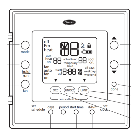
Thermostat Button Identification —
ing buttons are located on the thermostat display. See Fig. 1 for
button locations.
• FAN (1) — Selects whether the fan operates at low
speed (F1), medium speed (F2), high speed (F3), or auto
(only when needed for heating and cooling when in
unoccupied mode)
• HOLD/RUN (2) — Holds the currently selected temper-
ature or runs the scheduled program
• MODE (3) — Selects whether thermostat is set for heat-
ing, cooling, emergency heat, auto (heat and cool as
needed), or off
• UP (4) — Increases the temperature or adjusts the screen
selection up when setting advanced programming
features
• DOWN (5) — Decreases the temperature or adjusts the
screen selection down when setting advanced program-
ming features
Manufacturer reserves the right to discontinue, or change at any time, specifications or designs without notice and without incurring obligations.
Catalog No. 04-53330024-01
Owner's Manual
Part Number 33CSCPACHP-FC
The follow-
Printed in U.S.A.
Programmable Fan Coil
Commercial Thermostat
• DONE (6) — Saves settings when completing a set-up
or programming step
• LIMIT (7) — Indicates occupied heating and cooling
settings for the program period which are predefined and
more energy efficient
• UNOCC (8) — Activates heating and cooling settings
for the unoccupied program period
• OCC (9) — Activates heating and cooling settings for
the occupied program period
• D/H/M SET CLOCK (10) — Activates clock set mode
day/hour/minutes settings
• START TIME (11) — Activates the programming menu,
displaying the programmed start times
• PERIOD (12) — Activates the programming menu, dis-
playing the programmed time periods
• DAYS (13) — Activates the programming menu, dis-
playing three options - all days, weekdays and weekends
off
3
Em
heat
mode
aux
heat
on
2
fan
auto
hold
fan
run
on
1
fan
set
days
schedule
13
Fig. 1 — Thermostat Button Identification
Thermostat On-Screen Indicators —
ing on-screen indicators can be displayed on the thermostat dis-
play. See Fig. 2 for location of indicators.
• Clock (1)
• Fan mode - on or auto (2)
• Selected heating set point; "on" indicates system is in
heating mode (3)
• System is in auxiliary (not used with this thermostat) (4)
• Current temperature (5)
• Thermostat mode is either off or using emergency heat
(Em Heat) (6)
• Fahrenheit units (7)
• Keypad is locked (no padlock means unlocked) (8)
Form 33CS-24SO
Comfort™ Pro
°
F
°
C
actual temp
cool
on:
temporary
hold
all days
start
weekdays
at
weekend
done
OCC
UNOCC
LIMIT
push and hold to set
set
period start time
d/h/m
clock
12
11
10
a33-9220
(Door Open)
The follow-
Pg 1
8-11
Replaces: New
4
5
6
7
8
9
Advertisement
Table of Contents

Related Manuals for Carrier Comfort Pro


Summary of Contents for Carrier Comfort Pro
- Page 1 - all days, weekdays and weekends personal injury or property damage. GENERAL Carrier’s Comfort Pro programmable fan coil with three- speed fan operation thermostats are wall-mounted, low-voltage thermostats which maintain room temperature by controlling °...
-
Page 2: On-Screen Indicators
• Celsius units (9) NOTE: The temporary hold icon will be displayed for 15 • Battery strength indicator (10) minutes. See page 3 for more information on Temporary • Selected cooling set point; "on" indicates system is in Hold Override. cooling mode (first stage of cooling) (11) 4. -
Page 3: Programming Schedules
Changes within a given programming period The Comfort Pro pro- Programming Schedules — are considered temporary changes that require user confirma- grammable thermostat gives the user the option of program- tion by either closing the door or pressing the done button ming for all days, weekdays, or weekends. -
Page 4: Turning Heating And Cooling System Off
bright for 10 seconds. After 10 seconds of no button presses, the backlight returns to a dimmer level until an- other button press occurs. 7. To exit the user configuration screen, press the fan or the done button. 8. Close the thermostat door. For the three speed fan coil there are Using the Fan —... -
Page 5: Troubleshooting
When the thermostat uses electricity, the batteries (if installed) TROUBLESHOOTING take over if the electricity goes out. There are system error messages that may appear on the When powered by batteries, the thermostat's two AA batter- thermostat screen. See text below for possible system error ies should last about one year. - Page 8 Copyright 2011 Carrier Corporation Manufacturer reserves the right to discontinue, or change at any time, specifications or designs without notice and without incurring obligations. Catalog No. 04-53330024-01 Printed in U.S.A. Form 33CS-24SO Pg 8 8-11 Replaces: New...
Need help?
Do you have a question about the Comfort Pro and is the answer not in the manual?
Questions and answers