Table of Contents
Advertisement
Advertisement
Table of Contents

Related Manuals for Hach Polymetron 9500


Summary of Contents for Hach Polymetron 9500
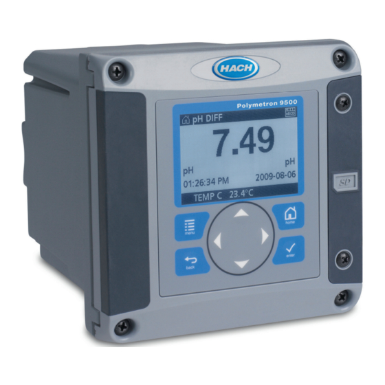
- Page 1 DOC023.52.93058 Polymetron 9500 Controller 05/2015, Edition 6 User Manual...
-
Page 3: Table Of Contents
Table of Contents Specifications ......................3 General information ....................3 Safety information ......................4 Use of hazard information ..................4 Precautionary labels .................... 4 EMC compliance statement (Korea) ..............5 Certification ......................5 Product overview ......................5 Installation ........................7 Mounting components and dimensions ............... - Page 4 Table of Contents Access data and event log files on the SD card ..........39 Firmware updates with SD cards ................ 40 Backup settings to an SD card ................40 Restore settings to the controller ................ 40 Transfer settings to another device ..............40 Using the service port ....................
-
Page 5: Specifications
Specifications Specifications are subject to change without notice. Specification Details Component description Microprocessor-controlled and menu-driven controller that operates the sensor and displays measured values. Operating temperature -20 to 60 ºC (-4 to 140 ºF); 95% relative humidity, non-condensing with sensor load <7 W;... -
Page 6: Safety Information
Safety information N O T I C E The manufacturer is not responsible for any damages due to misapplication or misuse of this product including, without limitation, direct, incidental and consequential damages, and disclaims such damages to the full extent permitted under applicable law. -
Page 7: Emc Compliance Statement (Korea)
Products marked with this symbol indicates that the product contains toxic or hazardous substances or elements. The number inside the symbol indicates the environmental protection use period in years. Products marked with this symbol indicates that the product conforms to relevant South Korean EMC standards. - Page 8 Figure 1 shows the product components. Components may vary according to controller configuration. Contact the manufacturer if parts are damaged or missing. Figure 1 System components 1 Controller 4 Network module (optional) 2 Cable gland assembly 5 High-voltage barrier 3 Additional connection fitting 6 Sensor modules (optional) Sensors and sensor modules The controller accepts up to a maximum of two sensor modules along with one communication...
-
Page 9: Installation
The controller can be mounted to a panel, to a wall or to a vertical or horizontal pipe. A neoprene sealing gasket is included and can be used to reduce vibration. The gasket can be used as a template for panel mounting before the inner gasket component is separated. Installation Mounting components and dimensions C A U T I O N... -
Page 10: Controller Mounting
Controller mounting Figure 3 Surface mounting dimensions 8 English... - Page 11 Figure 4 Panel mounting dimensions Note: If using the bracket for panel mounting (supplied), push the controller through the hole in the panel and then slide the bracket over the controller on the back side of the panel. Use the four 15 mm pan head screws (supplied) to attach the bracket to the controller and secure the controller to the panel.
- Page 12 Figure 5 Pipe mounting (vertical pipe) 10 English...
-
Page 13: High-Voltage Barrier
Figure 6 Top and bottom views High-voltage barrier High-voltage wiring for the controller is located behind the high-voltage barrier in the controller enclosure. The barrier must remain in place except when installing modules or when a qualified installation technician is wiring for power, alarms, outputs or relays. Do not remove the barrier while power is applied to the controller. -
Page 14: Wiring Overview
Refer to the steps in this procedure to prevent ESD damage to the instrument: • Touch an earth-grounded metal surface such as the chassis of an instrument, a metal conduit or pipe to discharge static electricity from the body. • Avoid excessive movement. Transport static-sensitive components in anti-static containers or packages. - Page 15 D A N G E R Electrocution Hazard. Do not connect AC power to a 24 VDC powered model. W A R N I N G Potential Electrocution Hazard. A protective earth (PE) ground connection is required for both 100-240 VAC and 24 VDC wiring applications.
-
Page 16: Alarms And Relays
Alarms and relays The controller is equipped with four unpowered, single pole relays rated 100-250 VAC, 50/60 Hz, 5 amp resistive maximum. Contacts are rated 250 VAC, 5 amp resistive maximum for the AC 14 English... -
Page 17: Wiring Relays
powered controller and 24 VDC, 5A resistive maximum for the DC powered controller. The relays are not rated for inductive loads. Wiring relays W A R N I N G Potential Electrocution Hazard. Always disconnect power to the instrument when making electrical connections. W A R N I N G Potential fire hazard. -
Page 18: Analog Output Connections
Analog output connections W A R N I N G Potential Electrocution Hazard. Always disconnect power to the instrument when making electrical connections. 16 English... -
Page 19: Discrete Input Wiring Connections
W A R N I N G Potential electrocution hazard. In order to maintain the NEMA/IP environmental ratings of the enclosure, use only conduit fittings and cable glands rated for at least NEMA 4X/IP66 to route cables in to the instrument. Two isolated analog outputs are provided. - Page 20 W A R N I N G Potential electrocution hazard. In order to maintain the NEMA/IP environmental ratings of the enclosure, use only conduit fittings and cable glands rated for at least NEMA 4X/IP66 to route cables in to the instrument. Three discrete inputs are provided for switch closure inputs or logic level voltage inputs.
-
Page 21: Connect The Optional Digital Communication Output
12. Refer to the manual supplied with the network module for more details. For information about Modbus registers, refer to http://www.hach-lange.com or http://www.hach.com. Install a Secure Digital (SD) memory card For instructions on how to install an SD card in the controller, refer to Figure 11. -
Page 22: Display
Figure 12 Keypad and front panel overview 1 Instrument display 5 back key. Moves back one level in the menu structure. 2 Cover for secure digital memory card slot 6 menu key. Moves to the Settings Menu from other screens and submenus. 3 home key. -
Page 23: Additional Display Formats
Figure 13 Example of Main Measurement screen 1 Home screen icon 7 Warning status bar 2 Sensor name 8 Date 3 SD Memory card icon 9 Analog output values 4 Relay status indicator 10 Time 5 Measurement value 11 Progress bar 6 Measurement unit 12 Measurement parameter Table 5 Icon descriptions... -
Page 24: Graphical Display
If the controller fails to find connected devices, refer to the Troubleshooting section of this manual. Controller configuration information General information about configuration options is listed in the table. 1. Push the menu key and select Polymetron 9500 SETUP. Option Description SECURITY SETUP Sets the passcode preferences. - Page 25 Option Description RELAY SETUP Configures the controller relays. DISPLAY SETUP Configures the controller display. ADJUST ORDER—View and modify the measurement display order. • SEE CURRENT ORDER—View the current display order • ADD MEASUREMENTS—Add selected measurements to the display • REMOVE MEASUREMENTS—Remove selected measurements from the display •...
-
Page 26: Advanced Operation
When the pass code function is enabled, access to a number of menus and menu options will require a pass code. 1. Push the menu key and select Polymetron 9500 SETUP>SECURITY SETUP>SET PASS CODE. 2. Select DISABLED or ENABLED and push enter. -
Page 27: Configure A 4-20 Ma Output Module
The controller analog outputs can be assigned to represent the measured parameter or secondary measurements such as temperature and calculations. 1. Push the menu key and select Polymetron 9500 SETUP>OUTPUT SETUP. 2. Select OUTPUT 1 or OUTPUT 2. 3. Choose SELECT SOURCE and select a source from the list. Typically the source is one of the sensors attached to the system. - Page 28 6. From the OUTPUT SETUP menu, select ACTIVATION. Use the information in the table below the chosen function to configure the options. 7. If TRANSFER is or will be selected as the ERROR HOLD MODE, or if the transfer will be used during calibration or other functions within the sensor menu, select SET TRANSFER from the OUTPUT SETUP menu and enter the transfer value.
-
Page 29: Logarithmic Output Mode
Logarithmic output mode Figure 14 shows in graph form the operation of the logarithmic output mode. Figure 14 Logarithmic output 1 Output current axis 4 50% value 7 Maximum output current (20 mA) 2 Source value axis 5 Minimum output current (0-4 mA) 3 High value 6 50% output current... -
Page 30: Bilinear Output Mode
(unless the FAIL SAFE is set to YES), or when power is removed from the controller. To select a menu option, highlight the option and push enter. 1. Push the menu key and select Polymetron 9500 SETUP>RELAY SETUP. 2. Select a relay from the list. - Page 31 Option Description PWM CONTROL Relay uses a PWM (Pulse Width Modulation) control depending on a process value FREQ CONTROL Relay switches with a frequency depending on a process value WARNING Relay indicates warning and error conditions in sensors 6. From the RELAY SETUP menu, select SET TRANSFER and choose ACTIVE or INACTIVE. 7.
- Page 32 Option Description LOW DEADBAND Sets the range where the relay remains on after the measured value increases above the low alarm value. For example, if the low alarm is set for 1.0 and the low deadband is set for 0.5, the relay remains on between 1.0 and 1.5. Default is 5% of the range. HIGH DEADBAND Sets the range where the relay remains on after the measured value decreases below the high alarm value.
- Page 33 Option Description OFF DELAY Sets a delay time for the relay to turn off (default: 0 seconds). ON DELAY Sets a delay time for the relay to turn on (default: 0 seconds). Figure 18 Feeder control function 1 Deadband (Phase = Low) 4 OFF delay (phase set high) 7 ON delay (phase set high) 2 Deadband (Phase = High)
- Page 34 Figure 19 Feeder control function (phase low, overfeed timer) 1 Deadband 4 Time (x-axis) 7 Source (y-axis) 2 Setpoint 5 ON delay 3 Overfeed timer 6 OFF delay • Event control function (refer to Figure Figure 21 Figure Option Description SET SETPOINT Sets the value where the relay will turn on.
- Page 35 Figure 20 Event control function (no delay) 1 Source (y-axis) 4 Setpoint 7 OnMax-time 2 High alarm 5 Low alarm 8 OffMax-time 3 Deadband 6 Time (x-axis) Figure 21 Event control function (OnMin timer, OffMin timer) 1 High alarm 4 Low alarm 7 OnMin timer 2 Deadband 5 Time (x-axis)
- Page 36 Figure 22 Event control function (ON/OFF delay) 1 High alarm 3 ON delay 5 Time (x-axis) 2 Low alarm 4 OFF delay 6 Source (y-axis) • PWM control function (refer to Figure Option Description SET MODE AUTO—the relay output works as a PID controller. MANUAL—the signal is controlled by the user through manual adjustment of the % change value.
- Page 37 Figure 23 PWM control function (linear mode) 1 High alarm 4 Low alarm 7 Phase 2 Deadband 5 Period 8 Selected source (y-axis) 3 Setpoint 6 Time (x-axis) • Frequency control function (refer to Figure Option Description SET MODE AUTO—The relay works as a PID controller. MANUAL—the signal is controlled by the user through manual adjustment of the % change value.
-
Page 38: Set Up The Discrete Inputs
Set up the discrete inputs Use these inputs to switch closure inputs or logic level voltage inputs. 1. Push the menu key and select Polymetron 9500 SETUP>DISCRETE INPUT SETUP. 2. Select the desired channel (INPUT 1, INPUT 2 or INPUT 3) and push enter. -
Page 39: Set Up A Calculation
SETTINGS menu. Set up a calculation Two sensors must be installed in the controller. 1. Push the menu key and select Polymetron 9500 SETUP>CALCULATION. 2. Select a menu option and choose from the displayed list or update the entry. Option... -
Page 40: Set The Datalog Mode And Interval
Set the datalog mode and interval Datalog Setup is available if a calculation has been set up. 1. Push the menu key and select Polymetron 9500 SETUP>DATALOG SETUP. Option Description SET MODE Select an option (SNAP SHOT, AVERAGE, MAXIMUM, MINIMUM). -
Page 41: Access Data And Event Log Files On The Sd Card
1. Attach the card reader device to the PC (if necessary) and install the SD card that contains the files in the reader device. 2. In the SD card directory, open the HACH folder. 3. Select the Logs folder. 4. Select a device folder. -
Page 42: Firmware Updates With Sd Cards
1. Find the zip file at http://www.hach-lange.com or http://www.hach.comand copy it to the PC. 2. Extract file(s) from the zip folder and save them to the SD card. 3. Remove the SD card and update the controller and device firmware. Refer to Updating software on page 38. -
Page 43: Using The Service Port
Update the display language 1. Push the menu key and select Polymetron 9500 SETUP>LANGUAGE to display the list of language options. 2. Highlight the language to be used for the controller and push enter. Update the date and time 1. -
Page 44: Maintenance
Maintenance D A N G E R Multiple hazards. Only qualified personnel must conduct the tasks described in this section of the document. Cleaning the controller D A N G E R Always remove power from the controller before performing maintenance activities. Note: Never use flammable or corrosive solvents to clean any part of the controller. - Page 45 Problem Resolution Make sure the SD card is properly oriented. The copper traces should face toward the controller display. Make sure the SD card is fully seated in the slot and the spring lock is engaged. Make sure the SD card is properly formatted with a Fat Secure Digital Memory (SD) card not 32 format.
-
Page 46: Test And Maintenance Menu
Problem Resolution If the sensor and a corresponding module is installed in the controller, refer to the instructions supplied with the Network or Sensor not recognized Sensor Module. Contact Technical Support Perform a Device Scan from the Test/Maintenance menu. Device Missing error message appears Power cycle the controller Test and maintenance menu 1. -
Page 47: Warning And Error Conditions
Option Description MODBUS STATS Displays Error and Good count stats for selected port. • Sensor port 1, 2, 3 or 4 • Network port • Service port • Clear stats SYSTEM DATA Displays the current system current, temperature and voltage data. Warning and error conditions Follow the steps below to acknowledge controller warnings. - Page 48 General (continued) Description Item number Mounting bracket inserts 9177900 Plug, conduit opening (set of 3) 5868700 Power cord kit, with cable gland, 125 VAC, U.S.-style plug 9202900 Power cord kit, with cable gland, 230 VAC, European-style plug 9203000 Screw driver 6134300 SD card reader 9218200...
- Page 50 HACH COMPANY World Headquarters HACH LANGE GMBH HACH LANGE Sàrl P.O. Box 389, Loveland, CO 80539-0389 U.S.A. Willstätterstraße 11 6, route de Compois Tel. (970) 669-3050 D-40549 Düsseldorf, Germany 1222 Vésenaz (800) 227-4224 (U.S.A. only) Tel. +49 (0) 2 11 52 88-320...
Need help?
Do you have a question about the Polymetron 9500 and is the answer not in the manual?
Questions and answers