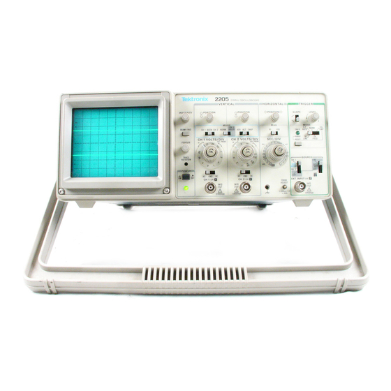
Tektronix 2205 Service Manual
Hide thumbs
Also See for 2205:
- Operator's manual (91 pages) ,
- Service manual (210 pages) ,
- Operator's manual (94 pages)
Table of Contents
Advertisement
Quick Links
Download this manual
See also:
Operator's Manual
Advertisement
Table of Contents
Troubleshooting


Need help?
Do you have a question about the 2205 and is the answer not in the manual?
Questions and answers