Tektronix 2205 Operator's Manual
Hide thumbs
Also See for 2205:
- Service manual (134 pages) ,
- Service manual (210 pages) ,
- Operator's manual (94 pages)
Table of Contents
Advertisement
Quick Links
Advertisement
Table of Contents

Related Manuals for Tektronix 2205


Summary of Contents for Tektronix 2205
- Page 2 070-6717-00 PRODUCT GROUP 46 2205 OSCILLOSCOPE OPERATOR’S MANUAL First Printing October 1987 Tektronix- COMMITTED TO EXCELLENCE...
- Page 3 Tektronix, Inc. Products of Tektronix, Inc. and its subsidiaries are covered by U.S. and foreign patents issued and pending. Information in this publication supersedes that in all previously published material.
- Page 4 NOTICE to the user/operator: The German Postal Service requires that Systems assembled by the operator/user of this instrument must also comply with Postal Regulation, Vfg. 1046/1984, Par. 2, Sect. 1. HINWEIS fur den Benutzer/Betreiber: Die vom Betreiber zusammengestellte Anlage, innerhalb derer dies Gerat eingesetzt wird, mud ebenfalls den Voraussetzungen nach Par.
- Page 5 The German Postal Service has the right to re-test the series and to verify that it complies. TEKTRONIX Bescheinigung des Herstellers/lmporteurs Hiermit wird bescheinigt, da der/die/das 2205 _______ o s c il l o s c o p e AND ALL INSTALLED OPTIONS in Ubereinstimmung mit den Bestimmungen der Amtsblatt-Verfugung 1046/1984 funkentstort ist.
-
Page 6: Table Of Contents
CONTENTS Page Operator’s Safety S u m m a ry ............iv The 2205 Oscilloscope ..............vii SECTION 1-PREPARATION FOR USE Safety ................... .. 1-1 Line Voltage S e le c tio n ..............Line Fuse ..................1-4 Power C o r d ............... - Page 7 Television D isplays..............3 -1 7 TV Field Signals ............3 -1 7 TV Line S ignals............... 3-1 8 Z-Modulation ................3 -1 8 SECTION 4-C H E C K S AND ADJUSTMENTS Trace Rotation ................4-1 Probe Compensation ..............2205 Operator's...
- Page 8 SECTION 5-PERFORM ANCE CHARACTERISTICS SECTION 6 -O P T IO N S AND ACCESSORIES Standard Accessories ..............Options ................... Optional A ccesso ries..............6 -4 APPENDIX A - Magnified Sweep Speeds APPENDIX B - Repackaging for Shipment APPENDIX C - Glossary 2205 Operator's...
-
Page 9: Operator's Safety Summary
DANGER indicates personal-injury hazard that immediately accessible as one reads the marking. Symbols In This Manual This symbol indicates applicable cautionary or other information. maximum input voltage Table 5 -1 . 2205 Operator’s... - Page 10 Use the Proper Power Cord Use only the power cord and connector specified for your product. The power cord must be in good condition. 2205 Operator's...
- Page 11 To avoid explosion, do not operate this product in an explosive atmosphere. Do Not Remove Covers or Panels To avoid personal injury, do not remove the product covers or panels. Do not operate the product without the covers and panels properly installed. 2205 Operator's...
-
Page 12: The 2205 Oscilloscope
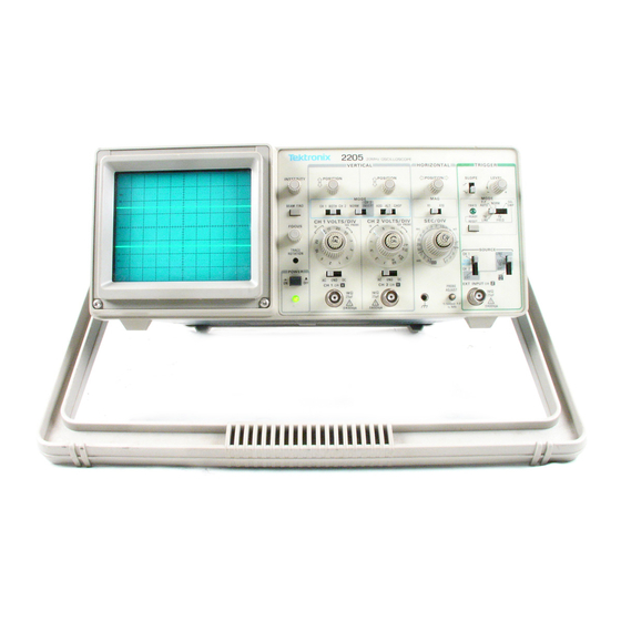
Operator's Safety Summary THE 2205 OSCILLOSCOPE The TEKTRONIX 2205 Oscilloscope is a rugged, lightweight, dual-channel, 20 MHz instrument that features a bright, sharply defined trace on an 80 by 100 mm cathode-ray tube (crt). Its low-noise vertical system supplies calibrated deflection factors from 5 mV to 5 V per division at full bandwidth. - Page 13 Tektronix products; contact the nearest Tektronix Sales Office or Distributor, consult the Tektronix prod uct catalog, or, in the U .S ., call the Tektronix National Marketing Center, toll free at 1 -8 0 0 -4 2 6 -2 2 0 0 .
-
Page 14: Section 1-Preparation For Use
SECTION 1 PREPARATION FOR USE 2205 Operator's... -
Page 16: Safety
LIN E V O L T A G E S E L E C T IO N The 2205 operates from either a 115-V or a 230-V nominal ac power line with any frequency from 48 Hz to 440 Hz. - Page 17 — Standards Association of Australia — British Standards Institution CEE — International Commission on Rules for the Approval of Electric — Equipment — International Electrotechnical Commission NEMA— National Electrical Manufacturer’ s Association SEV — Schweizerischer Elektrotechnischer Verein — Underwriters Laboratories Inc. 2205 Operator's...
- Page 18 Q U ALIFIED PERSONNEL. > > i < LINE VOLTAGE < > o> SELECTOR 2 3 0 V > > l/> TEKTRONIX INC., BEAVERTON. OREGON, U S.A MADE IN HONG KONG Figure 1 -1. Voltage selector switch, fuse, and power-cord receptacle. 2205 Operator's...
-
Page 19: Line Fuse
Maintain adequate airflow to prevent instrument damage from internally generated heat. Before turning on the power, check that the spaces around the air-intake holes on the sides of the cabinet are free of any obstruction to airflow. 2205 Operator’ s... -
Page 20: Initial Start-Up
Attached the power cord. Ensured adequate ventilation around the instrument. Plugged the power cord into the appropriate power source outlet. Now turn on your oscilloscope by pressing in the POWER button. Observe that the Power-On indicator, located below the button, illuminates. 2205 Operator's... - Page 22 SECTION 2 OPERATION 2205 Operator’ s...
- Page 23 ^--^vi_rf?M^% • • : , . ' vV- ; 'V...
- Page 24 NOTE: Numbers on the instrument are keyed to Table 2 -1 .
-
Page 25: Front Panel Organization
Operation FRONT PANEL ORGANIZATION The 2205 front panel is organized to make it easy for you to display signals and make measurements. Referring to the fol- dout illustration, Figure 2 -1 , or to the oscilloscope itself, notice that the front panel is partitioned into four major control sections - Display, VERTICAL, HORIZONTAL, and TRIGGER. - Page 26 CH 2 signals. ALT displays each channel alternately. CHOP switches be tween CH 1 and CH 2 signals during the sweep at 500 kHz rate. VOLTS/DIV Selects vertical Adjust vertical signal to suitable size. sensitivity. 2205 Operator’s...
- Page 27 Set horizontal speed speed. most suited to require ments . Variable Provides continu Extend the slowest (CAL) speed to at least ously variable un calibrated sweep 1.25 s/div. speeds to at least 2.5 times the cali brated setting. 2205 Operator's...
- Page 28 In ab sence of trigger signal. TV FIELD triggers from TV field signals; trig ger polarity must be observed. SGL SWP triggers sweep only once when armed by RESET button; used for displaying or photographing nonrepetitlve or unstable signals. 2205 Operator’s...
- Page 29 Also used for a trigger. single-shot application. Connection for Provide intensity applying external modulation from signal for Intensity independent source. modulation. To Intensity modulate the display, set the right TRIGGER SOURCE control to EXT=Z. 2205 Operator’s...
-
Page 30: Learning The Controls
PROBE ADJUST terminal. If necessary, adjust the TRIGGER LEVEL control to get a stable display. 3. Change the Channel 1 input coupling to GND and use the Channel 1 POSITION control to align the baseline trace to the 2205 Operator’s... - Page 31 VERTICAL MODE control to CH 2 INVERT and notice the ef fect. Then set the right MODE to ADD. What happens to the control waveforms? Finally, return the middle MODE control to NORM. What waveform is displayed now? 2205 Operator’ s...
-
Page 32: Display Controls
Operation Congratulations! You now know how to use the 2205 front-panel controls to display signals and move them about on the screen. The remainder of this section gives you more information about the controls and offers suggestions for their use. Section 3 ex... -
Page 33: Channel Selection
If in doubt about the relative timing of CH 1 and CH 2 signals, experienced operators set the TRIGGER SOURCE to either CH 1 or CH 2. 2205 Operator’ s... -
Page 34: Horizontal Controls
TRIGGER CONTROL For most signals, the trigger-control settings that will yield hands-off triggering are: MODE P-P AUTO SOURCE VERT MODE 2-10 2205 Operator's... -
Page 35: Which M Ode To Use
TV FIELD - This mode triggers the sweep at the beginning of a television field. To change the TV field being displayed, you must interrupt the trigger signal by setting the input coupling switch momentarily to GND then back either DC or AC until the desired field is displayed. 2-11 2205.Operator’ s... -
Page 36: Source
CONNECTING SIGNALS The signal adapter supplied with the instrument is usually the most convenient way to connect a signal to the 2205. These signal adapters are shielded to prevent pickup of electromag netic interference. When connected to the 2205 input, a signal 2-12 2205 Operator’s... -
Page 37: Waveform Fidelity And Probe Grounds
- may work for a signal ground. Fast signal transitions will be highly distorted, and extra neous noise will be induced without the probe ground connec tion, and/or with extra ground connections from the 2205 to the circuit being tested. Probe Compensation (Optional 10X Probe) Misadjustment of probe compensation is a common source of measurement error. -
Page 38: Coaxial Cables
To maintain good waveform fidelity and accuracy, use only high- quality, low-loss coaxial cables. When you use 50 XI or 75 XI coaxial cable, attach a matching external terminator. Some high frequency response will be lost without external termination. 2-14 2205 Operator's... - Page 39 SECTION 3 APPLICATIONS 2205 Operator's...
-
Page 41: Amplitude Measurements
Applications This section describes how to make specific types of measure ments with your 2205 Oscilloscope. Before performing any pro cedure, be sure you are familiar with the information contained Operator's Safety Summary in the and in Section 1. Preset the... - Page 42 This will eliminate trace width from the measurement. 8. Calculate the peak-to-peak voltage, using the following for mula: VOLTS/DIV vertical Vp-p deflection setting (10X Probe)* (divisions) * lf a IX probe is being used for the measurement, use the IX VOLTS/DIV setting. 2205 Operator's...
-
Page 43: Instantaneous Voltage
If using Channel 2, ensure that the center VERTI CAL MODE selector (NORM, CH 2 INVERT), is set to NORM. 5. If necessary, repeat Step 3 using a different horizontal ground reference line that allows the waveform in Step 4 to be displayed on screen. 2205 Operator’ s... - Page 44 9. Calculate the instantaneous voltage, using the following for- mula: VOLTS/DIV Instan polarity vertical setting taneous deflection (+ or - ) (10X Probe) Voltage (divisions) * lf the signal adapter is being used for the measurement, use the IX VOLTS/DIV setting. 2205 Operator’ s...
-
Page 45: Algebraic Addition
This ensures the great est dynamic range for ADD mode operation. 4. To attain similar responses from both channels, set the Channel 1 and Channel 2 input coupling selectors to the same position. 2205 Operator's... -
Page 46: C Om M On-M Ode Rejection
VOLTS/DIV Variable controls. 1. Apply the reference signal to either the CHI or the CH2 input connector and set the left VERTICAL MODE selector to dis play the channel used. 2205 Operator's... - Page 47 0% line on the crt. 4. Horizontally position the waveform so that its topmost fea tures cross the center vertical graticule line (see Fig ure 3 -4 ). 2205 Operator’s...
-
Page 48: Time Measurements
2. Adjust the TRIGGER LEVEL control to obtain a stable display. 3. Set the SEC/DIV control to display between one and two complete repetitions of the waveform. Check that the SEC/ DIV variable control is in the CAL detent. 2205 Operator's... - Page 49 Duration ---------------------------------------- magnification factor EXAMPLE. In Figure 3 -5 , the distance between the time meas urement points is 8.3 divisions, and the SEC/DIV setting is 2 ms per division, HORIZONTAL MAG is set to X I. 2205 Operator'8...
-
Page 50: Period And Frequency
0% graticule line and the top of the waveform touches the 100% graticule line. 4. Horizontally position the display so the 10% point on the waveform intersects the second vertical graticule line (Fig ure 3 -6 , Point A). 3-10 2205 Operator's... - Page 51 In Figure 3 -6 , the horizontal distance between the 10% and 90% amplitude points is 5 divisions, and the SEC/DIV switch is set to 1 ps per division. HORIZONTAL MAG is set to X I. 3-11 2205 Operator’ s...
-
Page 52: Tim E Difference Between Pulses On Tim E-R Elated Signals
Rise Time 5. p.s Tim e Difference Between Pulses on Tim e-R elated Signals The calibrated sweep speed and dual-trace features of the 2205 allow measurement of the time difference between two separate events. To m easure.tim e difference, use the following proce... - Page 53 In Figure 3 -7 , the. SEC/DIV control is set to 50 per division and HORIZONTAL MAG is set to X I 0. The horizontal difference between waveform measurement points is 4 .5 divi sions. 50 us/div x 4 .5 div Time 22.5 jis Difference 2205 Operator’s 3-13...
-
Page 54: Phase Difference
In a similar manner to the preceding measurement, you can make a phase comparison between two signals of the same fre quency using the dual-trace feature of the 2205. This method of phase-difference measurement can be used for signals with frequencies up to the limit of the vertical deflection system. - Page 55 45° per division. Substituting the given values into the phase-difference formula: Phase Difference = 0 .6 div x 45°/div = 27°. CHANNEL 1 CHANNEL2 MEASURE TIME FROM A TO B HORIZONTAL DIFFERENCE Figure 3 -8 . Phase difference. 2205 Operator’ s 3-15...
- Page 56 Substituting the given values into the phase difference formula: Phase Difference = 6 div x 4.5 °/d iv = 27°. CHANNEL 1 (REFERENCE) CHANNEL 2 (COMPARISON) MEASURE TIME FROM A T O B 6 7 1 7 - Figure 3 -9 . High-resolution phase difference. 3-16 2205 Operator's...
-
Page 57: Television Displays
Applications TELEVISION DISPLAYS TV Field Signals The 2205 television feature can be used to display TV field sig nals. To do so, proceed as follows: 1. Set the TRIGGER MODE selector to TV FIELD and set the SEC/DIV control to 2 ms. -
Page 58: Tv Line Signals
It can also be used in any situation where external con trol of the brightness of some or all of the trace is required. The Z, or intensity, modulation feature is operated in the follow ing manner: 3-18 2205 Operator's... - Page 59 Z-modulation is seen as gaps in the trace at the modulation frequency. The size of the gap depends upon the m ark-to-space ratio of the Z-modulation signal. The positive going portion of the Z-modulation signal decreases display brightness. 3-19 2205 Operator's...
- Page 61 SECTION 4 CHECKS AND ADJUSTMENTS 2205 Operator’ s...
-
Page 63: Trace Rotation
1. Preset instrument controls (as given in Learning the Con trols, in Section 2, Operation) and obtain a baseline trace. 2. Attach the two optional X I 0 probes to the CHI and CH2 in put connectors. 2205 Operator's... - Page 64 (Figure 4 -1 , top tra c e ). CORRECT (FLAT) OVER COMPENSATED (OVERSHOOT) UNDER COMPENSATED (ROLLOFF) 6 7 1 7 - 1 3 Figure 4 -1 . Probe compensation. 2205 Operator’s...
- Page 65 10. Obtain a 5-division signal display and vertically center the trace. 11. Repeat step 7 for the Channel 2 probe. LF COMP ROTATING SLEEVE (§ C --------- 1 — PROBE \ 6 7 1 7 -1 4 Figure 4 -2 . Locating the low-frequency compensation adjustment. 2205 Operator’s...
- Page 67 SECTION 5 PERFORMANCE CHARACTERISTICS 2205 Operator's...
- Page 69 +20°C and +30°C, has had a warm -up period of at least 20 min utes, and is operating at an ambient temperature between 0°C and +40°C (unless otherwise noted). Environmental characteristics are given in Table 5 -2 . The 2205 meets requirements...
- Page 70 0.75 division or less (Variable Switch Rotation control in CAL detent). With VOLTS/DIV Variable 1.0 division or less. Control Rotation With Channel 2 1.5 divisions or less. Inverted Channel Isolation Greater than 100 to 1 at 10 MHz. 2205 Operator’s...
- Page 71 -p at 10 kHz or less. Trigger Level Range +15 divisions referred to the NORM Mode appropriate vertical input. At least ± 1 .6 V, 3.2 V p-p. EXT Source At least ± 1 6 V, 32 V p-p. EXT/10 Source 2205 Operator’s...
- Page 72 Position Control Range in X I and to 100th division in X I 0, will position past the center vertical graticule line. Registration of Unmagni 0.2 division or less, aligned to fied and Magnified Traces central vertical graticule line. 2205 Operator’ s...
- Page 73 System. Phase Difference Between ± 3 ° from dc to 50 kHz. X - and Y-Axis Amplifiers PROBE ADJUSTMENT SIGNAL OUTPUT Voltage into 1 M f l Load 0.5 V ± 5%. 1 kHz ± 20%. Repetition Rate 2205 Operator's...
- Page 74 Line Fuse UL198.6, 3AG (V» x 1V4 inch) 115 V Setting 0.75 A Slow 230 V Setting 0.5 A, Slow CATHODE-RAY TUBE Display Area 80 by 100 mm. Standard Phosphor GH (P31). Nominal Accelerating 1800 V ±10%. Voltage 2205 Operator's...
- Page 75 55 Hz. 30 g, half-sine, 11-m s du Shock (Operating and Nonoperating) ration, three shocks per axis each direction, for a total of 18 shocks. Meets VDE 0871 Class B. Radiated and Conducted Emission Requirements 2205 Operator’s...
- Page 76 Handle With 5 1 6 m m ( 2 0 .3 in ). Extended Figure 5 -1 . Maximum input voltage versus frequency derating curve for CH 1 OR X, CH 2 OR Y, and EXT INPUT connectors. 2205 Operator’s...
- Page 77 SECTION 6 OPTIONS AND ACCESSORIES...
- Page 79 Tables 6-1 and 6 -2 . For additional information about instrument options and other optional accessories, consult the current Tektronix Product Catalog or contact your local Tektronix Sales Office or distributor. STANDARD ACCESSORIES Each instrument is shipped with the following standard accesso...
- Page 80 Options and Accessories results with clarity and credibility. Option 1C provides the Tektronix C -5 C Option 04 Low-cost Camera for use with your oscilloscope. Option IK When this option is specified, a K212 Portable Instrument Cart is included in the shipment.
- Page 81 Power Cords Instruments are shipped with the detachable power cord and fuse configuration ordered by the customer. Table 6-1 identifies the Tektronix part numbers for international power cords and as sociated fuses. Additional information about power cord options Preparation for Use.
- Page 82 Power Cord, 2.5 m 161-010 4-08 Fuse, 0.5 A, 250 V, 159-003 2-00 3AG, i/4"x 1V4", Slow Option A5 (Switzerland) Power Cord, 2.5 m 161-016 7-00 Fuse, 0.5 A, 250 V, 159-0032-00 3AG, 1 1 x 1i/4", Slow 2205 Operator's...
- Page 83 016-056 6 -0 0 Probe, 10X, 2 m, with P6103 accessories Alternative Power Cords European 020-085 9 -0 0 United Kingdom 0 20-086 0-00 Australian 0 20-086 1-00 North American 0 20-086 2-00 Switzerland 020-086 3 -0 0 2205 Operator's...
- Page 84 0 1 6 -0 7 8 5 -0 0 Portable Power Supply 1105 Battery Pack 1106 Oscilloscope Cameras C -5 C Option 04 Low-cost C -7 Option 03 Motorized and Option 30 Portable Instrument Cart K212 0 7 0 -6 71 6-00 2205 Service Manual 2205 Operator’s...
- Page 85 .2 ms 20 /is .1 ms 10 /is 50 /is 5 /is 20 /is 2 /is 10 /is 5 /is .5 /is .2 ps 2 /is .1 ps .5 /is 50 ns .2 /is 20 ns 10 ns 2205 Operator's...
- Page 87 275 pounds. 2. If it is to be shipped to a Tektronix Service Center for service or repair, attach a tag to the instrument showing the follow ing: Owner (with address), name of the person at your firm who can be contacted, complete instrument type and serial number, and a description of the service required.
- Page 89 Channel 2 (CH 2 )—Displays only Ch 2 on the screen. Channel 2 Invert (CH 2 INVERT)—Inverts the polarity of CH 2. (See OTHERS for polarity.) CHOP—The scope will draw part of CH 1, then part of CH 2 by switching back and forth. 2205 Operator’ s...
- Page 90 Channel 2 (CH 2 )—Selects CH 2 signals to trigger the time base. External (EXT)—Selects external signals to trigger the time base. External 10 (EXT/10)—Selects external signal, divides it by 10, and connects it to the trigger circuit. LEVEL—Determines signal level at which the trigger will occur. 2205 Operator’s...
- Page 91 Divisions—The lines that divide CRT display area units into X and Y components. Graticule—The square boxes formed by lines on the CRT face. Hertz—The basic unit of frequency. Ohm (H )—The basic unit of resistance. Polarity—The positive (+) or negative (-) direction of voltage or current. 2205 Operator's C -3...
Need help?
Do you have a question about the 2205 and is the answer not in the manual?
Questions and answers