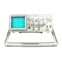
Sign In
Upload
Manuals
Brands
Tektronix Manuals
Test Equipment
2205
Tektronix 2205 Manuals
Manuals and User Guides for Tektronix 2205. We have
4
Tektronix 2205 manuals available for free PDF download: Service Manual, Operator's Manual
Tektronix 2205 Service Manual (210 pages)
Brand:
Tektronix
| Category:
Test Equipment
| Size: 20.5 MB
Table of Contents
Table of Contents
7
List of Illustrations
10
List of Tables
11
Operators Safety Summary
12
Servicing Safety Summary
13
Specification
15
Introduction
15
Accessories
15
Operating Information
23
Preparation for Use
23
Instrument Cooling
23
Line Fuse
23
Line Voltage Selection
23
Safety
23
And Indicators
25
Power and Display
25
Vertical
25
Horizontal
27
Trigger
27
Rear Panel
28
Operating Considerations
29
Graticule
29
Connecting Signals
29
Operator's Checks and Adjustments
30
Initial Setup
30
Trace Rotation Adjustment
30
PROBE COMPENSATION (Option 10X Probe)
31
Theory of Operation
33
Section Organization
33
Integrated Circuit Descriptions
33
General Description
33
Detailed Circuit Description
35
Vertical
35
Trigger Amplifiers and Switching
38
Trigger Generator
40
Sweep Generator and Logic
41
Horizontal
43
Z-Axis Amplifier
45
Power Supply and Probe Adjust
46
Introduction
51
Purpose
51
Performance Check Interval
51
Structure
51
Test Equipment Required
51
Limits and Tolerances
51
Preparation for Checks
51
Index to Performance Check Steps
53
Vertical
54
Initial Control Settings
54
Procedure Steps
54
Variable Range
54
Check Bandwidth
54
Check Channel Isolation
55
Check Common-Mode Rejection Ratio
55
Horizontal
56
Initial Control Settings
56
Procedure Steps
56
Check Timing Accuracy and Linearity
56
Check Position Range
57
Check Variable Range
57
Check X Gain
57
Check X Bandwidth
58
Trigger
59
Initial Control Settings
59
Procedure Steps
59
Check Internal Triggering
59
Check External Trigger Ranges
60
Check External Triggering
60
Check Single Sweep Operation
60
External Z-Axis and Probe Adjust
62
Initial Control Settings
62
Procedure Steps
62
Check External Z-Axis Operation
62
Check Probe Adjust Operation
62
Introduction
63
Purpose
63
Structure
63
Test Equipment Required
63
Limits and Tolerances
63
Repairs
63
Preparation for Adjustment
63
Index to Adjustment Procedure Steps
65
Power Supply and Crt Display
66
Adjust CRT Grid Bias
66
Check/Adjust Power Supply DC Levels
66
Initial Control Settings
66
Procedure Steps
66
Adjust Astigmatism
67
Adjust G Eom Etry
67
Adjust Trace Alignment
67
Vertical
68
Adjust Channel 1 Variable Balance
68
Adjust Channel 2 Variable B a Lan Ce
68
Initial Control Settings
68
Procedure Steps
68
Adjust Channel 2 Invert Balance
69
Adjust Vertical G Ain
69
Check Deflection Accuracy and VOLTS/DIV Variable Range
69
Check Input Coupling
69
Adjust Attenuator Compensation
70
Check Position Range
70
Adjust CHOP Switch B a la N Ce
71
Adjust High-Frequency Compensation
71
Check ADD MODE O Peration
71
Check Bandwidth
72
Check Channel Isolation
72
Check Common-Mode Rejection Ratio
72
Horizontal
74
Initial Control Settings
74
Procedure Steps
74
Adjust 1-Ms Tim Ing
74
Adjust Magnifier Gain
74
Adjust Magnifier Registration
74
Adjust 0.1-M S and 0.1 -Ns T IM Ing
75
Adjust High-Speed Timing
75
Check Position Range
75
Check Variable Range
75
Check Timing Accuracy and Linearity
75
Check Sweep Holdoff
77
Check X Bandwidth
77
Trigger
78
Adjust Auto Level
79
Check Internal Triggering
79
Check External Trigger Range
80
Adjust Slope Balance
79
Check Single Sweep Operation
80
Check External Z-Axis Operation
81
Check Probe Adjust Operation
81
Adjust Trigger Offset
78
Adjust Trigger Sensitivity
78
S Ettin G S
78
Procedure Steps
78
External Z-Axis and Probe Adjust
81
Initial Control Settings
81
Procedure Steps
81
Maintenance
83
Static-Sensitive Components
83
Preventive Maintenance
84
General Care
84
Inspection and Cleaning
84
Introduction
84
Lubrication
86
Periodic Readjustment
86
Semiconductor Checks
86
Introduction
87
Troubleshooting
87
Troubleshooting Aids
87
Troubleshooting Equipment
88
Troubleshooting Techniques
88
Corrective Maintenance
92
Introduction
92
Maintenance Aids
92
Maintenance Precautions
92
Obtaining Replacement Parts
92
Ribbon-Cable Connections
93
Transistors and Integrated Circuits
94
Soldering Techniques
94
Removal and Replacement Instructions
95
Options and Accessories
101
Option 1C
101
Option Ik
101
Option 1R
101
Option It
101
Option 02
101
Option 22
101
Option 23
102
Option 24
102
International Power Cords
102
Optional Accessories
102
Standard Accessories
104
Replaceable Electrical Parts
105
Diagrams
134
Section 10 REPLACEABLE MECHANICAL PARTS
136
Advertisement
Tektronix 2205 Service Manual (134 pages)
Brand:
Tektronix
| Category:
Test Equipment
| Size: 6.69 MB
Table of Contents
Instrument Serial Numbers
2
Table of Contents
5
List of Illustrations
8
List of Table
9
Operators Safety Summary
10
Grounding
10
Symbols
10
Use the Proper Power Cord
10
Servicing Safety Summary
11
Power Source
11
Specification
13
Accessories
13
Performance Conditions
13
Electrical Characteristics
14
Environmental Characteristics
18
Mechanical Characteristics
19
Instrument Dimensional Drawing
20
Operating Information
21
Preparation for Use
21
Safety
21
Line Voltage Selection
21
Voltage Selector Switch
22
Controls, Connectors and Indicators
23
Power and Display
23
Vertical
23
Front Panel Controls
24
Horizontal
25
Trigger
25
Rear Panel
26
Operating Considerations
27
Graticule
27
Connecting Signals
27
Signal Adapter
27
Operator's Checks and Adjustments
28
Probe Handling
28
Coaxial Cables
28
Initial Setup
28
Probe Compensation
29
Theory of Operation
31
General Description
31
Section Organization
31
Linear Devices
31
Triggering
32
Sweep
32
Z-Axis
32
Detailed Circuit Description
33
Attenuators
33
Input Coupling
33
Input Attenuator
33
Source Follower
34
Vertical Preamplifiers
34
Paraphase Amplifier
34
Channel Switch Logic
35
Block Diagram of the Channel Switching
35
Trigger Amplifiers and Switching
36
Internal Trigger
36
Vertical Output Amplifier
36
Internal Trigger Amplifier
37
External Trigger Amplifier
37
Trigger Generator
38
Trigger Level Circuit
38
Trigger Level Comparator
38
Sweep Generator and Logic
39
Miller Sweep Generator
39
Block Diagram of the Sweep Generator and Logic
39
Sweep Logic
40
P-P Auto
40
Single Sweep
40
Norm
40
X-Y Amplifier
41
Horizontal Preamplifier
41
Block Diagram of the Horizontal Amplifier
41
Z-Axis Amplifier
42
Horizontal Output Amplifier
42
DC Restorer
43
Simplified Diagram of the DC Restorer
43
CRT Supply
44
Power Supply and Probe Adjust
44
Focus Circuit
44
AC Power Input
44
Current Source
45
Current Switching
45
Block Diagram of the Power Supply
45
Regulator
46
Inverter
46
Low-Voltage Supplies
46
Line Signal
47
Probe Adjust
47
Performance Check Procedure
49
Performance Check Interval
49
Structure
49
Limits and Tolerances
49
Test Equopment Required
50
Index to Performance Check Steps
51
Initial Control Settings
52
Check Deflection Accuracy and Variable Range
52
Deflection Accurate Limits
52
Check Channel Isolatic
53
Check Common Mode - Rejection Ratio
53
Check Timing Accuracy and Linearity
54
Check Position Range
55
Check Variable Range
55
Check X Gain
55
Settings for Timing Accuracy Checks
55
Check X Bandwidth
56
Check Internal Triggering
57
Check External Triggering
58
Check External Trigger Range
58
Check Single Operation
58
External Z-Axis and Probe Adjust
60
Check External Z-Axis Operation
60
Check Probe Adjust Operation
60
Adjustment Procedure
61
Adjustments Affected by Repairs
61
Test Equipment Required
61
Preparation for Adjustment
61
Power Supply and CRT Display
64
Power Supply Limits
64
Adjust Astigmatism
65
Adjust Trace Alignment
65
Adjust Geometry
65
Adjust Channel 1 Variable Balance
66
Adjust Channel 2 Variable Balance
66
Adjust Channel 2 Invert Balance
67
Adjust Vertical Gain
67
Check Input Coupling
67
Adjust Attenuator Compensation
68
Attenuator Trimmer Adjustments
68
Check Vertical Alt Operation
69
Adjust CHOP Switch Balance
69
Check ADD Mode Operation
69
Adjust High-Frequency Compensation
69
Check Bandwidth
70
Check Channel Isolation
70
Check Common-Mode Rejection Ratio
70
Adjust 1-Ms Timing
72
Adjust Magnifier Gain
72
Adjust Magnifier Registration
72
Adjust X-Axis Gain
74
Adjust X Offset
74
Maintenance
81
Static-Sensitive Components
81
Relative Susceptibility to Static-Discharge Damage
81
Preventive Maintenance
82
Exterior
82
General Care
82
Interior
82
VOLT/DIV and SEC/DIV Switches
83
Lubrication
84
Semiconductor Checks
84
Periodic Readjustment
84
Troubleshooting
85
Troubleshooting Aids
85
Schematic Diagrams
85
Circuit Board Locations
85
Troubleshooting Equipment
86
Component Color Coding
86
Semiconductor Lead Configurations
86
Check Control Settings
86
Check Associated Equipment
87
Visual Check
87
Isolate Trouble to a Circuit
87
Check Power Supplies
87
Check Circuit Board Interconnections
88
Check Voltages and Waveforms
88
Check Individual Components
88
Integrated Circuits
89
Diodes
89
Resistors
89
Inductors
89
Corrective Maintenance
90
Maintenance Precautions
90
Obtaining Replacement Parts
90
Ordering Parts
90
Ribbon-Cable Connections
91
Transistors and Integrated Circuits
92
Soldering Techniques
92
Multi-Connector Holder Orientation
92
Removal and Replacement Instructions
93
Cabinet
93
Cathode-Ray Tube
94
Power Transformer
94
Mains Input Circuit Board
95
Timebase/Attenuator Circuit Board Assembly
95
Front-Panel Circuit Board
96
Main Circuit Board
96
Options and Accessories
99
Option 1K
99
Option 1R
99
Option 1T
99
Option 23
100
Option 24
100
Optional Accessories
100
Standard Accessories
102
Replaceable Electrical Parts
103
List of Assemblies
103
Component Number
103
Mfr.code
103
Cross Index
104
Tektronix 2205 Operator's Manual (91 pages)
Brand:
Tektronix
| Category:
Test Equipment
| Size: 2.17 MB
Table of Contents
Table of Contents
6
Operator's Safety Summary
9
The 2205 Oscilloscope
12
Section 1-Preparation for Use
14
Safety
16
Line Voltage S E Le C Tio N
16
Line Fuse
19
Power C O R D
19
Instrument C O O Lin G
19
Initial Start-Up
20
Front Panel Organization
25
Controls, Connectors, and Indicators
25
Learning the Controls
30
Display Controls
32
Vertical Controls
32
Input Coupling
32
Channel Selection
33
Add and Invert
33
CHOP or ALT
33
Trigger Controls
34
Which M Ode to Use
35
Source
36
Slope
36
Level
36
Horizontal Controls
34
Sweep Speed S Election
34
Magnifying Waveform Details
34
Connecting Signals
36
Waveform Fidelity and Probe Grounds
37
Probe Compensation
37
Probe H Andlin G
37
Coaxial Cables
38
Amplitude Measurements
41
P Eak-To-P Eak Voltage
41
Instantaneous Voltage
43
Algebraic Addition
45
C Om M On-M Ode Rejection
46
Amplitude Comparison (Ratio)
46
Tim E Duration
48
Time Measurements
48
Period and Frequency
50
Rise Time
50
Tim E Difference between Pulses on Tim E-R Elated Signals
52
Phase Difference
54
Television Displays
57
TV Field Signals
57
TV Line Signals
58
Z-Modulation
58
Trace Rotation
63
Probe Compensation
63
Advertisement
Tektronix 2205 Operator's Manual (94 pages)
Brand:
Tektronix
| Category:
Test Equipment
| Size: 4.6 MB
Table of Contents
Table of Contents
7
Section 1-Preparation for Use
17
Safety
17
Line Voltage Selection
17
Line Fuse
20
Power Cord
20
Instrument Cooling
20
Initial Start-Up
21
Section 2-Operation
27
Front Panel Organization
27
Controls, Connectors, and Indicators
27
Source
31
Learning the Controls
32
Display Controls
34
Vertical Controls
34
Input Coupling
34
Channel Selection
35
Add and Invert
35
Chop or Alt
35
Horizontal Controls
36
Sweep Speed Selection
36
Magnifying Waveform Details
36
Connecting Signals
38
Waveform Fidelity and Probe Grounds
39
Probe Compensation
39
Probe Handling
39
Coaxial Cables
40
Amplitude Measurements
43
Peak-To-Peak Voltage
43
Instantaneous Voltage
45
Algebraic Addition
47
Common-Mode Rejection
48
Amplitude Comparison (Ratio)
48
Time Measurements
51
Time Duration
51
Period and Frequency
52
Rise Time
52
Time Difference between Pulses on Time-Related Signals
54
Phase Difference
56
Television Displays
59
TV Field Signals
59
TV Line Signals
60
Section 4-Checks and Adjustments
65
Trace Rotation
65
Advertisement
Related Products
Tektronix 2230
Tektronix 2235
Tektronix 2232
Tektronix 2225
Tektronix 2246 1Y
Tektronix 221
Tektronix 2212
Tektronix 2215
Tektronix 2247A
Tektronix 2252
Tektronix Categories
Test Equipment
Measuring Instruments
Printer
Amplifier
Portable Generator
More Tektronix Manuals
Login
Sign In
OR
Sign in with Facebook
Sign in with Google
Upload manual
Upload from disk
Upload from URL