Tektronix 2205 Service Manual
Hide thumbs
Also See for 2205:
- Service manual (134 pages) ,
- Operator's manual (91 pages) ,
- Operator's manual (94 pages)

Related Manuals for Tektronix 2205


Summary of Contents for Tektronix 2205
- Page 1 I f O M / ; r T 7 i ESC 3234 95 01 service Manual Tektronix 2205 Oscilloscope 070-6716-00...
- Page 3 Service Manual Tektronix 2205 Oscilloscope 070-6716-00 W arn ing The servicing instructions are for use by qualified personnel only. To avoid personal injury, do not perform any servicing unless you are qualified to do so. Refer to the Safety Summary prior to performing service.
- Page 4 Instrum ent S erial Num bers Each instalment manufactured by Tektronix has a serial number on a panel insert or tag, or stamped on the chassis. The first letter in the serial number designates the country of manufacture. The last five digits of the serial number are assigned sequentially and are unique to each instrum ent Those manufactured in the United States have six unique digits.
- Page 5 WARRANTY Tektronix warrants that this product will be free from defects in materials and workmanship for a period of one {1) year from the date of shipment. If any such prod uct proves defective during this warranty period, Tektronix, at its option, either will repair the...
- Page 6 Certificate of the Manufacturer/lmporter We hereby certify that the ______ 2205 T O R T m ^ C I L LOSCOPE___________ AND ALL INSTALLED OPTIONS complies with the RF Interference Suppression requirements of Amtsbl.-Vfg 1046/1984. The German Postal Service was notified that the equipment is being marketed.
-
Page 7: Table Of Contents
2205 Service TABLE OF CONTENTS Page Page LIST OF ILLUSTRATIONS , ....GRATICULE ....... LIST OF TABLES....CONNECTING SIGNALS ..OPERATORS SAFETY SUMMARY ....... vi OPERATOR’S CHECKS AND SERVICING SAFETY SUMMARY ......vii ADJUSTMENTS......INITIAL SETUP ..TRACE ROTATION ADJUSTMENT ...... - Page 8 2205 Service TABLE OF CONTENTS (cont) Page Page Section 4 PERFORMANCE CHECK PROCEDURE Section 5 ADJUSTM ENT PROCEDURE INTRODUCTION......, . 5-1 INTRODUCTION......4-1 PURPOSE..... . . 5-1 PURPOSE ....... 4-1 STRUCTURE ......
- Page 9 2205 Service TABLE OF CONTENTS (coilt) Page Page TRANSISTORS AND Section 6 MAINTENANCE INTEGRATED CIRCUITS ..6-12 SOLDERING TECHNIQUES . . . 6-12 STATIC-SENSITIVE REMOVAL AND REPLACE ..6-1 COMPONENTS .... MENT INSTRUCTIONS....
-
Page 10: List Of Illustrations
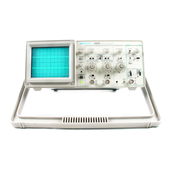
2205 Service LIST OF ILLUSTRATIONS Figure Page The 2205 Oscilloscope viii Maximum input voltage vs frequency derating curve for CH 1 X, CH 2 Y, and EXT INPUT Z conn ecto rs....................Instrument dimensional d ra w in g ................ -
Page 11: List Of Tables
2205 Service LIST OF TABLES Table Page Electrical Characteristics ......... . Environmental C haracteristics......................... Mechanical Characteristics ......Test Equipment Required , ....Deflection Accuracy Limits ......................7 .. 4-4 Settings for Timing Accuracy Checks ...... -
Page 12: Operators Safety Summary
2205 Service OPERATORS SAFETY SUMMARY The general safety information in this part of the summary is for both operating and service personnel. Specific warnings and cautions will be found throughout the manual where they apply and do not appear fn this summary. -
Page 13: Servicing Safety Summary
2205 Service SERVICING SAFETY SUMMARY FOR QUALIFIED SERVICE PERSONNEL ONLY Refer also to the preceding Operators Safety Summary Disconnect power before removing protective Do Not Service Alone panels, soldering, o r replacing components. Do not perform internal service or adjustment of this product unless another person capable of rendering first aid and resuscitation is present. - Page 14 6716-01...
-
Page 15: Specification
INTRODUCTION ACCESSORIES The instrument is shipped with the following accessories: The TEKTRONIX 2205 Oscilloscope is a rugged, lightweight, dual-channel, 20 MHz instrument that 1 Operators Manual features a bright, sharply defined trace on an 80 by 2 IX Signal Adapters 100 mm cathode-ray tube (c rt). - Page 16 Specification—2205 Service Table 1-1 Electrical Characteristics Characteristics Performance Requirem ents VERTICAL DEFLECTION SYSTEM Deflection Factor Range 5 mV per division to 5 V per division in a 1-2-5 sequence of 9 steps. Accuracy +15°C to +3S°C ±3%. 0°C to +15°C and ±5%.
- Page 17 Specification—2205 Service Table 1-1 (cont) C haracteristics Perform ance R equirem ents sssssssssassaam asam s TRIGGER SYSTEM Trigger Sensitivity P-P AUTO/TV LINE and NORM Modes S MHz 30 MHz Internal Signal 0.3 div 1.0 div External Signal 40 mV 150 mV Lowest Usable Frequency in >...
- Page 18 Specification—2205 Service Table 1-1 (cent) Characteristics Performance Requirements HORIZONTAL DEFLECTION SYSTEM (cent) Variable Control Range Continuously variable and uncalibrated between calibrated step settings. Decreases calibrated sweep speeds at least by a factor of 2-5. Sweep Linearity M agnified ■ ±7% ±5%...
- Page 19 Specification—2205 Service Table 1-1 (cont) Characteristics Performance Requirements POWER REQUIREMENTS Line Voltage Ranges 115V Setting 95 Vac to 128 Vac.® 230 V Setting 185 Vac to 150 Vac.® Line Frequency 48 Hz to 440 Hz. a Maximum Power Consumption 40 W (60 VA). a Line Fuse UL 198.6 3AG (1/4 X 1 1/4 inch)
- Page 20 S pecification—2205 Service Table 1-2 Environm ental Characteristics Performance Requirements Characteristics Temperature Operating 0°C to +40°C (+32°F to +104 °F). Nonoperating -5 5 °C to +75°C (~67°F to +167°F). Tested to MIL-T-28800C, paragraphs 4.5.5.1.3 and 4.5.5.1.4, except in 4.5.5.1.3 steps 4 and 5 (0°C operating test) are performed ahead of step 2 (-5 5 °C nonoperating test}.
- Page 21 Specification—2205 Service Table 1-3 Mechanical Characteristics Description Characteristics Weight with Power Cord 6.7 kg (14.8 lbs) or less. Domestic Shipping Weight 9.1 kg (20.1 lbs) or less. Dimensions 138 mm (5.4 in). Height Width 380 mm (15.0 in ). With Handle 327 mm (12.9 in).
- Page 22 Specification—2205 Service 6718-03 Figure 1-2. Instrument dimensional drawing.
-
Page 23: Operating Information
The ground contact on the plug connects through The 2205 operates from either a 115-V or a the power-cord to the external metal parts of the 230-V nominal ac power fine with any frequency instrument. - Page 24 □ z> > U J Ui W ■gg«0: TEKTRONIX INC . BEAVERTON. OREGON U S A MADE IN HONG KONG FLAT WASHER1 SELF-TAPPING SCREW W 1 6 -0 4 Figure 2-1. Voltage Selector switch, fuse, power-cord receptacle, and plastic clamp.
-
Page 25: And Indicators
Operating Inform atio n—2205 Service CONTROLS, CONNECTORS, AND INDICATORS The following descriptions are intended to fa CH 1—Selects only the Channel 1 input sig nal for display. miliarize the operator with the location and function of the instrum ent’s controls, connectors, BOTH—Selects a combination of Channel 1... - Page 26 Operating information—2205 Service Tfekhonix 2205 20M Hz OSCILLOSCOPE ^ h o riz o n ta l «^.f®s#»;TRiGGER f-zmm. IN T iN S IT Y , .Q. POSITION 6716-OS Figure 2-2. Front panel controls, connectors, and indicators. (T5) Variable VOLTS/DIV Controls—Provide con...
-
Page 27: Horizontal
Operating Inform ation—2205 Service (l5 ) CH 1 X and CH 2 Y Input Connectors— (23) LEVEL Control—Selects the amplitude point Provide for application of signals to the inputs on the trigger signal that produces triggering. of the deflection systems. -
Page 28: Rear Panel
Operating Information—2205 Service (30) Detachable-Power-Cord Receptacle—Pro- GH 2— Trigger signal is obtained from the v- '/ vldes the connection point for the ac-power CH 2 DR Y input. The CH 2 INVERT switch source to the instrument. also inverts the polarity of the internal Channel 2 trigger signal when the Channel 2 display is inverted. -
Page 29: Operating Considerations
Signal Adapter The signal adapter supplied with the instrument is GRATICULE usually the most convenient way to connect a signal to the 2205. These signal adapters are shielded to graticule internally marked on the prevent pickup of electromagnetic interference. -
Page 30: Operator's Checks And Adjustments
Operating Information—2205 Service Probe Handling (Optional Probes) Coaxial Cables maintain good waveform fidelity Both the probe and the probe accessories should accuracy, use only high-quality, low-loss coaxial be handled carefully to prevent damage. Striking a cables. When you use 50 D. or 75 n coaxial cable, attach a matching external term inator. -
Page 31: Probe Compensation (Option 10X Probe)
Operating inform ation—2205 Service 5. Check the waveform display for overshoot and 2. Use the CH 1 POSITION control to move the rounding (see Figure 2 -5 ): if necessary adjust baseline trace to the center horizontal graticule probe’s compensation. -
Page 33: Theory Of Operation
Si«e W O T S H U ■ In the following functional description of the 2205 connector. This precharging prevents large trace Oscilloscope, refer to the block diagram (Figure shifts of the display when switching from GND to AC 9-4) located in the Diagrams section of this manual. - Page 34 Theory of Operation—2205 Service Final amplification of the vertical signal is done by Output Amplifier to drive the crt horizontal deflection the Vertical Output Amplifier. This stage produces plates. the signal levels that vertically deflect the crt elec tron beam. For locating the position of off-screen...
-
Page 35: Detailed Circuit Description
Theory of Operation—2205 Service DETAILED CIRCUIT DESCRIPTION coupling, the Channel 1 signal goes directly to the VERTICAL input of the High-Impedance Attenuator stage. When ac coupled, the ac portion of the Input signal Attenuators passes through the dc-blocking capacitor C2. The... - Page 36 Theory of Operation— -2205 Service switch S90 is in NORM, the transistor pairs in U80 are Source Follower biased as they are in U30, and CH 2 trace is not inverted. In CH 2 INVERT position, connections to The Channel 1 signal from the input attenuator is...
- Page 37 Theory of Operation—2205 Service resistor R538. The outputs of U540A are then Q LO Channel Switch Logic and <3 HI enabling the Channel 2 Preamplifier signal Channel Switch circuitry, shown to drive the Vertical Output Amplifier, while the CH 1 Diagram 2, uses the front-panel VERTICAL MODE Preamplifier is disabled.
-
Page 38: Trigger Amplifiers And Switching
Theory of Operation— -2205 Service Coupling capacitor C547 and resistors R547 and and at high frequencies, the signal is coupled through C232 to the base of Q236. This provides R548 form a differentiating circuit that produces positive-going and negative-going short duration additional pull-up output current to drive the crt at pulses. - Page 39 Theory of Operation—2205 Service Internal Trigger Amplifier to produce the internal CR349 to prevent external trigger signals or the line trigger signal. trigger signal from reaching the Trigger Generator. Signals from the Internal Trigger Amplifier are CHOP VERTICAL MODE position,...
-
Page 40: Trigger Generator
Theory of Operation—2205 Service When the SOURCE switch is set to EXT=Z Trigger Level Comparator position, the external signal is buffered by Q370 and The Trigger Level Comparator compares signals applied Z-Axis amplifier intensity selected by the TRIGGER SOURCE switch to a modulation. -
Page 41: Sweep Generator And Logic
Theory of Operation—2205 Service Miller Sweep Generator TV video information and average the TV horizontai- sync pulses. Setting the trigger-level threshold near The Miller Sweep Generator produces a linear the center of the horizontal-sync-pulse swing es voltage ramp that drives the Horizontal Amplifier. It tablishes the untriggered level. - Page 42 Theory of Operation—2205 Service inverter U520A. The inverted signal of U520A is The sweep ramp starts when Q536 is biased off. applied to the input of U520B. The signal from U520B The GATE signal going to the base of Q701 from the is inverted by U520C to produce an OR function, Sweep Logic circuit turns Q7Q1 off.
-
Page 43: Horizontal
Theory of Operation—2205 Service U500A has timed out), U500B will clock a LO back X-Y Amplifier opto the Q output of U540B, allowing the TRIG'D/ READY LED to be extinguished. In the X-Y mode of operation, the 7 ? signal (buffered by Q736) is low, biasing Q732 in the linear X-Y. - Page 44 Theory of Operation—2205 Service voltage of the two shunt-feedback amplifiers to be The preamplifier is a cascode differential pair. The gain is set by the network connected between shifted positively to reduce the available voltage swing at the crt plates. This prevents the trace from pins 7 of U755C and 10 of U755D.
-
Page 45: Z-Axis Amplifier
Theory of O peration—2205 Service of Q829 rises to the blanking level. When blanked, Ac drive to the DC Restorer circuit is obtained from pin 3 of T902. The drive voltage has an ac peak the output of the Z-Axis Amplifier drops to reduce the crt beam current below viewing intensity. -
Page 46: Power Supply And Probe Adjust
Theory of Operation—2205 Service Focus Circuit The DC Restorer is referenced to the -1 .8 kV crt cathode voltage through R858 and CR854. Initially, Focus voltage is developed from the -1 .8 kV both 0855 and 0854 charge up to a level de... - Page 47 Theory of Operation—2205 Service 6716-12 Figure 3-6. Block diagram of the Power Supply. After the initial Startup, current passed by Q982 is applied to one end of 1950 via Q933. The other end applied through CR980 via R971 and R980 instead of of L950 is held to 20 V by the capacitive load that is C982.
- Page 48 Theory of Operation—2205 Service charged to the 60 V supply, the source-gate voltage generator U930. This will hold the output of U930 in a low state and keep Q933 turned on. The load current of Q933 is 0 V, turning it off.
- Page 49 Theory of Operation—2205 Service CR986, CR987, CR988, and CR989 produces the Line Signal 8,6 V and -8.6 V. Filtering of the 8.6 V is done by Transistor Q900 is a floating differential amplifier C986, C987 and L986; filtering of the -8.6 V is done by C988.
-
Page 51: Introduction
Section 4—2205 Service PERFORMANCE CHECK PROCEDURE INTRODUCTION section and the Adjustment Procedure in Section 5. PURPOSE Test equipment specifications described Table 4-1 are the minimum necessary to provide The Performance Check Procedure is used to accurate results. Therefore, equipment used must verify the instrument's Performance Requirements meet or exceed the listed specifications. - Page 52 Performance Check Procedure—2205 Service ■ ' ■ Table 4-1 Test Equipment Required Example of Suitable Item and Minimum Specification Test Equipment Description Purpose Signal source for gain TEKTRONIX PG 506 1. Calibration Standard-amplitude signal (evils: Calibration Generator.8 Generator 5 mV to 50 V. Accuracy: +0.3%.
-
Page 53: Index To Performance Check Steps
Perform ance Cheek Procedure—2205 Service Check Variable Range......... 4-7 INDEX TO PERFORMANCE CHECK STEPS 4. Check X G ain......5. Check X Bandwidth........4-7 Vertical Page Trigger 1. Check Deflection Accuracy and !..1 Variable Range Check Internal Triggering ......2. Check Bandwidth...., .. -
Page 54: Vertical
Performance Check Procedure—2205 Service VERTICAL Equipment Required (See Table 4-1): Calibration Generator (Item 1) Dual-Input Coupler (Item 7) 5 0 - fl Termination (Item 8) Leveled Sine-Wave Generator (Item 2) 5 0 - fl Coaxial Cable (Item 6) INITIAL CONTROL SETTINGS the CH 1 VOLTS/DIV Variable control to the CAL detent and continue with the 50-mV check. -
Page 55: Check Channel Isolation
Performance Check Procedure—2205 Service b. Connect the leveled sine-wave generator out Move the test-signal cable from the CH 2 put via a 5 0 -0 coaxial cable and a 5 0 -0 termination input connector to the input connector. to the CH 2 V input connector. -
Page 56: Horizontal
Performance Check Procedure—2205 Service HORIZONTAL Equipment Required (See Table 4-1): Calibration Generator (Item 1) 50- a Coaxial Cable (Item 6) Leveled Sine-Wave Generator (Item 2) 50- f l Termination (Item 8) Time-Mark Generator (item 3) CHECK—Timing accuracy is within 3% (0.24... -
Page 57: Check Position Range
Performance Check Procedure—2205 Service b. Select 0.1 ms time markers from the tim e- i. CHECK—Timing accuracy is within 4% (0.32 mark generator. division at the tenth vertical graticule line), and linearity is within 7% (0.14 division over any 2 of the c. -
Page 58: Check X Bandwidth
Performance Check Procedure-2205 Service CHECK—The display is between 4.85 and 5.15 b. Connect the leveled sine-wave generator out divisions. put via a 5 0 -ft coaxial cable and a 50-X1 termination to the CH 1 OR X input connector. Disconnect the test equipment from the c. -
Page 59: Trigger
Performance Check Procedure—2205 Service TRIGGER Equipment Required (See Table 4-1): Dual-Input Coupler (Itehrt T) Leveled Sine-Wave Generator (item 2) 50-D Coaxial Cable (Item 6) 5 0 -n Termination (Item 8) combination given in Table 4-4. Ensure that the INITIAL CONTROL SETTINGS TRIG'D light comes on when triggered. -
Page 60: Check External Triggering
Performance Check Procedure—2205 Service 2. Check External Triggering d. Set: Trigger MODE NORM Trigger SOURCE EXT, EXT CH 1 VOLTS/DIV 20 mV e. CHECK—Display is triggered along the entire SEC/DIV 0.2 ms positive slope of the waveform as the Trigger LEVEL Horizontal MODE control is rotated. - Page 61 Performance Check Procedure—2205 Service CHECK-TRIG’D/READY LED goes out and a i. CHECK—A single-sweep trace occurs, and single sweep occurs. the TRIG‘ D/READY LEO illuminates briefly every time the SGL SWP RESET button is pressed. j. Disconnect the test equipment from the Press the SGL SWP RESET button several times.
-
Page 62: External Z-Axis And Probe Adjust
Performance Check Procedure—2205 Service EXTERNAL Z-AXIS AND PROBE ADJUST Equipment Required (See Table 4 -1 ): Calibration Generator (Item 2) 5 0 -n Termination (Item 8) Two 50-X1 Coaxial Cable (Item 6) 10X Probe (Item 12) Dual-Input Coupler (Item 7) -
Page 63: Introduction
Section 5—2205 Service ADJUSTMENT PROCEDURE INTRODUCTION use of equipment other than that recommended, PURPOSE utilize the Minimum Specification column to deter mine whether available test equipment will suffice. The Adjustment Procedure is used to return the instrument to conformance with the Performance Requirement statements listed in Table 1-1. - Page 64 Adjustment Procedure-2205 Service All test equipment items listed in Table 4-1 in the readjustment of the instrument, whereas only a par Performance Check Procedure section are required tial adjustment migfit othiriwise be required. Only to accomplish a complete Adjustment Procedure. At...
-
Page 65: Index To Adjustment Procedure Steps
Adjustment Procedure—2205 Service 15. Check Common-Mode Rejection Ratio .. 5-10 INDEX TO ADJUSTMENT PROCEDURE STEPS Horizontal Power Supply and CRT Display Page 1. Adjust 1-ms Tim ing........5-11 2. Adjust Magnifier Gain ..; ....5-11 1. -
Page 66: Power Supply And Crt Display
Adjustment Procedure—2205 Service POWER SUPPLY AND CRT DISPLAY Equipment Required (See Table 4-1): 50- f t Coaxial Cable (Item 6) Leveled Sine-Wave Generator (item 2) 50- f t Termination (Item 8) Time-Mark Generator (llsrn 3) Alignment Tool (Item 11) Digital Voltmeter (Item 5) ■'AOJUSTMI^... -
Page 67: Adjust Astigmatism
Adjustment Procedure—2205 Service Rotate INTENSITY control fully 5. Adjust Geometry (R871) counterclockwise. a. Set: c. ADJUST—Grid Bias (R851) for a visible dot, then back off the Grid Bias potentiometer until the CH 1 VOLTS/DIV 50 mV dot just disappears. SEC/DIV 0.1 ms... -
Page 68: Vertical
Adjustment Procedure—2205 Service VERTICAL Equipment Required (See Table 4-1): Calibration Generator (Item 1) 10X Attenuator (Item 9) Leveled Sine-Wave Generator (Item 2) Miniature Probe Tip to BNC Adapter (Item 10) 5 0 -f l Coaxial Cable (Item 6) Alignment Tool (Item 11) -
Page 69: Adjust Channel 2 Invert Balance
Adjustment Procedure—2205 Service rotate the CH 1 VOLTS/DIV Variable control fully Return the CH 1 VOLTS/DIV Variable control to counterclockwise and CHECK that the display the CAL detent decreases to two divisions or less. Then return the CH 1 VOLTS/DIV Variable control to the CAL detent Adjust Channel 2 Invert Balance (R84) and continue with the 50-mV check. -
Page 70: Check Position Range
Adjustment Procedure—2205 Service i. Set the Vertical MODE switch to CH 1. d. Replace the probe and miniature probe tip to BNC adapter with a 5 0 -fl coaxial cable and 5 0 -0 termination. j. Repeat parts b through g using the Channel 1 controls. -
Page 71: Adjust Chop Switch B A La N Ce
Adjustment Procedure—2205 Service I. Set the CH 2 VOLTS/DIV switch to 50 mV. 11, Check ADD MODE Operation m. Repeat parts d through i except adjust the “ 3 a. Set: and “ 3N" trimmers in parts f and i respectively. -
Page 72: Check Bandwidth
Adjustment Procedure—2205 Service f. ADJUST-HF Comp (C241 and R241) for best f. Repeat parts c through e for all CH 1 VOLTS/ flat top on the front corner. DIV switch settings, up to the output-voltage upper limit of the sine-wave generator being used. - Page 73 Adjustment Procedure—2205 Service c. Set the generator to produce a IG-MHz, Disconnect the test equipment from the 6-division display. instrument. NOTE Set Vertical MODE switch to CH 2 INV and ADD. To continue with the "Adjustment Pro- cedure” , remove the instrument cabinet and allow a 20-minute warm-up period.
-
Page 74: Horizontal
Adjustment Procedure—2205 Service HORIZONTAL Equipment Required (See Table 4-1): Calibration Generator (Item 1) 5 0 - fl Coaxial Cable (Item 6) Leveled Sine-Wave Generator (Item 2) 5 0 - fl Termination (Item 8) Time-Mark Generator (item 3) Alignment Tool (Item 11) -
Page 75: Check Position Range
Adjustment Procedure—2205 Service 6. Adjust 0.1-m s and 0,1- jis Tim ing (R722 and f. Set the MAG switch from XI to X I0 position and CHECK for no Horizontal shift in the time C703) marker.. a. Set the SEC/DIV switch to 0.1 ms. - Page 76 Adjust merit Pro cedu re—2205 Service d. Use the Horizontal POSITION control to align Table 5-4 the second time marker with the second vertical Settings fo r Timing Accuracy Checks graticule line. e. CHECK—Timing accuracy is within 3% (0.24 SEC/DIV...
-
Page 77: Check X Bandwidth
Adjustment Procedure—2205 Service Position the trace horizontally so the start of 11. Check Sweep Holdoff the trace begins at the first vertical graticule line (ex treme left). a- Set: VOLTS/DIV (both) Set the SEC/DIV switch (fully AC-GND-DC (both) counterclockwise). SEC/DIV... -
Page 78: Trigger
Adjustment Procedure—2205 Service TRIGGER Equipment Required (See Table 4-1): 5 0 -0 Termination (Item 8) Leveled Sine-Wave Generator (Item 2) Alignment Too! (Item 11) 5 0 - 0 Coaxial Cale (Item 6) Dual-Input Coupler (Item 7) ADJUSTMENT LOCATIONS 1 at the back of this manual for adjustment locations. -
Page 79: Adjust Slope Balance
Adjustment Procedure—2205 Service d. Set the CH 1 VOLTS/DIV switch to 1 V. ■bi Set the generator to produce a 5-MHz, 3-division display. e. ADJUST— Trig Sensitivity (R489) while rotating c. Set the GH 1 VOLTS/DIV switch to 50 mV. -
Page 80: Check External Trigger Range
Adjustment Procedure—2205 Service dual-input coupler to the CH X input con CHECK—Display is triggered along the entire nector and EXT INPUT 2 input connectors. negative slope of the waveform as the Trigger LEVEL control is rotated. c. Set the generator to produce a 4-division (80 mV) horizontal display at an output frequency of CHECK—Display is not triggered at either... -
Page 81: External Z-Axis And Probe Adjust
Adjustment Procedure—2205 Service EXTERNAL Z-AXIS AND PROBE ADJUST Equipment Required (See Table 4-1): 5 0 -fi Termination (Item 8) Calibration Generator (Item 1) 10X Probe (Item 12) Two 5 0 -fl Coaxial Cables (Item 6) Dual-Input Coupler (Item 7) NOTE... -
Page 83: Maintenance
Section 6—2205 Service MAINTENANCE This section contains information for conducting board removal procedures are included in the Cor- preventive maintenance, troubleshooting, and cor- rective Maintenance part of this section, rective maintenance on the instrument. Circuit STATIC-SENSITIVE COMPONENTS The following precautions are applicable when... -
Page 84: Preventive Maintenance
99% water. Before using any other type of cleaner, consult your A plastic light filter is provided with the oscil Tektronix Service Center or representative. loscope. Clean the light filter and the crt face with a soft lint-free cloth dampened with either isopropyl alcohol or a mild detergent-and-water solution. - Page 85 Maintenance—2205 Service Table 6-2 External Inspection Checklist Item Inspect For Repair Action Touch up paint scratches and Cabinet and Front Panel Cracks, scratches, deformations, replace defective parts. and damaged hardware or gaskets. Repair or replace missing or Front-panel controls Missing, damaged, or loose knobs, defective items.
-
Page 86: Lubrication
M aintenance-2205 Service Table 6-3 internal Inspection Checklist Repair Action Inspect For Item Clean solder corrosion with an Loose, broken, or corroded solder Circuit Boards eraser and flush with isopropyl connections. Burned circuit boards. alcohol. Resolder defective con Burned, broken, or cracked circuit-run plating. -
Page 87: Troubleshooting
Maintenance—2205 Service TROUBLESHOOTING The locations of waveform test points are marked INTRODUCTION on the circuit board illustrations with hexagonal outlined numbers corresponding to the waveform Preventive maintenance performed on a regular numbers on both the schematic diagram and the basis should reveal most potential problems before waveform illustrations. -
Page 88: Troubleshooting Equipment
Operating Information with a series of stripes, the color combination of the in Section 2 of this manual or to the Operators stripes identifies three digits of the Tektronix Part Manual. Number, using the resistor color-code system. The... - Page 89 Maintenance-2205 Service 2. Check Associated Equipment 5. Isolate Trouble to a Circuit To isolate problems to a particular area, use any Before proceeding, ensure that any equipment symptoms noticed to help locate the trouble. Refer used with the instrument is operating correctly.
- Page 90 M aintenance-2205 Service 7. Check Circuit Board Interconnections See Figure 9-1 for component value identification Figure semiconductor lead configurations. After the trouble has been isolated to a particular circuit, again check for loose or broken con nections, improperly seated semiconductors, and heat-damaged components.
- Page 91 Maintenance—2205 Service resistance between terminals with an ohmmeter set CAUTION to a range having a low internal source current, such as the R X 1 -k fl range. The diode resistance should be very high in one direction and much lower when When checking emitter-to-base junctions, do the meter leads are reversed.
-
Page 92: Corrective Maintenance
(cross Tektronix, Inc., be sure to include all of the following grounding). information: 1. Instrument type (include all modification and 4. When soldering on circuit boards or small option numbers). -
Page 93: Ribbon-Cable Connections
Maintenance—2205 Service Table 6-5 Maintenance Aids Description Usage Specification Example 1. Soldering Iron Antex Precision 15 to 25 W. General soldering Model C. and unsoldering. 2. Torx Screwdriver Torx tips #T9 and Tektronix p/n Assembly and # f is . -
Page 94: Transistors And Integrated Circuits
Use rosin-core wire solder containing 63% tin conductor devices may affect the adjustment of the and 37% lead. Contact your local Tektronix Field instrument. When a semiconductor is replaced, Office or representative to obtain the names of check the performance of any circuit that may be approved solder types. -
Page 95: Removal And Replacement Instructions
Maintenance—2205 Service Attempts to unsolder, remove, and resolder Do not move the component while the solder leads from the component side of a circuit board hardens. may cause damage to the reverse side of the circuit board. 6. Cut off any excess lead protruding through the circuit board (if not clipped to the correct length in step 3). - Page 96 Maintenance—2205 Service Pull the front panel and attached chassis NOTE forward and out of the cabinet. When installing the ert into the instrument, reinstall any loose plastic ert corner pads that 7. To reinstall the cabinet, perform the reverse of the preceding steps.
- Page 97 Maintenance—2205 Service Mains Input Circuit Board 2. Place the instrument down (normal position) and use a 1/16-inch hex wrench to loosen the set screws on the CH 1 VOLTS/DIV, CH 2 VOLTS/DIV, The Mains Input circuit board can be removed and SEC/DIV Variable knobs.
- Page 98 Maintenance—2205 Service 8. Remove one screw from the center front 7. Remove the five screws that secure the bottom of the attenuator shield. Front-Panel circuit board to the front chassis, noting their respective positions. 9. Remove two screws from the front corners of 8.
- Page 99 Maintenance—2205 Service 7. Rotate the instrument until the rear chassis is 15. Remove three screws and nuts that secure facing you. the Main circuit board to the right side of the chassis frame. 8. Remove the two screws (lower right corner) that secure the heat sink for the vertical output tran...
-
Page 101: Options And Accessories
OPTION 1C OPTION 22 When Option 22 is specified, 24 IX Signal When Option 1C is specified, a Tektronix C-5c Option 04 low-cost camera is included in the ship Adapters are included with the instrument. Each cable has one BNC Male connector on one end and ment. -
Page 102: Option 23
INTERNATIONAL POWER CORDS Instruments are shipped with the detachable When Option 23 is specified, two P6103 10X power cord and fuse configuration ordered by the Probes are included with the instrument. customer. Table 7-1 identifies the Tektronix part numbers international power cords associated fuses. - Page 103 Options Description—2205 Service Table 7-2 Optional Accessories Description Part Number Front Panel Protective Cover 200-3397-00 Accessory Pouch 016-0677-02 Front Panel Protective Cover 020-1514-00 and Accessory Pouch Transit Case 016-0792-01 CRT Light Filter, Clear 337-2775-01 Rack Mount Conversion Kit 016-0819-00 Viewing Roods...
-
Page 104: Standard Accessories
Options Description-2205 Service Table 7-2 (cont) Description Part Number Portable Power Supply 1105 Battery Pack 1106 Oscilloscope Cameras C-5C Option 04 Low-cost Motorized C-7 Option 03 and Option 30 Portable Instrument Cart K212 2205 Service Manual 070-6716-00 STANDARD ACCESSORIES Each instrument is shipped with the following standard accessories. -
Page 105: Replaceable Electrical Parts
If a pan you have ordered has been replaced w ith a new or assemblies and parts) improved part, your local Tektronix, I nc F ield O ffice o r represen tative w ill contact you concerning any change in part number. - Page 106 Replaceable E le c tric a l Parts - 2205 S ervice CROSS INDEX - MFR. CODE NUMBER TO MANUFACTURER H fr. Code Manufacturer Addhess C ity . State. Zip Code 00213 NYTRQNICS C O M PO N EN TS G R O U P INC...
- Page 107 Replaceable E le c tric a l P arts - 2205 S ervice CROSS INDEX - MFR. CODE NUMBER TO MANUFACTURER H fr. Manufacturer ; Address Code C ity, State. Zio Code K7779 SI E K E S K S LTD...
- Page 108 Replaceable E le c tric a l P arts - 2205 Service Tektronix Serial/Assaribly No. M fr. Catponerrt Ito. Part Ito. E ffective Dscont________ Name & Description______________________Code M fr. Part No. 671-0425-00 CIRCUIT BD ASSY:MAIN 80009 671-0425-00 671-0390-00 CIRCUIT 80 ASSY:TIf€BASE/ATTEN...
- Page 109 Replaceable E le c tric a l P arts - 2205 Service Tektronix Serial/Assembly No. H fr, Ccnoanent No. Effective Oscorrt K fr. Part to . .'Part. Me,. tone & Description Code 671-0425-00 80009 CIRCUIT B D ASSY:MAIN 671-0425-00 A1C114...
- Page 110 Replaceable E le c tric a l P arts - 2205 Service Tektronix Serial/Asserably (to. Hft-., CtBComait Ho. Part fa . E ffective Psccnt Haas & Description rnrfc. M fr. Part Mo. A1C537 281-0775-01 CAP.fXD.CER 01:0.1UF,2Q%,50V 04222 SA1Q5E104MAA A1C538 281-0812-00 CAP.fXD.CER D1:1000PF,10%.100V...
- Page 111 Replaceable E le c tric a l P arts - 2205 S ervice Mfr, Serial/Assembly No. Tektronix Effective Oscont Kane ft Description Code M fr. Part No. Corocnent No..Part No- CAP, fXD,MTL2D:0.01 UF,20%,4000V 56289 430P591 285-1184-00 A1C976 CAP,FXD.MTLZD:0.01 UF,20%,4000V...
- Page 112 >* 3* 3> 3> 1> 3> a> 3> 3> 3> 3» 3* > 3* >- 3» 3* 3» 3> 3* 3» >■ s e e e s s J - * * - * » - * £ - f - » ♦ — ftm * }w «...
- Page 113 JS S 5 S S S > » > > > P S 7 2 f* ■ * ” * * “• l— gfS&fSfjSB “ ~ ^ g g J O b Q a § i § s I o ' o o o o o &...
- Page 114 Replaceable E le c tric a l P arts - 2205 S ervice Tektronix S erial/A ssaitily Ho. M fr. Comcnentlto. Part Cads M fr. Part No. E ffective Dscont Dane & Description A1Q370 80009 151-1042-00 151-1042-00 SEMIC0ND SE:FET.SI,T0-92 ------* * ------...
- Page 115 Replaceable E le c tric a l Parts - 2205 S ervice Tektronix Serial/Assestoly No. H fr. Part Ho. E ffective Dscorrt M fr. Part Ho. Cods A1R118 315-Q8Z1-O0 RES,FXD,FILM:820 OHM,5%,0.25W 19701 5043CX820ROJ A1R119 RES,FXD.FILM:820 0W.5%.0,25W 315-0821-00 19701 5043CX820ROJ airi RES,FXD,FILM: 187 0HM,1X,0.125W, TWO...
- Page 116 Replaceable E le c tric a l P arts - 2205 S ervice M fr. Tektronix S erial/A sseitly No. Caicicnent No. Code M fr. Part No. Part (to. E ffective Oscont Name & Description A1R204 RES, FXO,FILM:82.5 0HM,1%0.125W,TC=T0 CMF55116G82R50F...
- Page 117 Replaceable E le c tric a l Parts - 2205 S ervice Tektronix Serial/Assembly No. M fr. Comment No. Part No. E ffective Dscont M fr. Part No. tone & Oescriotion Cede 321-0098-00 A1R316 RES.FXO.FILM:102 OHM. 1%,0.1294.TC=T0 CEAD102ROF 07716 315-0241-00 A1R317 R£S,FXD,FILM:240 0HH.5X.0.2SW...
- Page 118 Replaceable E le c tric a l P arts - 2205 S ervice Tektronix Serial/Assembly No. Mfr. ConDcneirt No. Part No. Cods M fr. Part No. Effective Oscorrt Name & Description A1R406 RES.FXO,FILN:2K QHM,5%,0.25U 57668 NTR25J-E 2K 315-0202*00 NTR25JE01K0 A1R407...
- Page 119 Replaceable E le c tric a l Parts - 2205 S ervice Tektronix Serial/Assertdy No. Mfr, Coroonent No. Part No. Effective Decent Nam e & Description Cede M fr. Part No. NTR2SJ-E09K1 AIRS18 315-0912-00 RES,FXD,FILM:9 .IK 0HM,5X,0.25W 57668 A1R520 315-0102-00 RES,FXD,FILM:IK 0H15X,0.25W...
- Page 120 * s r & JS 2 &SS S?w » ™ *'*« "* )iitf. .k H * Ife *. U > + m k m s s U > b ) U » t i l ‘TV'Y'SmJS ftd r«» »-• * ■ — hr* b«* PO h r* h->...
- Page 121 & > £ £ 73 70 S £ 2 g S g § § 2 3 5 Z] s! S ''4 ( § g s f f « £ £ > S g p £ £ £ > > 3* £...
- Page 122 Replaceable E le c tric a l P arts - 2205 Service Tektronix Serial/Assembly No. M fr. Conxment No. Part No. Effective Dscont Ita e & Description Code M fr. Part No. A1R888 301-0514-00 RES, FXO, FILM:510K OW.SX.O.SW 19701 5053CX510K0J...
- Page 123 Replaceable E le c tric a l F a rts - 2205 S ervice Tektronix Serial/Assembly No. M fr. Comment No. Part No. E ffective Dscont Name I Descrintion Cade M fr. Part Ho. A1R985 315-0303-00 RES, FXD,FIlN:3fflC 0HM,5X,0.25W 19701...
- Page 124 Replaceable E le c tric a l Parts - 2205 S ervice Tektronix Serial/Assembly Ho. H fr. Comment No. Part Ito. Effective Dscont Nans & Description Code. . H fr. P art Ito A1W921 131-0566-00 D M A 07 8US,eQlfflUCTOR;0UW RES,0.094 OD X 0,225 L...
- Page 125 Replaceable E le c tric a l P a rts - 2205 S ervice Tektronix Serial/Assertbly No. M fr: fjifc M r . Part No. Part No. E ffective Qscorrt Naae b Descriotion ' Ccnxnent No. 671-0390-00 671-0380-00 CIRCUIT 80 ASSY:TIM£8ASE/ATTEN 80009 SWITCH,R0TARY:1M 0HM.10 P Q S ATTENUATOR...
- Page 126 Replaceable E le c tric a l P arts - ® g S ervice Tektronix Senal/Assenbly No. H fr. pyftt Part No. E ffeetivs fecorrt Coeoonent (to. NaK & iOeBcriDticn M fr. Part Ito. 151-1054-00 A2Q53 151-1054-00 TIM^ISTOR:flT>N-CHAN,SI,T0-71 80009 A2Q64...
- Page 127 Replaceable E le c tric a l P arts - 2205 S ervice . . . Tektronix Serial/Assenfcly No. BIT- Caipanent Mo. Part No. E ffective Dscont Ifeme A Description M fr. Part No. Coda A2R715 321-0231-00 RES,FXD, FILM:2.49K OWUX.O. 125W,TC=T0...
- Page 128 Replaceable E le c tric a l Parts - 2205 S ervice Tektronix Serial /ftssartjly to . K fr. Component Bo. Part Wo._____ E ffective Dscont Hare & Description Coda H fr. Part Mb. A2W742 131-0566-00 BUS.COIffiUCTOR:D U M M Y RES.O 094 0D X 0.225 L...
- Page 129 Replaceable E le c tric a l P arts - 2205 Service Tektronix Serial/Assertbly No. H fr. T/rfa Effective Qsccnt Part Mo. Mans 8 DeScriotion H fr. Part Mo. fem cnent Vo; 671-0392-00 CIRCUIT B O ASSY:FRONT PANEL 80009 671-0392-00 285-1106-00 CAP, FXD,PLASTIC:0.
- Page 130 Replaceable E le c tric a l P arts - 2205 S ervice Tektronix Serial/A sseibly No. H fr. CcBoanerrt No. Nane & Description Code : Part (to, E ffective Decent J f c J t o f t x ..
- Page 131 Replaceable E le c tric a l P arts - 2Z05 S ervice Tektronix Serial/Assatfcly No. M fr. Comxment No. Part No. E ffective Qscant None & Description Code M fr. Part No. m is FS9Q1 159-0042-00 RBE, CARTRIDGE :3AG, 0 .75A. 250V, 0 .15SEC 312.750...
- Page 133 2205 Service VERTICAL PREAMP & OUTPUT AM PLIFIER DIAGRAM 2 ASSEMBLY A1 cm curr SC H EM BOARD C IR C U IT S C H E M BOARD cm curr S C H EM BOARD S C H EM...
-
Page 134: Diagrams
2205 Service TRIG GER DIAGRAM 3 ASSEMBLY A1 CIRCUIT SCHEM BOAffl) CIRCUIT SCHEM BOARD CIRCUrT SCHEM BOARD CIRCUIT BOA] SCHEM LOCATION LOCATION NUMBER LOCATION LOCATION NUMBER NUMBER NUMBER LOCATION LOCATION LOCATION LOCAT C320 R3t» 8361 R495 C321 R304 8389 R496... - Page 135 2205 Service WAVEFORMS FOR DIAGRAM 4 <<s> AC Waveforms for 4E through 4N VOLTS/DIV 0.1 V AC-GND-DC SEC/DIV Input signal 4-division, 50 kHz reference sine wave S716-31...
-
Page 136: Section 10 Replaceable Mechanical Parts
Attaching p arts for D etail P art If a part you have ordered has been replaced with a new or improved part, your local Tektronix, inc. Field Office or EN D ATTACHING PA R TS representative will contact you concerning any change in part number. - Page 137 Replaceable Mechanical P arts - 2205 S ervice CROSS INDEX - MFR. CODE NUMBER TO MANUFACTURER M fr. Manufacturer Address C ity . State. Zip Code Code R O C K FO R D IL 61108 01536 TEXTRON INC 1818 CHRISTINA ST...
- Page 138 Replaceable Mechanical P arts - 2205 S ervice Fig. & Mfr. Index Tektronix Serial/A ssaibly No. Part No. E ffective Oscont 12345 Name & Description M fr. Part No. Code 426-1765-02 FRAME.CRT:P01YCARB0NATE,GRAY TK2165 ORDER BY DESCR ATTACHING PARTS 211-0690-01 SCREW,MACHINE:6-32 X 0.875 PNH.SST...
- Page 139 Replaceable Mechanical P arts - 2205 S ervice Fig. & Index Tektronix Serial /Assembly No. M fr. M fr. Part Mo. Piart No. E ffective..Decant.. 1Z345 Name & Oescriction Code 441-1752-01 TKDEO ORDER BY DESCR CHASSIS.SCOPI.’FRQNT ATTACHING PARTS 211-0718-00 83486 QHXR BY DESCR SCREW,MACHINE:6-32 X 0.312,FLH.lOO DEG,STL...
- Page 140 Replaceable Mechanical P arts - 2205 S ervice Fig. & M fr. Tektronix Serial/Aasanbly No. Index ' f^rip Part No. M fr. Part No. . E ffective Ascent 12345 Nawe 8 Descriotim t?ty 83385 ORDER BY DESCR 2-39 SCREW,MACHINE:8-32 X 2.825,HEX H),STL...
- Page 141 Replaceable Mechanical P arts - 2205 S ervice F ig . & M ir. Index Tektronix Serial/Assenbly No. H o . fa te M fr. Part No. Part ita. E ffective Oscont 12345 Name & Description S TA N Q A R D ACCESSORIES...
- Page 142 PIG. 3 ACCESSORIES Q >...
- Page 143 REVISION INFORMATION id v k i u riiJ v Manual Part No. 070-6716-00 First P rinting_ _ A M fJ jfM Revised P roduct:____2205 Service Manual Manual Insert Status DATE CHANGE REFERENCE STATUS MAY 8 1988 C1/0588 Effective FEB 15 1989 M67537 Effective FEB 20 1989...
- Page 144 _ Q -j com m itted to D o c a ju E N c s ? ~ 5~ aH_______ ci/pase_____ Date: Change Reference: Product: 2205 SERVICE Part ^ 070-6716-00 DESCRIPTION Product Group 46 EFFECTIVE ALL SERIAL NUMBERS DIAGRAM CHANGES DIAGRAM <...
- Page 145 M iw rrc o T o Date: 2-15-89 Chanoe Reference: M67537 ex c elle n c e Product- 2205 SERVICE Manual Part Number: 070-6716-00 DESCRIPTION Product Group SEE BELOW FOR EFFECTIVE SERIAL NUMBERS: REPLACEABLE ELECTRICAL PARTS LIST CHANGES...
- Page 146 MANUAL CHANGE INFORMATION Product: 2205 SERVICE Date: 2-15-89 Change Reference: M67537 DESCRIPTION Product Group DIAGRAM CHANGES (cont) DIAGRAM VERTICAL ATTENUATORS (cont) Page 2 o f 2...
- Page 147 MANUAL CHANGE INFORMATION T f e k t r o n i x 2-20-89 M67538 COMMnmED TO EXCELLENCE Date: Chanqe Reference: 2205 SERVICE Product- Manual Part Number: 070-6716-00 DESCRIPTION Product Group EFFECTIVE SERIAL NUMBER: HK 1 0 5 0 0...
- Page 149 MANUAL CHANGE INFORMATION COMMfTTSJTOEXCELlBVCE Date: 5 -2 -8 9 Change Reference: M681 TO______ Product: 2205 SERVICE Manual Part Number: 070-6716-00 _______________________________________ DESCRIPTION_____________________ Product Group EFFECTIVE SERIAL NUMBER: H K 11184 REPLACEABLE ELECTRICAL PARTS UST CHANGES (CHASSIS PA R TS )
- Page 151 C O M M ITtE D lO EXCELLENCE Date: 01-20-90 Change Reference: M67539______ Manual Part Number: 070^-6716-00 Product: 2205 SERVICE DESCRIPTION Product Group 46 EFFECTIVE SERIAL NUMBER: HK10500 REPLACEABLE ELECTRICAL PARTS LIST CHANGES C H A N G E TO : U940...
- Page 152 MANUAL CHANGE INFORMATION COMMITTED TO EXCELLENCE Date: 01-20-90 Change Reference: M67539_______ Product: 2205 SERVICE Manual Part Number: 070-6716-00 DESCRIPTION Product Group DIAGRAM CHANGES DIAGRAM < 6 > FRONTPANELCONTROLS Change the value of capacitor C378 (location 8H) to 330 pF. EFFECTIVE SERIAL NUMBER: HK11110...
- Page 153 MANUAL CHANGE INFORMATION COMMITTED TO EXCELLENCE Date: 01-20-90 Change Reference: M67539_______ Product: 2205 SERVICE____________________________________ Manual Part Number: 070-6716-00 DESCRIPTION Product Group 46 DIAGRAM CHANGES DIAGRAM ^ VERTICAL ATTENUATORS Orange the value and circuit number of L93 (location 7B) to R97 4.7...
- Page 155 MANUAL CHANGE INFORMATION COMMITTEDTO EXCELLENCE Date: 02-02-90 Change Reference: C1/0290_______ Product: 2205 SERVICE _________________ Manual Part Number: 070-6716-00 DESCRIPTION Product Group SEE BELOW FOR EFFECTIVE SERIAL NUMBERS Section 7 OPTIONS AND ACCESSORIES Page 7 -1 . Option Two P6119 1X-1 OX...
- Page 157 Ifektronix MANUAL CHANGE INFORMATION COMMITTED TO EXCELLENCE Date: 3-20-90 Change Reference: C2/0390_______ Product: 2205 OSCILLOSCOPE SERVICE _________________ Manual Part Number: 070-6716-00 DESCRIPTION Product Group EFFECTIVE SERIAL NUMBER: ALL TEXT CHANGES PAGE 1-4 CHANGE TO: Table 1 -1 (cont) Characteristics Performance Requirements...
- Page 159 Tektronix MANUAL CHANGE INFORMATION Date: 8-23-91 Change Reference: M73789fRevY committed to excellence Product: 2205 SERVICE MANUAL_____________ :■ 1 ■ . Manual Part Number: 070-6716-00 ______________________________ DESCRIPTION________________________ Product Group EFFECTIVE SERIAL NUMBER: HK54509 and HK12226 TEXT CHANGES Page 4 -2 Table 4 -1...
- Page 160 MANUAL CHANGE INFORMATION Product 2205 SERVICE Date: 8-23-91 Change Reference: M73789(RevY DESCRIPTION Product Group DIAGRAM CHANGES DIAGRAM POW ER SUPPLY Remove C932 (location 5E) and add A6 Frequency Stabili2ing Circuit Board to power supply: Connect J901 -1 to + hole where C932 was previously installed.
- Page 161 MANUAL CHANGE INFORMATION COMMOTED TO EXCELLENCE Date: 2 -5 -9 2 C3/0292 Change Reference:. Product: 2205 SERVICE MANUAL 0 7 0 -6 7 1 6 -0 0 Manual Part Number: DESCRIPTION Product Group 46 SEE BELOW FOR EFFECTIVE SERIAL NUMBERS...
- Page 162 MANUAL CHANGE INFORMATION Product: 2205 SERVICE MANUAL Date: 2 - 5 - 9 2 Change Reference. C3/0292 DESCRIPTION Product Group 46 Partial Figure 2 Exploded View Page 2 of 3...
- Page 163 MANUAL CHANGE INFORMATION Product: 2205 SERVICE MANUAL____________ Date: 2 - 5 - 9 2 Change Reference: C3/0292 _________________________ DESCRIPTION Product Group 46 DIAGRAM CHANGES Effective Ref, Sedai Number Number DIAGRAM w S VERTICAL PREAMP & O U TPU T A M PLIFIER Change the value of resistor R245 (location 3P) to 1.3 kQ.
- Page 165 MANUAL CHANGE INFORMATION COW^TTHJTOEffiaifNCE Date: 7 -2 3 -9 2 Change Reference: M77514_______ 2205 SERVICE MANUAL Product; _________________ Manual Part Number: 070-6716—00 DESCRIPTION Product Group 46 EFFECTIVE SERIAL NUMBER: HK10001 REPLACEABLE ELECTRICAL PARTS LIST CHANGES CHANG E TO: SLOW BLOW...
- Page 167 MANUAL CHANGE INFORMATION CQMMnnTEDTO EXCELLENCE Date: 7 -2 3 -9 2 Change Reference: M74107_______ Product: 2205 SERVICE MANUAL __________________ Manual Part Number: 0 7 0 -6 7 1 6 -0 0 DESCRIPTION Product Group 46 EFFECTIVE SERIAL NUMBER: HK61981 REPLACEABLE ELECTRICAL PARTS LIST CHANGES...
- Page 169 I f e k t r o n i x C^kimB31DE>ICauLENCE Date: 2 -1 0 -9 3 Chanoe Reference: M75549 (Rev) PmHunf! 2205 SERVICE MANUAL Manual Part Number: 070— 6716— 00 DESCRIPTION Product Group 46 EFFECTIVE SERIAL NUMBERS: HK58740 - HK61954 HK61981 - HK62321 HK62331 &...
- Page 171 MANUAL CHANGE INFORMATION prnrfi .nf- 2205 SERVICE MANUAL____________ Date: 2 -1 0 -9 3 Change Reference: M75549 (Rev) DESCRIPTION Product Group 46 DIAGRAM CHANGES DIAGRAM SWEEP GENERATOR & HORIZONTAL AMPLIFIER The new S701 has several modifications which require circuit wiring modifications. These changes are illustrated with the partial schematic below.
- Page 177 Capacitors Values one or greater are in picofarads (pF). Other ANSI standards that are used In the preparation Values less than one are in microfarads OtF). of diagrams by Tektronix, Inc., are: Resistors Ohms (fl). Tlte inform ation and special symbols below may ap p earin this m anual.
- Page 178 IS S e rv ic e 1. - Locate the Circuit Board Muatration. 2. Determine the Circuit Number and Schematic Diagram. 3. Locate the Component on the Schematic Diagram. Identify the Assembly Number of the circuit board that the component is a.
- Page 179 2205 Service 6716-18 Figure 9-4. Block diagram.
- Page 180 2205 Service Static Sensitive Devices S e e M aintenance Section CO M PO NENT NUM BER EXAM PLE C om ponent N um ber A23.AZJU234 Schematic Assembly Circuit — Number Subassembly Number (A used) C hassis-m ounted com ponents have no A ssem bly Num ber prefix—see end of Replaceable Bedrical fans Ust...
- Page 181 A 3— FRONT PANEL BOARD CIRCUIT SCHEM SCHEM CIRCUIT c ir c u it SCHEM NUMBER NUMBER NUMBER NUMBER NUMBER HUMBER S101 S201 S201 S390 C377 € S392 C378 S401 C383 S460 C392 R113 S505 R113 S505 CR401 R123 S545 CR534 R123 S545...
- Page 182 VOLTAGE/WAVEFORM SETUP CONDITIONS WAVEFORMS Horizontal POSITION Midrange On the left-handed pages preceding the sche SEC/DIV 0.2 ms matic diagrams are test waveform illustrations that SEC/DIV Variable CAL detent — are intended to aid in troubleshooting the instru ment. To test the instrument for these waveforms, Trigger perform the Initial Measurements Setup procedure first.
- Page 183 OTHER PARTS CIRCUIT CIRCUIT SCHEM SCHEM CIRCUIT SCHEM NUMBER NUMBER NUMBER NUMBER NUMBER NUMBER J100 P902 J100 P906 R382 J151 P910 R983 J151 J300 T901 J590 V900...
- Page 184 2205 Service §f(R744 j 0-4J33C o ^ m • UUUO'JUt'vlUUUU 5^23pFc o-Cre3f>o rCTjoTt]— o j 0 - 1 0 C70I ___ i— L j^a a a g K j !-----------------------* OOOOOOOOOOO !- o = gESSSSi ’i !R Q63 i O O G O O O O O O G O O !~ o ooO oooo oooo i r ! O O O O O O C O O O O O U °...
- Page 185 A2 — TIM EBASE/ATTENUATOR BOARD SCHEM CIRCUIT c ir c u it SCHEM ORCurr SCHEM SCHEM c ir c u it NUMBER NUMBER NUMBER NUMBER NUMBER NUMBER NUMBER NUMBER R729 R732 AT51 R733 AT51 R734 R735 R736 R737 R738 R740 R741 R743 R744...
- Page 186 SCHEM BOARD CIRCUIT SCHEM BOARD c n c u rr SCHEM BOARD NUMBER LOCATION LOCATION NUMBER LOCATION LOCATION NUMBER LOCATION LOCATION NUMBER LOCATION LOCATION J100 CHASSIS J151 CHASSIS CHASSIS CHASSIS 6 7 1 5 -3 3 2205 VERTICAL ATTENUATORS ❖...
- Page 188 tu tio T f * 4 * * » . 2 ^ • *H |04;■ •• « ^-fkl2aH ds& w£®3 - f] & & S l i l l i l l i ♦ *116; * * * 1 1 4 ^ * f 1 r .
- Page 189 H — MAIN BOARD CIRCUIT SCHEM CIRCUIT SCHEM CIRCUIT SCHEM CIRCUIT CIRCUIT SCHEM SCHEM CIRCUIT SCHEM > NUMBER NUMBER NUMBER NUMBER NUMBER NUMBER NUMBER NUMBER NUMBER NUMBER NUMBER NUMBER C114 C794 CR781 Q16S R126 R246 C115 C795 CR790 0202 R127 R247 C116 C799...
- Page 190 A1— MAIN BOARD (cont) SCHEM SCHEM CIRCUIT SCHEM CIRCUIT CIRCUIT SCHEM cncutr CIRCUIT SCHEM CIRCUIT SCHEM NUMBER NUMBER NUMBER NUMBER NUMBER NUMBER NUMBER NUMBER NUMBER NUMBER HUMBER NUMBER R936 US40 R562 R830 R491 R374 R939 U540 R563 R832 R492 R30O R940 U550 R564...
- Page 191 , y____ K____ j _____J . y_____E____ j _____E ^_____D____j _____C ____^ B____ j _____fl 220$ J...
- Page 192 WAVEFORMS FOR DIAGRAM 2 AC Waveforms VERTICAL MODE BOTH and CHOP...
- Page 193 WAVEFORMS FOR DIAGRAM 3 AC Waveforms VOLTS/DIV 0.1 V AC-GND-DC SEC/DIV Input signal 4-division, 50 KHz reference sine wave...
- Page 194 SWEEP LOGIC DIAGRAM 4 ASSEMBLY A1 cncurr BOARD CIRCUIT SCHEM BOARD SCHEM BOARD cncur SCHEM BOARD circuit SCHEM (UMBER LOCATION LOCATION NUMBER LO CATION LOCATION NUMBER LOCATION LOCATION NUMBER LOCATION LOCATION O H . 0636 R562 U600 C501 0630 iifsyy^ R553 R564 U520B...
- Page 195 VR710 OR774 R717 R783 VR719 R718 R765 ,3 7 R719 R766 W711 R720 R767 W742 R721 3701 R768 W752 Pm tiM lA 2*30& how non<S *Q M ns1t 6 a n d 8 . 2205 X-Y AMPLIFIER S HORIZONTAL <§>...
- Page 196 2205 Service >...
- Page 197 A4— MAINS INPUT BOARD CIRCUIT SCHEM ctRcurr SCHEM CIRCUfT SCHEM NUMBER NUMBER NUMBER NUMBER NUMBER NUM8ER C900 R903 C903 FS901 R904 C904 R905 C305 J901 R906 C907 J902 R907 C8901 L901 S901 CR902 L902 S902 CR903 CR904 0900 W903 F901 R902...
- Page 198 BO A RD NUMBER LOCATION LOCATION NUMBER LOCATION LOCATION NUMBER LOCATION LOCATION NUMBER LOCATION LOCATION Jioo CHASSIS J300 CHASSIS CHASSIS R382 CHASSIS J151 CHASSIS CHASSIS ••N o t In Eltctrfcaf P u t* U *t •7M -M 2205 FRONT PANEL CONTROLS <6>...
- Page 199 2205 Service W AVEFORMS FOR DIAGRAM 7 AC Waveforms SEC/DIV 1 VOLT PER DIVISION EQUALS 1 AMP PER DIVISION FOR WAVEFORM 7F 1 VOLT PER DIVISION EQUALS 1 AMP PER DIVISION FOR WAVEFORMS 71 AND 7J 6716-32 q-/9...
- Page 200 POWER SUPPLY, Z-AX1S, & CRT DIAGRAM 7 ASSEM BLYA1 CIRCUIT SCHEM BOARD CIRCUIT SCHEM cwcurr BOARD SCHEM BO ARD CIRCUIT SCHEM BO A RD NUMBER LOCATION LO CATION NUMBER LO CATION LOCATION NUMBER LOCATION LO CATION NUMBER LOCATION LO CATION C824 CR942 R832...
- Page 201 POWER SUPPLY, Z-AXIS, & CRT DIAGRAM 7 (CONI) ASSEMBLY M cm cu rr 8C8EM BOARD cmcurr SCHEM ctRCurr BOARD SCHEM BOARD ORCUT SCHEM BOARD NUMBER LOCATION LOCATION NUMBER LOCATION LOCATION NUMBER LOCATION LOCATION NUMBER LOCATION LOCATION C900 CR904 L001 R906 C803 1802 .
- Page 202 » ■ ♦ - - ■ ■ ■ ■ < +5Vi < > +5V > < §> <3> R312 ----- v w ------ ► « v 2 <§> PARTIAL MAIN BOARD PARTIAL FRONT PANEL BOARD 6716-40 2205 POWER DISTRIBUTION <^>...
- Page 204 R489 R851 RS70 R395 TRIG SENSITIVITY GRID BIAS ASTIG X AXIS GAIN is •“ ■ * ftiisi i u m h • □rCB139* * • *RI27.r \02fl* a ao? - > 5 : : ^ p : gi l a s u f e # • •“...
- Page 205 R145 220S CH 1 GAIN TRIG OFFSET BAL R195 CH 2 G A IN 4 6716-28 Figure 9-12. Adjustment locations of A1— Main board circuit view. < 1 -3 3...
- Page 206 Figure 9-13. A2— Tim ebase/Attenuator board adjustm ent locations.
- Page 207 2205 Service CH 2 INVERT...
- Page 209 2 2 0 5 Service...
- Page 210 / o - m 2205 S e r v i c e...
Need help?
Do you have a question about the 2205 and is the answer not in the manual?
Questions and answers