Sign In
Upload
Manuals
Brands
Tektronix Manuals
Test Equipment
2236
Tektronix 2236 Manuals
Manuals and User Guides for Tektronix 2236. We have
2
Tektronix 2236 manuals available for free PDF download: Instruction Manual
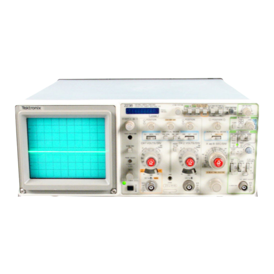
Tektronix 2236 Instruction Manual (351 pages)
Brand:
Tektronix
| Category:
Test Equipment
| Size: 37.19 MB
Table of Contents
Instrument Serial Numbers
2
Table of Contents
3
List of Illustrations
6
List of Tables
7
Operators Safety Summary
8
Servicing Safety Summary
9
Specification
11
Accessories
11
Performance Conditions
11
Introduction
11
Electrical Characteristics
12
Operating Instructions
29
Preparation for Use
29
Safety
29
Line Voltage
29
Power Cord
29
Line Fuse
29
Controls, Connectors, and Indicators
30
Instrument Cooling
30
Display, Power, and Probe Adjust
30
Vertical
31
Horizontal
32
Trigger
34
VERT MODE Trigger Source
35
Counter,Timer, and Multimeter
36
Rear Panel
37
Right Side Panel
37
Multimeter Right Side Panel Connectors
38
Operating Considerations
39
Graticule
39
Grounding
39
Signal Connections
39
Input Coupling Capacitor Precharging
39
Power-Up Checks
40
Ctm Measurement Considerations
40
Status and Error Messages
40
Operator’s Adjustments
42
Baseline Trace
42
Trace Rotation
42
Introduction
42
Probe Compensation
43
Channel 1 AC RMSV
43
Equipment Required for 10X Probe Compensation
44
Theory of Operation
45
Section Organization
45
Integrated Circuit Descriptions
45
Digital Logic Conventions
45
Introduction
45
General Description
46
Oscilloscope
46
Ctm
47
Detailed Circuit Description
48
Vertical Attenuators
48
Input Coupling
48
Oscilloscope
48
Buffer Amplifier and Gain Switching Network
49
Paraphase Amplifier
49
Vertical Preamplifiers
49
Channel Switch and Vertical Output
50
Delay Line Driver
51
Vertical Output Amplifier
51
A/B Sweep Separation Circuit
52
Internal Trigger
52
Trigger Amplifiers and Switching
52
A External Trigger Amplifier
53
A Trigger Generator
53
A Trigger Level Circuit
53
A Schmitt Trigger and TV Trigger Circuit
54
A Sweep Generator and Logic
54
A Trigger Level Comparator
54
A Miller Sweep Generator
55
A Sweep Logic
55
Alternate B Sweep
56
B Miller Sweep Generator
56
B Delay Time Position Comparator
57
B Sweep Logic
57
B Trigger Level Comparator
57
Runs after Delay
57
Alternate Display Switching Logic
58
Horizontal Preamplifier
58
B Z-Axis Logic
58
X-Y Amplifier
59
Horizontal Output Amplifier
59
Z-A Xis Amplifier
60
DC Restorer
61
Power Supply and Probe Adjust
62
Power Input
62
Preregulator
62
Inverter
63
Crt Supply
63
Focus Circuit
63
Low-Voltage Supplies and Fan
63
Cpu System
64
Probe Adjust
64
Microprocessor Reset
64
CPU Clock and Interrupt Timing
64
Ctm
64
Address Decoding Logic
64
Rom
64
Display System
65
Display and Filament Driver
65
Sample Counter Read Ports
65
Time Counter Read Ports
66
Counter Control Latch
66
DMM Control Latch
66
Audio Transducer
66
Pushbutton Read Port
66
Oscilloscope Read Port and Probe Decoder
66
Input/Output Ports
65
Buffered Data Bus Latch
65
Counter Data Bus Switch
65
Display Multiplexing
65
Counter System
66
Input Multiplexer
66
Synchronizer
67
Typical Waveforms for the Nongated Period Function
68
Typical Waveforms for the Gated Period Function
69
Simplified Diagram of the Width Measurement Circuitry
69
Typical Waveforms for the Width Function
70
Phase-Locked Loop
71
Sample and Time Counter Chains
71
Oscillators
71
Scope Sweep System Interface
72
Delay/Delta Time Controller-Digital Section
72
Delay/Delta Time Controller-Analog Section
73
Intensified Zone Controller
73
DMM
73
Typical Waveforms for the Delta Time Func Tion with Valt HI
75
Input Switching Network
76
Input Buffer
77
Input Filter
77
Ac Compensation
78
Multiplexer and Voltage Reference
78
V/F Converter
78
Ohms Reference
79
Overload Protection
80
Relay Drive
80
Serial Interface
80
DMM Power Supply
81
Performance Check Procedure
82
Structure
82
Test Equipment
82
Limits and Tolerances
82
Introduction
82
Purpose
82
Preparation for Checks
83
Test Equipment Required
83
Index to Performance Check Steps
85
Initial Control Settings
86
Procedure Steps
86
Settings for Bandwidth Checks
88
Vertical
86
Horizontal
90
Settings for Timing Accuracy Checks
91
Check Variable Range and Sweep Separation
91
Check Delay Jitter
91
Check Position Range
91
Check Sweep Length
92
Check X Bandwidth
92
Check X Gain
92
Trigger
93
Check External Trigger Ranges
95
Check Single Sweep Operation
95
Ctm
96
Check Delay Time Range and Accuracy
97
Check Delta Time
97
Check Width
97
Check Ac Volts Accuracy
98
Check Ac Volts Zero
98
Check DC Volts Accuracy
98
Check DC Volts Zero
98
Ac CH 1 Readout Checks
99
Check Channel 1 Ac Volts
99
DC CH 1 Readout Checks
99
DC Probe Readout Checks
99
Check Diode Forward Drop
100
Check Ohms
100
Resistance Readout Checks
100
Check Common Mode Rejection
101
Check Normal Mode Rejection
101
Check Temperature
101
Test Setup for DM M Common Mode Check
102
Adjustment Interaction
103
Preparation for Adjustment
103
Adjustment Procedure Section
103
Introduction
103
Purpose
103
Structure
103
Test Equipment
103
Limits and Tolerances
103
Adjustment Interactions
104
Index to Adjustment Procedure Steps
105
Power Supply Limits
106
Power Supply and Crt Display
106
Adjust Trace Alignment
107
Adjust Astigmatism (R874)
107
Adjust CRT Grid Bias (R851)
107
Check High-Voltage Supply
107
Adjust Attenuator Step Balance (RIO and R60)
108
Adjust 2/5 MV DC Balance (R83 and R33)
108
Vertical
108
Adjust Channel 1 Variable Balance (R25)
109
Adjust Channel 2 Invert Balance (R75)
109
Adjust MF/LF Compensation and Gain Balance
109
Adjust Attenuator Compensation
110
Deflection Accuracy Limits
111
Check Input Coupling
112
Check Alternation Operation
112
Check Chop Operation
112
Check Trigger View Gain
113
Adjust 2-MV Peaking Compensation
113
Check Bandwidth Limit Operation
114
Settings for Bandwidth Checks
114
Check Channel Isolation
115
Check Common-Mode Rejection Ratio
115
Check External Z-Axis Operation
115
Check Probe Adjust Operation
116
Check Input Gate Current
116
Horizontal
117
Adjust Magnifier Registration (R749)
118
Check Variable Range
118
Adjust 5-Ns Timing and Linearity (C775 and
119
Check Timing Accuracy and Linearity
119
Settings for Timing Accuracy Checks
119
Adjust X Gain (R760)
120
Check Sweep Separation
120
Check A-Sweep Holdoff
121
Trigger
122
Check Internal Triggering
123
Adjust Trigger Sensitivity (R479 and R627)
123
Adjust P-P Auto Trigger Centering (R434 and
123
Adjust Slope Balance (R471)
123
Check External Triggering
124
Switch Combinations for a Triggering Checks
124
Ctm
126
DC Voltage Readout Checks
129
DC Probe Readout Checks
130
Ac Probe Readout Checks
131
Adjust Beeper Volume (R1832)
131
Check Tem Perature
132
Maintenance
133
Static-Sensitive Components
133
Preventive Maintenance
134
General Care
134
Inspection and Cleaning
134
Interior
134
Introduction
134
External Inspection Checklist
135
Internal Inspection Checklist
135
Cleaning Oscilloscope Circuit Boards
136
Switch Contacts
136
Cleaning CTM Circuit Boards
136
Lubrication
137
Periodic Readjustment
137
Semiconductor Checks
137
Introduction
137
Troubleshooting Aids
137
Circuit Board Locations
138
Circuit Board Interconnection Diagram
138
Power Distribution Diagram
138
Grid Coordinate System
138
Troubleshooting Equipment
139
Troubleshooting Techniques
139
Sem Iconductor Lead Configurations
139
Multipin Connectors
139
Isolate Trouble to a Circuit
140
Check Power Supplies
140
Check Circuit Board Interconnections
140
Check Voltages and Waveforms
140
Transistors
141
Integrated Circuits
141
Diodes
141
Check Individual Components
141
Ctm Troubleshooting Procedure
142
Repair and Adjust the Circuit
142
Kernel and Display System
142
Power-Up Checks and Diagnostic Routines
143
Counter Error Messages
146
DMM
147
Extended Counter
147
DMM Test Error Codes
148
Extended Counter Error Messages
149
Display Verification
150
Period Measurement Loop Test Waveforms.
151
Width Measurement Loop Test Waveforms
152
DMM Serial Interface Loops Test Waveforms
153
Corrective Maintenance
154
Maintenance Precautions
154
Obtaining Replacement Parts
154
Maintenance Aids
154
Interconnections
154
Transistors and Integrated Circuits
156
Soldering Techniques
156
Removal and Replacement Instructions
157
Cabinet
157
CTM Circuit Board
157
Display Circuit Board
159
Cathode-Ray Tube
160
Power-Supply Shield
161
Filter Circuit Board
161
Alt Sweep Circuit Board
161
Circuit Board
162
Tinning Circuit Board
163
Bottom Shield, Attenuator and Timing Circuit-Board Module
164
Front-Panel Circuit Board
164
Main Circuit Board
166
Repackaging for Shipment
167
Selectable Components
168
Trigger Bandwidth Alternation
168
Options
169
Abbreviations
170
List of Assemblies
170
Replaceable Electrical Parts
170
Diagrams
239
Power Supply Isolation Procedure
245
Control Settings
277
DC Voltages
277
AC Woveforms
277
Service
284
A6 Filter Board
284
Test Waveform for Option
312
Parts Ordering Info
320
Item Name
320
Section 10 Replaceable Mechanical Parts
320
Change Information
342
Advertisement
Tektronix 2236 Instruction Manual (60 pages)
Brand:
Tektronix
| Category:
Test Equipment
| Size: 11.53 MB
Table of Contents
Table of Contents
3
Operators Safety Summary
5
General Information
7
Introduction
7
Specification
7
Physical Characteristics
7
Electrical Characteristics
8
Probe Compensation
20
Environmental Characteristics
21
Calibration
24
Repackaging for Shipment
24
Power Cord
25
Line Fuse
25
Пfirst-Time Start up
25
Line Voltage
25
Safety
25
Instrument Cooling
26
Controls , Connectors , and
26
Indicators
26
Display , Power , and Probe Adjust
26
Vertical
27
Horizontal
29
Trigger
30
VERT MODE Trigger Source
31
Counter , Timer , and
32
Multimeter
33
Right Side Panel
33
Rear Panel
33
Multimeter Right Side Panel Connectors
34
General Operating Information
35
Grounding
35
Signal Connections
35
Input Coupling Capacitor
35
Precharging
35
Status and Errors Messages
36
Power- up Checks
36
Ctm Measurement Considerations
36
Power - up Checks
36
Operator's Adjustments
38
Introduction
38
Baseline Trace
38
Trace Rotation
38
Probe Compensation
39
Equipment Required for 10X Probe Compensation
39
Basic Applications/Introduction
41
AC Peak - to - Peak Voltage
41
Basic Applications
41
Common -Mode Rejection
41
Introduction
41
Procedures
41
Voltage Measurements
41
Algebraic Addition
43
Instantaneous DC Voltage
43
Instantaneous Voltage Measurement
43
Amplitude Comparison
44
Television Displays
44
TV Line Signal
44
Voltage Ratios
44
Delayed - Sweep
45
Magnification
45
ПTV Field Signal
45
Magnified Sweep Runs after Delay
46
Pulse Jitter
46
Pulse Jitter Time Measurement
46
Frequency
47
Period
47
Time and Frequency Measurements
47
Triggered Magnified Sweep
47
Width
47
Rise Time
48
Time Interval on Signal Waveform
48
Rise Time
49
Time Difference between Pulses on Two Time Related Signals (Short Method )
49
Time Difference between Points on Two
50
Time Difference between Points on Two Time Related Signals ( General Method)
50
Gated Measurements
51
Phase Difference
51
Multimeter Connections to Forward Bias
52
Multimeter Measurements
52
Resistance and Semiconductor Junctions
52
Ac Rms
53
Continuity
53
Reference Resistance Values
53
Reverse Voltage Drop to Reverse Leakage
53
Channel 1 Volts
54
DC Volts
54
Note
54
Preset Instrument Controls and Obtain a Baseline Trace
54
Temperature
54
Introduction
55
Option 14
55
Optional Accessories
55
Options and Accessories
55
Standard Accessories
55
Change Information
57
Advertisement
Related Products
Tektronix 2230
Tektronix 2235
Tektronix 2232
Tektronix 2235A
Tektronix 2246 MOD A
Tektronix 222
Tektronix 2246
Tektronix 2252
Tektronix 2247A
Tektronix 2215
Tektronix Categories
Test Equipment
Measuring Instruments
Amplifier
Printer
Portable Generator
More Tektronix Manuals
Login
Sign In
OR
Sign in with Facebook
Sign in with Google
Upload manual
Upload from disk
Upload from URL