Tektronix 2235 Additional Operating Information
Tektronix 2235 oscilliscope - controls, connectors, and indicators summary
Hide thumbs
Also See for 2235:
- Instruction manual (229 pages) ,
- Service instructions manual (229 pages) ,
- Operator's manual (53 pages)
Advertisement
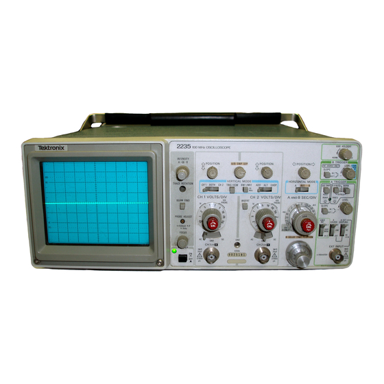
TEKTRONIX 2235 OSCILLISCOPE
CONTROLS, CONNECTORS, AND INDICATORS
The following descriptions are abstracted from the Tektronix operator's manual,
which is intended to familiarize the operator with the location, operation, and
function of the instrument's controls, connectors, and indicators on the Tektronix
2235 Oscilloscope.
POWER, DISPLAY, AND PROBE ADJUST CONTROLS
(1) Internal Graticuules - Eliminate parallax viewing error between the trace and graticule lines, rise-time
amplitude and measurement points are indicated at the left edge of the graticule.
(2) POWER Switch-Turns instrument power on and off.
(3) Power Indicator-An LED that illuminates when
power is available to the instrument and the POWER
switch is set to ON (button in).
(4) FOCUS Control-Adjusts for optimum display definition.
http://web.njit.edu/~ransom/Tektronix2235.html
9/9/2007 12:44 PM
Advertisement
Table of Contents

Related Manuals for Tektronix 2235


Summary of Contents for Tektronix 2235
- Page 1 The following descriptions are abstracted from the Tektronix operator’s manual, which is intended to familiarize the operator with the location, operation, and function of the instrument's controls, connectors, and indicators on the Tektronix 2235 Oscilloscope. POWER, DISPLAY, AND PROBE ADJUST CONTROLS (1) Internal Graticuules - Eliminate parallax viewing error between the trace and graticule lines, rise-time amplitude and measurement points are indicated at the left edge of the graticule.
- Page 2 (5) PROBE ADJUST Connector-Provides an approximately 0.5-V, negative-going, square-wave voltage (at approximately 1 kHz) that permits an operator to compensate voltage probes and to check operation of the oscilloscope vertical system. It is not intended for verifying the accuracy of the vertical gain or time- base circuitry.
- Page 3 (11) CH 1 OR X and CH 2 OR Y Connectors-Provide for application of external signals to the inputs of the vertical deflection system or for an X-Y display. In the X-Y mode, the signal connected to the CH 1 OR X connector provides horizontal deflection, and the signal connected to the CH 2 OR Y connector provides vertical deflection.
-
Page 4: Horizontal Controls
horizontally(X-axis). (16) GND Connector-Provides direct connection to the instrument chassis ground. (17) SERIAL and Mod Slots-The SERIAL slot is imprinted with the instrument's serial number. The Mod slot contains any option number that is installed in the instrument. HORIZONTAL CONTROLS (18) A and B SEC/DIV Switches-Used to select the sweep speeds for the A and B Sweep generators in a 1-2-5 sequence. -
Page 5: Trigger Controls
operation for the horizontal deflection system. A-Horizontal deflection is provided by the A Sweep generator at a sweep speed determined by the A SEC/DIV switch setting. ALT-Alternates the horizontal displays between the A Sweep (with an intensified zone) and the B Delayed Sweep. The A Sweep speed is determined by the setting of the A SEC/DIV switch. - Page 6 for a single-sweep display. This mode operates the same as NORM, except only one sweep is dis- played for each trigger signal. Another sweep cannot be displayed until the SGL SWP RESET push button is momentarily pressed in again to reset the A Sweep circuit. This mode is useful for displaying and photographing either nonrepetitive signals or signals that cause unstable conventional displays (e.g., signals that vary in amplitude, shape, or time).
- Page 7 the A Trigger circuit from the EXT INPUT connector. AC-Signals above 60 Hz are capacitively coupled to the input of the A Trigger circuit. Any dc components are blocked, and signals below 60 Hz are attenuated. DC-All components of the signal are coupled to the input of the A Trigger circuitry. This position is useful for displaying low-frequency or low-repetition-rate signals.
Need help?
Do you have a question about the 2235 and is the answer not in the manual?
Questions and answers