Table of Contents
Advertisement
Quick Links
Advertisement
Table of Contents

Subscribe to Our Youtube Channel
Related Manuals for TYAN GA80-B7081


Summary of Contents for TYAN GA80-B7081
- Page 1 GA80-B7081 Service Engineer’s Manual http://www.tyan.com...
- Page 2 Corporation and has been reviewed for accuracy and reliability prior to printing. MiTAC assumes no liability whatsoever, and disclaims any ® express or implied warranty, relating to sale and/or use of TYAN products including liability or warranties relating to fitness for a particular purpose or merchantability.
- Page 3 There will be danger of explosion if battery is incorrectly replaced. Replace only with the same or equivalent type recommended by manufacturer. Dispose of used battery according to manufacturer instructions and in accordance with your local regulations. http://www.tyan.com...
-
Page 4: About This Manual
/personnel with hardware knowledge of personal computers. This manual consists of the following parts: Chapter 1: Overview Provides an introduction to the TYAN GA80-B7081 barebones, standard parts list, describes the external components, gives a table of key components, and provides block diagram of the system. -
Page 5: Safety And Compliance Information
Safety and Compliance Information Before installing and using TYAN GA80-B7081, take note of the following precautions: ·Read all instructions carefully. ·Do not place the unit on an unstable surface, cart, or stand. ·Do not block the slots and opening on the unit, which are provided for ventilation. -
Page 6: Safety Information
To reduce the risk of bodily injury, electric shock, fire and damage to the equipment, observe all precautions included in this guide. You must become familiar with the safety information in this guide before you install, operate, or service TYAN products. Symbols on Equipment Warning. This symbol indicates the presence of hazardous energy circuits or electric shock hazards. -
Page 7: General Precautions
· Do not attempt to move a fully loaded rack. Remove equipment from the rack before moving it. · Do not attempt to move a rack on an incline that is greater than 10 degrees from the horizontal. · Make sure the rack is properly secured to the floor or ceiling. http://www.tyan.com... - Page 8 This will reduce the risk of personal injury, fire, or damage to the equipment. The total rack load should not exceed 80 percent of the branch circuit rating. Consult the electrical authority having jurisdiction over your facility wiring and installation requirements. http://www.tyan.com...
- Page 9 · Dispose of used batteries according to the instructions of the manufacturer. Do not dispose of batteries with the general household waste. To forward them to recycling or proper disposal, use the public collection system or return them to TYAN, your authorized TYAN partner, or their agents. http://www.tyan.com...
- Page 10 Equipment Modifications · Do not make mechanical modifications to the system. TYAN is not responsible for the regulatory compliance of TYAN equipment that has been modified. Equipment Repairs and Servicing · The installation of internal options and routine maintenance and service...
-
Page 11: Table Of Contents
Table of Contents Chapter 1: Overview ................ 13 About the TYAN GA80-B7081 ..........13 Product SKU ................13 Features .................. 14 Standard Parts List ..............23 1.4.1 Box Contents ..............23 1.4.2 Accessories ..............24 About the Product ..............25 1.5.1... - Page 12 Chapter 7: Diagnostics ..............142 Flash Utility ................142 AMIBIOS Post Code (Aptio) ..........143 Appendix I: Fan and Temp Sensors ..........152 Appendix II: Cable Connection Tables ........157 Appendix III: FRU Parts Table ............158 Appendix IV: Technical Support ..........159 http://www.tyan.com...
-
Page 13: Chapter 1: Overview
The GA80-B7081 not only empowers your company in nowadays IT demand but also offers a smooth path for future application usage. ® TYAN is also proud to deliver the GA80-B7081 in a version that can support up ® to four 2.5‖ hot-swap hard drives. The GA80-B7081 uses TYAN ‘s latest chassis featuring a robust structure and a solid mechanical enclosure. -
Page 14: Features
Features TYAN GA80-B7081 (B7081G80V4HR-2T-N) Form Factor 1U Rackmount Chassis Model GA80 System Dimension (D x W x 31.50" x 17.32" x 1.73" (800 x 440 x 43.9mm) Motherboard S7081GM3NR-2T-N Buttons (1) PWR / (1) RST / (1) ID Front Panel... - Page 15 Please refer to our Intel OS supported list. System FCC (DoC) Class A Regulation CE (DoC) Operating Temp. 10° C ~ 35° C (50° F~ 95° F) Operating Non-operating Environment - 40° C ~ 70° C (-40° F ~ 158° F) Temp. http://www.tyan.com...
- Page 16 In/Non-operating 90%, non-condensing at 35° C Humidity RoHS 6/6 RoHS Compliant Barebone (1) GA80-B7081 w/NV Tesla-aware FW Barebone Package (1) Web User's manual / (1) Quick Installation Manual Contains Guide Installation CD (1) TYAN installation CD TYAN GA80-B7081 (B7081G80V4HR-2T-X) Form Factor...
- Page 17 (1) PCI-E Gen3 x8 slot / (3) PCI-E Gen3 x16 slots M7081-R8-1L, PCI-E Gen3 x8 1U riser card Expansion (right) / M7081-R16-1F, PCI-E Gen3 x16 1U riser Pre-install TYAN Slots card (right) / M7081-L16-1F-1, PCI-E Gen3 x16 Riser Card 1U riser card (left) / M7081-L16-1F-2, PCI-E Gen3...
- Page 18 - 40° C ~ 70° C (-40° F ~ 158° F) Temp. Environment In/Non-operating 90%, non-condensing at 35° C Humidity RoHS 6/6 RoHS Compliant (1) GA80-B7081 w/Intel Xeon Phi-aware FW Barebone Barebone Package (1) Web User's manual / (1) Quick Installation Contains Manual Guide Installation CD...
- Page 19 (1) PCI-E Gen3 x8 slot / (3) PCI-E Gen3 x16 slots M7081-R8-1L, PCI-E Gen3 x8 1U riser card (right) / M7081-R16-1F, PCI-E Gen3 x16 1U riser Expansion Slots Pre-install TYAN card (right) / M7081-L16-1F-1, PCI-E Gen3 x16 Riser Card 1U riser card (left) / M7081-L16-1F-2, PCI-E...
- Page 20 - 40° C ~ 70° C (-40° F ~ 158° F) Temp. Environment In/Non-operating 90%, non-condensing at 35° C Humidity RoHS RoHS 6/6 Compliant Yes (1) GA80-B7081 w/NV Tesla-aware FW Barebone Barebone Package (1) Web User's manual / (1) Quick Installation Contains Manual Guide...
- Page 21 (1) PCI-E Gen3 x8 slot / (3) PCI-E Gen3 x16 slots M7081-R8-1L, PCI-E Gen3 x8 1U riser card (right) / M7081-R16-1F, PCI-E Gen3 x16 1U riser Expansion Slots Pre-install TYAN card (right) / M7081-L16-1F-1, PCI-E Gen3 x16 Riser Card 1U riser card (left) / M7081-L16-1F-2, PCI-E...
- Page 22 - 40° C ~ 70° C (-40° F ~ 158° F) Temp. Environment In/Non-operating 90%, non-condensing at 35° C Humidity RoHS RoHS 6/6 Compliant Yes (1) GA80-B7081 w/Intel Xeon Phi-aware FW Barebone Barebone Package (1) Web User's manual / (1) Quick Installation Contains Manual Guide...
-
Page 23: Standard Parts List
Standard Parts List This section describes the GA80-B7081 package contents and accessories. Open the box carefully and ensure that all components are present and undamaged. The product should arrive packaged as illustrated below. 1.4.1 Box Contents Component Description 1U chassis, (4) hot swap HDD bays ®... -
Page 24: Accessories
If any items are missing or appear damaged, contact your retailer or browse to ® TYAN ‘s website for service: http://www.tyan.com ® The web site also provides information of other TYAN products, as well as FAQs, compatibility lists, BIOS settings, etc. ® TYAN Motherboard Drive CD... -
Page 25: About The Product
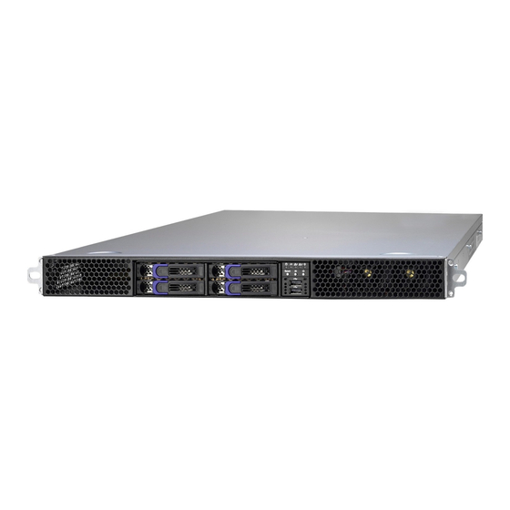
About the Product The following views show you the product. 1.5.1 System Front View http://www.tyan.com... -
Page 26: Led Control And Hdd Led Definitions
Access / Green Blinking Link Green Linking / Green Solid On Off Link / Green Off Off Link LAN2 Access Green Access / Green Blinking Link Green Linking / Green Solid On Off Link / Green Off Off Link http://www.tyan.com... - Page 27 Status LED Description Color: Green Color: Orange Solid On Drive present, no activity Blinking Drive present, with activity Do not care Solid On HDD Fail Do not care Blinking @1Hz Drive Locate Identify Do not care Blinking @4Hz Rebuilding http://www.tyan.com...
-
Page 28: System Rear View
1.5.3 System Rear View Description Delta 1600W (1+1) redundancy Power Supply LAN3 (shared with IPMI)+2 USB3.0 ports Serial Port LAN2 and LAN1 (from left to right) ID LED Button & ID LED VGA Port Expansion Slots http://www.tyan.com... -
Page 29: Lan And Id Led Definitions
LAN can achieve GbE or when with Intel X540-AT2 LAN can achieve 10GbE or when with Intel I210 chipset LAN can achieve Gbe ID LED Status LED Color Behavior Remark Normal ID LED Blue Local and Located Solid on remote http://www.tyan.com... -
Page 30: System Top View
1.5.5 System top view Description Description HDD cage GPU card assembly #3 HDD Backplane Board Expansion card assembly System Fans Power Supply GPU card assembly #1 Air Duct NOTE:Fan3 share with Fan12, GPU card assembly #2 Fan4/Fan13,Fan5/F14, Fan2/Fan11, Fan1/Fan10,Fan8/Fan17,Fan9/Fan18 http://www.tyan.com... -
Page 31: Chapter 2: Setting Up
Caution! To avoid damaging the motherboard and associated components, do not use torque force greater than 7kgf/cm (6.09 lb/in) on each mounting screw for motherboard installation. Do not apply power to the board if it has been damaged. http://www.tyan.com... -
Page 32: Precautions
Working on a system that is connected to a power supply can be extremely dangerous. Follow the guidelines below to avoid damage to GA80-B7081 or injury to yourself. Ground yourself properly before removing the top cover of the system. -
Page 33: Installing Motherboard Components
CPUs, memory modules, HDD and Add-On cards. 2.1.1 Removing the Chassis Cover Follow these instructions to remove the GA80-B7081 chassis cover. Remove the top screw on the chassis cover and slide the chassis cover in the direction of arrow. -
Page 34: Installing The Cpu And Heatsink
Follow the steps below to install the processor and heatsink. Install the CPU Locate the CPU socket and start installing CPU from CPU0. Pull the CPU lever up to unlock the CPU socket. Open the socket to a fully open position. http://www.tyan.com... - Page 35 Take off the CPU Socket protection cap. Place the CPU in the CPU socket. Make sure the gold arrow is located in the right direction. Close the socket and press the CPU socket lever down to secure the CPU. http://www.tyan.com...
- Page 36 Place the air duct on top of the heatsink and make sure it is align with the gutter as illustrate in the image. The heatsink and air duct installation is over. http://www.tyan.com...
-
Page 37: Installing The Memory
1. Press the memory slot locking levers in the direction of the arrows as shown in the following illustration. Always started from CPU0 A0. 2. Align the memory module with the slot. When inserted properly, the memory slot locking levers lock automatically onto the indentations at the ends of the module. http://www.tyan.com... - Page 38 3. Populate the same DIMM type in each channel, specifically - Use the same DIMM size - Use the same # of ranks per DIMM 4. Dual-rank DIMMs are recommended over single-rank DIMMs. http://www.tyan.com...
- Page 39 3. Populate the same DIMM type in each channel, specifically - Use the same DIMM size - Use the same # of ranks per DIMM 4. Dual-rank DIMMs are recommended over single-rank DIMMs. http://www.tyan.com...
- Page 40 http://www.tyan.com...
-
Page 41: Installing Hard Drives
2.1.4 Installing Hard Drives The GA80-B7081 barebone supports (4) 2.5‖ hard drives. Follow these instructions to install a hard drive. Warning!!! Always install the hard disk drive to the chassis after the chassis is secured on the rack. Press the locking lever latch in the direction of arrow. - Page 42 Place a hard drive into the drive tray. Use four screws to secure the HDD. Reinsert the HDD tray into the chassis. Press the locking lever to secure the hard drive. Repeat the same procedures to install other HDD trays. http://www.tyan.com...
-
Page 43: Installing The Add-On Card
2.1.5 Installing the Add-On Card The GA80-B7081 has one preinstalled M7081-R8-1L riser card. You can install an Add-On card into the expansion slot which is available with riser card. The following instructions are for Add-On card installation. You may refer to the procedures below for the installation. - Page 44 4. Reinstall the PCIE bracket into the chassis and secure with 2 screws. http://www.tyan.com...
-
Page 45: Rack Mounting
Mounting Ears screw Pack x 1 2.2.1 Installing the Server in a Rack Follow these instructions to mount the TYAN GA80-B7081 into an industry standard 19‖ rack. NOTE: Before mounting the TYAN GA80-B7081 in a rack, ensure that all internal components have been installed and that the unit has been fully tested. -
Page 46: Installing The Outer Rails To The Rack
Install the rail to the rack. Repeat the same procedures for the other rail. Secure the outer rail to the rack using 4 (A) M5 screws and washers (2 sets front / 2 sets rear) for each side. Secure the rails to the rack as shown. http://www.tyan.com... -
Page 47: Installing The Inner Rails To The Chassis
2.2.3 Installing the inner Rails to the Chassis 1. Press the button to pull out the inner rail from the outer rail of the GA80-B7081 sliding rails. 2. Align the inner sliding rail (1) on the side of the server, and pull towards the arrow (2) to secure the six hooks. -
Page 48: Rack Mounting The Server
2.2.4 Rack mounting the Server To install the chassis to the rack Then press the button to push the whole system into the rack. Push the chassis back into the rack. http://www.tyan.com... - Page 49 To removing the chassis from a rack Follow these instructions to remove the TYAN GA80-B7081 from an industry standard 19‖ rack. Hold the mounting ears to pull out the chassis from the rack. Press the button to unlock the chassis from the rails.
-
Page 50: Chapter 3: Replacing Pre-Installed Components
This chapter explains how to replace the pre-installed components, including the Motherboard, M1706G62 Front panel board, M7081G81A-BP6-4 SATA HDD backplane, M7081-R16-1F, M7081-L16_1F-1 M7081-L16-1F-2 PCI-E Riser card, System fans, and Power supply unit etc. 3.0.2 Disassembly Flowchart The following flowchart outlines the disassembly procedure. http://www.tyan.com... -
Page 51: Removing The Cover
Before replacing any parts you must remove the chassis cover. Follow Section 2.1.1 Removing the Chassis Cover (page 33) to remove the cover of the GA80-B7081. Replacing the Front Panel Board Follow these instructions to replace the M1706G62-FPB Front Panel Board. - Page 52 4 Unscrew to take out the front panel board. 5 Replace a new front panel board and screw it to the front panel tray. http://www.tyan.com...
-
Page 53: M1706G62 Front Panel Board Features
1.5.1 System Front View (Per Node) for details on Front Panel LEDs and buttons. 3.2.2 Front Panel Board Connector Pin Definition FPIO Connector Signal Signal PW_ LED+ VCC- IDLED+ PW_LED- IDLED- HD_LED+ FAULT_LED1- HD_LED- FAULT_LED2- PWR_SW# LAN1_LED+ LAN_LED- RESET# ID_SW# TEMP_SENSOR LAN2_LED+ HD_FAIL_LED- LAN_LED- http://www.tyan.com... - Page 54 1 VCC_USB0 Power connect to 5V (for USB) 6 USB_P1_P USB_P1 + 2 VCC_USB1 Power connect to 5V (for USB) 7 GND Ground 3 USB_P0_N USB_P0 - 8 GND Ground 4 USB_P1_N USB_P1 - 9 NC 5 USB_P0_P USB_P0 + 10 NC http://www.tyan.com...
-
Page 55: Replacing The System Fan
Replacing the System Fan There are totally nine system fans in the GA80-B7081.Four at front, three in the middle, and two at back. Follow these instructions to replace the cooling fans in the system. 1. Locate the cooling fans in your system. - Page 56 3. Lift the fan up from the chassis. 4. After replacing the new fans, reinstall the fans into the chassis. 5. Connect the fan cables to the motherboard fan connectors. http://www.tyan.com...
-
Page 57: Replacing The Hdd Backplane
Replacing the HDD Backplane 1. Disconnect all the cables connected to the HDD Backplane. 2. Remove the two screws securing the bracket to the chassis base. http://www.tyan.com... -
Page 58: M7081G81A-Bp6-4 Hdd Backplane Features
3.4.1 M7081G81A-BP6-4 HDD Backplane Features Front View Rear View (4) port 2.5‖ SAS/SATA 6Gb/s & hot-swap support Integrated I/O (1) Mini-SAS HD connector (1) 2x4 Pin Power connector http://www.tyan.com... -
Page 59: M7081G81A-Bp6-4 Hdd Connector Pin Definitions
3.4.2 M7081G81A-BP6-4 HDD Connector Pin Definitions PW3: Power Connector Signal Signal P12V P12V P12V P12V J11: Header (5 X2 Pin) for CPLD Signal Signal TCK_A TDO_A VDD_3P3_RUN TMS_A TDI_A http://www.tyan.com... -
Page 60: Replacing Pci-E Riser Cards
Follow the instructions below to disassemble the M7081-R16-1F, M7081-L16_1F-1 M7081-L16-1F-2 M7081-R8-1L PCI-E riser cards. Uninstalling the M7081-L16-1F riser card 1 There are three PCI bracket in the GA80-B7081 chassis. 2 Remove the 4 screws secure the PCI bracket and lift the bracket up. http://www.tyan.com... - Page 61 1 Follow the same procedure to detach the other PCI bracket. Unscrew the M7081-R16-1F, M7081-L16_1F-1 riser card to replace a new one if necessary. 3 Follow the steps described earlier in reverse to reinstall the M7081-R16-1F, M7081-L16_1F-1 riser card. http://www.tyan.com...
- Page 62 Uninstalling the M7081-R8-1L riser card Follow the procedure in chapter 2.1.6 Installing the PCIE riser card to detach the riser card bracket. 1 Unscrew the M7081-R8-1L riser card to replace a new one if necessary. http://www.tyan.com...
-
Page 63: Pcie Riser Card Features
3.5.1 PCIE Riser card Features M7081-R16-1F riser card M7081-L16-1F-1 riser card M7081-L16-1F-2 riser card M7081-R8-1L riser card http://www.tyan.com... -
Page 64: Replacing The Power Supply
1 Located at the power supply usage. 2 Press and hold the latch to pull the power supply out. 3 After replacing a new power supply, press and hold the latch to push the power supply back into the chassis. http://www.tyan.com... - Page 65 http://www.tyan.com...
-
Page 66: Removing Motherboard Procedures
Before replacing the motherboard or certain components, disconnect cables connected to the motherboard then the motherboard can be easily take out. Follow these instructions to remove all motherboard cables. Disconnect the 8-pin power cables, mini SAS cable and Front Panel cable. Disconnect the system fan cable. http://www.tyan.com... -
Page 67: Removing The Motherboard
After removing all of the aforementioned cables, follow the instructions below to remove the motherboard from the chassis. Remove the heatsink and processor if installed. Remove the eleven screws securing the motherboard to the chassis. Remove the mylar from the chassis. Carefully lift the motherboard from the chassis. http://www.tyan.com... -
Page 68: Chapter 4: Installing Gpu Cards
1. Take out the PCI bracket. Turn the bracket over and unscrew to remove the GPU card bracket as shown. 2. Remove the 2 screws secure the PCI Riser expansion slot. 3. Remove the I/O dummy brackets. Insert the GPU card to the PCI bracket and secure it with two screws. http://www.tyan.com... - Page 69 5. Install the Intel® GPU bracket to the Intel® Phi GPU card and secure with 4 M3 screws. 6. Insert the Intel® Phi GPU card onto the M7081-L16-1F-2 riser card and secure with 2 screws on the expansion slot. http://www.tyan.com...
- Page 70 7. Reinstall the GPU bracket and secure with 2 M3 screws on one side. 8. Install the GPU bracket and secure with 2 screws at location 2. 9. Put the PCI bracket back to the chassis. http://www.tyan.com...
-
Page 71: Chapter 5: Motherboard Information
Caution! To avoid damaging the motherboard and associated components, do not use torque force greater than 7kgf/cm (6.09 lb/in) on each mounting screw for motherboard installation. Do not apply power to the board if it has been damaged. http://www.tyan.com... -
Page 72: Board Image
Board Image This picture is representative of the latest board revision available at the time of publishing. The board you receive may not look exactly like the above picture. http://www.tyan.com... -
Page 73: Block Diagram
Block Diagram http://www.tyan.com... -
Page 74: Motherboard Mechanical Drawing
Motherboard Mechanical Drawing http://www.tyan.com... -
Page 75: Board Parts, Jumpers And Connectors
The board you have received may not look exactly like the above diagram. The DIMM slot numbers shown above can be used as a reference when reviewing the DIMM population guidelines shown later in the manual. For the latest board revision, please visit our web site at http://www.tyan.com. http://www.tyan.com... - Page 76 Jumpers & Connectors Connectors 13. 8-pin FAN Connector 1.TYAN Module Header(DBG_HD1) (SYS_FAN7/16,J192) 2.stacked 2 USB v3.0 and LAN port 14. 8-pin FAN Connector connector#3 shard with IPMI (SYS_FAN6/15,J189) 15. 8-pin FAN Connector 3.VGA & COM Port (SYS_FAN5/14,J187) 16. 8-pin FAN Connector 4.LAN Port Connector#2(J184)
- Page 77 Do not mix 8-pin Fan headers with 4-pin Fan headers. Mixing these fan headers will cause problems to the system. These connectors are only for the barebone. J185:FAN3&12 J186:FAN4&13 J187: FAN5&14 J188:FAN2&11 J189: FAN6&15 J190: FAN8&17 J191:FAN9&18 J192: FAN7&16 J200: FAN1&10 http://www.tyan.com...
- Page 78 HD_LED- SYS_FAULT_LED- PWR_SW# LAN1_ACTLE+ LAN1LED- RST_SW# SYS_ID_SW# INTRUSION# LAN2LED+ NMI_SW# LAN2LED- USB1: USB Front Panel Header (blue) Signal Signal USBD- USBD- USBD+ USBD+ J193: Vertical (Type A) USB3.0 Connectors Signal Signal USB2 P0_RX_N USB2 P0_RX_P USB3P0_TX_N USB3P0_TX_P USB3P0_N USB3P0_P http://www.tyan.com...
- Page 79 P3V3_AUX ID_SW_L State Color Description Blue System identified System not identified NOTE: The ID LED can be activated remotely using IPMI. Please visit the TYAN Web Site at http://www.tyan.com to download the latest IPMI Configuration Guide for more details. http://www.tyan.com...
- Page 80 3PHD_5: BIOS Recovery Pin Header Signal FM_BIOS_RCVR_BOOT_N Pin 1-2 Closed: Normal Mode (Default) Pin 2-3 Closed: Recovery Mode 3PHD_8: Flash Security Override Jumper Signal MFG_MODE_N Pin 1-2 Closed: Normal Mode (Default) Pin 2-3 Closed: Security Override http://www.tyan.com...
-
Page 81: Chapter 6: Bios Setup
Exit current menu <F1> General help <F2> Previous values <F3> Load the Optimal default configuration values of the menu <F4> Save and exit <K> Scroll help area upwards <M> Scroll help area downwards <PgUp> / <PgDn> Move cursor to next/previous page http://www.tyan.com... - Page 82 BIOS menus are continually changing due to continual BIOS updates over the product lifespan of the motherboard. The BIOS menus provided are current as of the date when this manual was written. Please visit TYAN‘s website at http://www.tyan.com for information on BIOS updates available for this specific motherboard.
-
Page 83: Main Menu
It displays BIOS related information. Memory Information This displays the total memory size. System Date Adjust the system date. MM (Months): DD (Days): YYYY (Years) System Time Adjust the system clock. HH (24 hours format): MM (Minutes): SS (Seconds) Access Level Read only. http://www.tyan.com... -
Page 84: Advanced Menu
This section facilitates configuring advanced BIOS options for your system. ACPI Settings System ACPI Parameters. Onboard Device Configuration Onboard Device Configuration Hardware Health Configuration Hardware health Configuration Parameters. Watchdog Timer Configuration Watchdog Configuration SIO Configuration SIO Configuration S5 RTC Wake Settings S5 RTC Wake Configuration http://www.tyan.com... - Page 85 Serial Port Console Redirection Serial Port Console Redirection. PCI Subsystem Settings PCI subsystem settings CSM Configuration CSM Configuration USB Configuration USB Configuration Parameters. http://www.tyan.com...
- Page 86 Enable Hibernation Enables or disables System ability to Hibernate (OS/S4 Sleep State). This option may not be effective with some OS. Disabled / Enabled NOTE: Enable Hibernation Settings submenu appears when Enable ACPI Auto Configuration is set to [Disabled]. http://www.tyan.com...
- Page 87 LAN Configuration is set to [Enabled]. LAN1 OPROM Enable/Disable Load Option ROM for OnBoard Network Controller. Disabled / PXE / iSCSI LAN2 OPROM Enabled/Disabled the LAN Option ROM in the Chipset. Disabled / PXE LAN3 OPROM Enable or Disable NMI function. Disabled / PXE http://www.tyan.com...
- Page 88 GPU Area Fan control GPU area Fan control help Auto / 30% Duty Cycle / 50% Duty Cycle / 70% Duty Cycle / 85% Duty Cycle / 100% Duty Cycle BMC Alert Beep BMC Alert Beep On/Off. On / Off http://www.tyan.com...
- Page 89 6.3.3.1 Sensor Data Register Monitoring When you enter the Sensor Data Register Monitoring submenu, you will see the following dialog window pop out. Please wait 8~10 seconds. NOTE 1: SDR can not be modified. Read only. http://www.tyan.com...
- Page 90 http://www.tyan.com...
- Page 91 http://www.tyan.com...
- Page 92 Disabled / POST / OS / PowerOn NOTE: Watch Dog Timer will not appear when Watch Dog Mode is set to [Disabled]. Watch Dog Timer Watch Dog Timer Help. 2 MINS / 4 MINS / 6 MINS / 8 MINS / 10 MINS http://www.tyan.com...
- Page 93 6.3.5 Super IO Configuration Super IO Chip Read only. http://www.tyan.com...
- Page 94 / IO=3F8h, IRQ=3, 4, 5, 6, 7, 9, 10, 11, 12; / IO=2F8h; IRQ=3, 4, 5, 6, 7, 9, 10, 11, 12; / IO=3E8h, IRQ=3, 4, 5, 6, 7, 9, 10, 11, 12; / IO=2E8h, IRQ=3, 4, 5, 6, 7, 9, 10, 11, 12; http://www.tyan.com...
- Page 95 Select 0~23. For example, enter 3 for 3am and 15 for 3 pm. Wake up minute Select 0~59. Wake up second Select 0~59. NOTE: When Wake system from S5 is set to [Dynamic Time], the following item will appear. Wake up minute increase 1-5. http://www.tyan.com...
- Page 96 Console Redirection Settings The settings specify how the host computer (which the user is using) will exchange data. Both computers should have the same or compatible settings. NOTE: Console Redirection Settings menu only appear when Console Redirection was set to [Enabled]. http://www.tyan.com...
- Page 97 0 if the num of 1‘s in the data bits is even. Odd: parity bit is 0 if the num of 1‘s in the data bits is odd. Mark: parity bit is always 1. Space: parity bit is always 0. Mark and Space parity do not allow for error detection. None / Even / Odd / Mark / Space http://www.tyan.com...
- Page 98 VT100 / LINUX / XTERMR6 / SCO / ESCN / VT400 Redirection After BIOS POST The settings specify if bootloader is selected than Legacy console redirection is disabled before booting to Legacy OS. Default value is always enable means Legacy. Always Enable / Bootloader http://www.tyan.com...
- Page 99 115200 / 9600 / 19200 / 38400 / 57600 Flow Control Flow Control can prevent data loss from buffer overflow. When sending data, if the receiving buffers are full, a ‗stop‘ signal can be sent to stop the data flow. Once the http://www.tyan.com...
- Page 100 ‗start‘ signal can be sent to restart the flow. Hardware flow control uses two wires to send start/stop signal. None / Hardware RTS/CTS Data Bits / Parity / Stop Bits Read only. http://www.tyan.com...
- Page 101 Space (Only if System Supports 64 bit PCI Decoding). Enabled / Disabled SR-IOV Support If system has SR-IOV capable PCIe Devices, this option enables or disables Single Root IO Virtualization Support. Disabled / Enabled PCI Express Settings Configure PCI express device settings. http://www.tyan.com...
- Page 102 PCI Express Settings Maximum Payload Set Maximum Payload of PCI Express Device or allow System BIOS to select the value. Auto / 128 Bytes / 256 Bytes / 512 Bytes / 1024 Bytes / 2048 Bytes / 4096 Bytes http://www.tyan.com...
- Page 103 Legacy / Do not launch / UEFI Storage Controls the execution of UEFI and Legacy Storage OpROM. Legacy / Do not launch / UEFI Video Controls the execution of UEFI and Legacy Video OpROM Legacy / Do not launch / UEFI http://www.tyan.com...
- Page 104 Other PCI Devices Determines OpROM execution policy for devices other than Network, Storage, or Video. Legacy / Do not launch / UEFI http://www.tyan.com...
- Page 105 This is a workaround for OSes without XHCI hand-off support. The XHCI ownership change should be claimed by XHCI driver. Disabled / Enabled EHCI Hand-off This is a workaround for OSes without EHCI hand-off support. The EHCI ownership change should be claimed by EHCI driver. Disabled / Enabled http://www.tyan.com...
- Page 106 Mass storage device emulation type. AUTO‘ emumerates devices according to their media format. Optical drives are emulated as ‗CDROM‘. Drives with no media will be emulated according to a drive type. Auto / Floppy / Forced FDO/ Hard Disk / CD-ROM http://www.tyan.com...
-
Page 107: Intel Rc Setup
Displays and provides option to change teh QPI Settings. Memory Configuration Displays and provides option to change the Memory Settings. IIO configuration Displays and provides option to change the IIO Settings. PCH configuration Displays and provides option to change the PCH Settings. http://www.tyan.com... - Page 108 Miscellaneous Configuration Displays and provides option to change the Miscellaneous Settings. Runtime Error Logging Press <Enter> to view or change the runtime error log configuration. http://www.tyan.com...
-
Page 109: Processor Configuration
When disabled, forces the XD feature flag to always return 0. Enabled / Disabled Enable Intel TXT Support Enable Intel Trusted Execution Technology Configuration. Please disable ―EV DFX Features‖ when TXT is enabled. Disabled / Enabled Enables the vanderpool Technology, takes effect after reboot. Enabled / Disabled http://www.tyan.com... - Page 110 6.4.1.1 Per-Socket Configuration http://www.tyan.com...
- Page 111 6.4.1.1.1 CPU Socket 0 / Socket 1 Configuration Cores Enabled Number of Cores to Enable. 0 means all cores. 14 Cores available. IOT Cfg Cbo Bitmap (Hex) Each bit enables IOT/OCLA for a CBo. http://www.tyan.com...
-
Page 112: Advanced Power Management Configuration
Advanced Power Management Configuration Power Technology Enable the power management features. Energy Efficient / Disabled / Custom NOTE: CPU P State Control and CPU C State Control submenu can be modified in user mode when Power Technology is set to [Custom]. http://www.tyan.com... - Page 113 When eneabled, OS sets CPU frequency according load. When disabled, CPU frequency is set at max non-turbo. Enabled / Disabled Turbo Mode Turbo mode allows a CPU logical processor to execute a higher frequency when enough power is available not exceed CPU defined limits. Enabled / Disabled http://www.tyan.com...
- Page 114 C0/C1 state / C2 state / C6 (non Retention) state / C6 (Retention) state CPU C3 report Enable/Disable CPU C3 (ACPI C2) report to OS. Recommended to be disabled. Disabled / Enabled CPU C6 report Enable/Disable CPU C6 (ACPI C2) report to OS. Recommended to be enabled. Disabled / Enabled http://www.tyan.com...
-
Page 115: Common Refcode Configuration
MMIOH Base [63:32] must be between 4032-4078. 56T / 40T / 24T / 16T / 4T MMIO High Size Select MMIO High Size. 256G / 128G / 512G / 1024G Numa Enable or Disable Non uniform Memory Access (NUMA). Enabled / Disable http://www.tyan.com... -
Page 116: Qpi Configuration
6.4.4 QPI Configuration QPI General Configuration Displays and provides option to change the QPI General Settings. http://www.tyan.com... - Page 117 Allows for selecting the QPI Link Frequency. Auto / 6.4GB/s / 8.0GB/s / 9.6GB/s / Auto Limited Link L0p Enable Link L0p Enable: Disable, Enable (default) Disabled / Enabled Link L1p Enable Link L1p Enable: Disable, Enable (default) Disabled / Enabled http://www.tyan.com...
- Page 118 6.4.4.1.1 QPI Status QPI Status Read only http://www.tyan.com...
-
Page 119: Memory Configuration
Auto / Enforce POR / Disabled / Enforce Stretch Goals NOTE: When Enforce POR is set to [Disabled], Memory Frequency will appear. Memory Frequency Maximum Memory Frequency Selections in Mhz. Do not select Reserved. Auto / 1600 / 1867 / 2133 http://www.tyan.com... - Page 120 6.4.5.1 Memory Topology This submenu can‘t be modified in user mode. Read only. http://www.tyan.com...
- Page 121 6.4.5.2 Memory Thermal Set Throttling Mode Configure Thermal Throttling Mode. Select OLTT or CLTT mode. Disabled / OLTT / CLTT http://www.tyan.com...
- Page 122 Enable/Disable RAS modes. Enabling Sparing and Mirroring is not supported. In case if enabled, Sparing will be selected. Disabled / Mirror / Lockstep Mode Lockstep x4 DIMMs Enable/Disasle Lockstep for x4 DIMMs. Auto / Disabled / Enabled Memory Rank Sparing Enable/Disable Memory Rank Sparing. Disabled / Enabled http://www.tyan.com...
-
Page 123: Iio Configuration
IIO Configuration EV DFX Features Set this option to allow DFX Lock Bits to remain clear. Disabled / Enabled Intel VT for Directed I/O (VT-d) Press <Enter> to bring up the Intel VT for Directed I/O (VT-d) Configuration menu. http://www.tyan.com... - Page 124 6.4.6.1 Intel VT for Directed I/O (VT-d) Intel VT for Directed I/O (VT-d) Enable/Disable Intel Virtualization Technology for Directed I/O (VT-d) by reporting the I/O device assignment to VMM through DMAR ACPI Tables. Enabled / Disabled http://www.tyan.com...
-
Page 125: Pch Configuration
6.4.7 PCH Configuration PCH Devices Enable/Disable Intel® IO Controller Hub devices PCH SATA Configuration SATA devices and settings. USB Configuration USB Configuration Settings. http://www.tyan.com... - Page 126 6.4.7.1 PCH Devices PCH State after G3 Select S0/S5 for ACPI state after a G3. S0 / S5 / Last State http://www.tyan.com...
- Page 127 Configure SATA as Idedntify the SATA port is connected to Solid State Drive or Hard Disk Drive. IDE / AHCI / RAID Support Aggressive Link Power Management Enable/Disable SALP. Enabled / Disabled SATA Port 0/1/2/3/4 Read only. Software Preserve Read only. http://www.tyan.com...
- Page 128 Otherwise all drives spin up at boot. Disabled / Enabled SATA Device Type Identify the SATA port is connected to Solid State Drive or Hard Disk Drive. Hard Disk Drive / Solid State Drive http://www.tyan.com...
- Page 129 When XHCI Mode is sent to [Disabled], the following items will appear. EHCI1 Control the USB EHCI (USB2.0) functions. One EHCI controller must always be enabled. Enabled / Disabled EHCH2 Control the USB EHCI (USB2.0) functions. One EHCI controller must always be enabled. Enabled / Disabled http://www.tyan.com...
-
Page 130: Miscellaneous Configuration
6.4.8 Miscellaneous Configuration Active Video Select active Video type. Offboard Device / Onboard Device http://www.tyan.com... -
Page 131: Runtime Error Logging
6.4.9 Runtime Error Logging System Errors System Error enabling and logging setup option. Enabled / Disabled Memory Error Enabling Press <Enter> to view or change the Memory errors enabling options. http://www.tyan.com... - Page 132 6.4.9.1 Memory Error Enabling Memory corrected Error enabling Enable / Disable Memory corrected Errors. Enabled / Disabled Spare Interrupt Select SMI/CMCI/ErrPin for spare interrupt. SMI / CMCI / Error Pin http://www.tyan.com...
-
Page 133: Server Management
Server Management http://www.tyan.com... - Page 134 Choose options for reactions to a full SEL. Do Nothing / Erase Immediately Log EFI Status Codes Disable the logging of EFI Status Codes or log only error code or only progress code or both. Both / Disabled / Error Code / Progress Code http://www.tyan.com...
- Page 135 BMC Network Configuration Lan channel 1/2 Configuration Address Source Select the configure LAN channel parameters statically or dynamically (by BIOS or BMC). Unspecified option will not modify any BMC network parameters during BIOS phase. Unspecified / Static / Dynamic-Obtained by BMC http://www.tyan.com...
-
Page 136: Security
Confirm New Password window will pop out to ask for confirmation. User Password Set user password in the Create New Password window. After you key in the password, the Confirm New Password window will pop out to ask for confirmation. http://www.tyan.com... -
Page 137: Boot
Disabled / Enabled Wait for “ESC” If Error Enable or Disable Wait ESC key Function. When Chassis intrusion, CMOS Clear or BMC not Response. Enabled / Disabled Boot Option Priorities Boot Option #1/#2 Sets the system boot order Device Name Disabled http://www.tyan.com... - Page 138 IBA GE Slot 0100 v1562 / IBA GE Slot 0101 v1562 / IBA GE Slot 0700 v1562 Boot Option #3 Sets the system boot order IBA GE Slot 0100 v1562 / IBA GE Slot 0101 v1562 / IBA GE Slot 0700 v1562 http://www.tyan.com...
- Page 139 6.7.2 Delete Boot Option Configuration Delete Boot Option Remove an EFI boot option from the boot order Select One to Delete / Device Name http://www.tyan.com...
-
Page 140: Save & Exit
Discard Changes and Reset Reset system setup without saving any changes. Save Options Read only. Save Changes Save changes done so far to any of the setup options. Discard Changes Discard changes done so far to any of the setup options. http://www.tyan.com... - Page 141 Restore Defaults Restore/Load Default values for all the setup options. Save as User Defaults Save the changes done so far as User Defaults. Restore User Defaults Restore the User Defaults to all the setup options. Boot Override Read only. http://www.tyan.com...
-
Page 142: Chapter 7: Diagnostics
BIOS flash failure, you must contact your dealer for a replacement BIOS. There are no exceptions. TYAN does not have a policy for replacing BIOS chips directly with end users. In no event will TYAN be held responsible for damages done by the end user. -
Page 143: Amibios Post Code (Aptio)
Power on. Reset type detection (soft/hard). 0x02 AP initialization before microcode loading 0x03 North Bridge initialization before microcode loading 0x04 South Bridge initialization before microcode loading 0x05 OEM initialization before microcode loading 0x06 Microcode loading 0x07 AP initialization after microcode loading http://www.tyan.com... - Page 144 South Bridge initialization after microcode loading 0x0A OEM initialization after microcode loading 0x0B Cache initialization SEC Error Codes 0x0C – 0x0D Reserved for future AMI SEC error codes 0x0E Microcode not found 0x0F Microcode not found SEC Phase None http://www.tyan.com...
- Page 145 Memory initialization. Configuring memory 0x2F Memory initialization (other) 0x30 Reserved for ASL (see ASL Status Codes section below) 0x31 Memory Installed 0x32 CPU post-memory initialization is started. 0x33 CPU post-memory initialization. Cache initialization CPU post-memory initialization. Application Processor(s) (AP) 0x34 initialization http://www.tyan.com...
- Page 146 Unspecified memory initialization error 0x55 Memory not installed 0x56 Invalid CPU type or speed 0x57 CPU mismatch 0x58 CPU self test failed or possible CPU cache error 0x59 CPU microcode is not found or microcode update is failed. 0x5A Internal CPU error http://www.tyan.com...
- Page 147 Reserved for future AMI progress codes Recovery Error Codes 0xF8 Recovery PPI is not available. 0xF9 Recovery capsule is not found. 0xFA Invalid recovery capsule 0xFB – 0xFF Reserved for future AMI error codes PEI Beep Codes # of Beeps Description Progress Codes http://www.tyan.com...
- Page 148 North Bridge DXE initialization (North Bridge module specific) 0x6E North Bridge DXE initialization (North Bridge module specific) 0x6F North Bridge DXE initialization (North Bridge module specific) 0x70 South Bridge DXE initialization is started. 0x71 South Bridge DXE SMM initialization is started. 0x72 South Bridge devices initialization http://www.tyan.com...
- Page 149 USB initialization is started. 0x9B USB Reset 0x9C USB Detect 0x9D USB Enable 0x9E -0x9F Reserved for future AMI codes 0xA0 IDE initialization is started 0xA1 IDE Reset 0xA2 IDE Detect 0xA3 IDE Enable 0xA4 SCSI initialization is started. 0xA5 SCSI Reset http://www.tyan.com...
- Page 150 Some of the Architectural Protocols are not available 0xD4 PCI resource allocation error. Out of Resources 0xD5 No Space for Legacy Option ROM 0xD6 No Console Output Devices are found. 0xD7 No Console Input Devices are found. 0xD8 Invalid password http://www.tyan.com...
- Page 151 System is waking up from the S3 sleep state. 0x40 System is waking up from the S4 sleep state. System has transitioned into ACPI mode. Interrupt controller is in 0xAC APIC mode. System has transitioned into ACPI mode. Interrupt controller is in 0xAA APIC mode. http://www.tyan.com...
-
Page 152: Appendix I: Fan And Temp Sensors
This section aims to help readers identify the locations of some specific FAN and Temp Sensors on the motherboard. A table of BIOS Temp sensor name explanation is also included for readers‘ reference. NOTE: The red dot indicates the location of the sensors. http://www.tyan.com... - Page 153 Fan and Temp Sensor Location: Temp Sensor SYS_Air_Inlet, CPU0_MOS_Area, SYS_Air_Outlet, LAN_Temp, PCH_Temp, etc They detect the system temperature around. NOTE: CPU0_PECI_Value and CPU1_PECI_Value are measured in a scale defined by Intel, not in Fahrenheit or Celsius. http://www.tyan.com...
- Page 154 http://www.tyan.com...
- Page 155 Fan speed of SYS_FAN_2 SYS_FAN_3 Fan speed of SYS_FAN_3 SYS_FAN_4 Fan speed of SYS_FAN_4 SYS_FAN_5 Fan speed of SYS_FAN_5 SYS_FAN_6 Fan speed of SYS_FAN_6 SYS_FAN_7 Fan speed of SYS_FAN_7 SYS_FAN_8 Fan speed of SYS_FAN_8 SYS_FAN_9 Fan speed of SYS_FAN_9 http://www.tyan.com...
- Page 156 Fan speed of SYS_FAN_11 SYS_FAN_12 Fan speed of SYS_FAN_12 SYS_FAN_13 Fan speed of SYS_FAN_13 SYS_FAN_14 Fan speed of SYS_FAN_14 SYS_FAN_15 Fan speed of SYS_FAN_15 SYS_FAN_16 Fan speed of SYS_FAN_16 SYS_FAN_17 Fan speed of SYS_FAN_17 SYS_FAN_18 Fan speed of SYS_FAN_18 http://www.tyan.com...
-
Page 157: Appendix Ii: Cable Connection Tables
S7081MB Board → Mini-SAS HD Cable PCIE-SAS1 PCIE-SAS1 → 2X4P PWR Cable 3. FP Ctrl Cable & USB Cable Front Panel Board (FPB) to S7081 MB FPBD Connect to S7081 MB → Control Cable FPIO1 → USB Cable USB2 http://www.tyan.com... -
Page 158: Appendix Iii: Fru Parts Table
Power FRU-PS-0130 471100000193 W,DELTA,DPS-1600EB B,(S0F),1U Supply MODULE,REV.S0F TF-HEATSINK;SBU,AL/CU,+PIPE,SOLDE Heatsink FRU-TH-0170 RLING,2011-1U-NARROW-PASSIVE-HEA 343T54100001 & Cooler TSINK, SF42G00001, 227.0 X 80.0 X 26.0 MM, SCREW,GA80-B7081 Rack TF-SLIDE RAIL MIC ASSY;SBU,YELLOW Mounting 340786900010 CRAL-0170 RIVER DP,B7018Y190X2 Part TF-PWA;SBU,GA80-B7081,M7081-L16-1F FRU-RC-0210 5411T5410005 -1,R01,For BB,TYAN TF-PWA;SBU,GA80-B7081,M7081-R16-1... -
Page 159: Appendix Iv: Technical Support
MiTAC serves multiple market segments with the industry‘s most competitive services to support them. TYAN's tech support is some of the most impressive we've seen, with great response time and exceptional organization in general.‖ — Anandtech.com Please feel free to contact us directly for this service at tech-support@tyan.com... - Page 160 (RMA) number. The RMA number should be prominently displayed on the outside of the shipping carton and the package should be mailed prepaid. TYAN will pay to have the board shipped back to you. ® TYAN GA80-B7081 Service Engineer‘s Manual V1.0b D2334 - 100 Document No.:...
Need help?
Do you have a question about the GA80-B7081 and is the answer not in the manual?
Questions and answers