Dynojet POWER COMMANDER V Installation Instructions Manual
2009 victory vision
Hide thumbs
Also See for POWER COMMANDER V:
- Installation instructions and owner's manuals (9 pages) ,
- Installation instructions manual (9 pages) ,
- Installation manual (9 pages)
Advertisement
Quick Links
2009 Victory Vision
i n s t a l l a t i o n i n s t r u c t i o n s
PLease read aLL directions before starting instaLLation
19-006 www.powercommander.com
2191 Mendenhall Drive North Las Vegas, NV 89081 (800) 992-4993 www.powercommander.com
Parts List
1
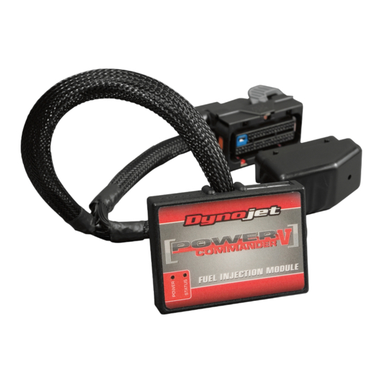
Power Commander
1
USB Cable
1
CD-ROM
1
Installation Guide
2
Power Commander Decals
2
Dynojet Decals
2
Velcro
1
Alcohol swab
the ignition MUst be tUrned
off before instaLLation!
You Can also download the
Power Commander software and
latest maPs from our web site at:
www.powercommander.com
2009 Victory Vision models PCV - 1
Advertisement

Related Manuals for Dynojet POWER COMMANDER V


Summary of Contents for Dynojet POWER COMMANDER V
- Page 1 CD-ROM Installation Guide i n s t a l l a t i o n i n s t r u c t i o n s Power Commander Decals Dynojet Decals Velcro Alcohol swab the ignition MUst be tUrned...
-
Page 2: Usb Connection
Do not connect anything to this port unless wire into the hole of the PCV until is stops and then instructed to do so by Dynojet. It is used to tighten the screw. Make sure to reinstall the rubber transfer crank trigger data from one module to plug. - Page 3 fig.a Remove the seat. Remove Remove both sidecovers (Fig. A). fig.b Install the PCV on the right side of the motorcycle using the supplied velcro. Make sure to clean both surfaces with the alcohol swab before attaching (Fig. B). Route the PCV harness to the left side of the bike. Keep the PCV harness as close to the frame as possible (Fig.
- Page 4 fig.d Locate the stock wiring harness at the rear injector (Fig. D). Remove the RED clip and unplug the injector connector. fig.e PCV connector Plug the YELLOW colored wires from the PCV in-line of the stock wiring harness and fuel injector (Fig. E) Repeat steps 7&8 for the front injector using the ORANGE colored wires from the PCV.
- Page 5 fig.g Unplug the stock wiring harness from the Ignition coil (Fig. G). fig.h Plug the PCV wiring harness in-line of the stock wiring harness and Ignition coil (Fig. H). fig.J Locate the Throttle Position Sensor wiring harness on the left hand side of the throttle bodies.
- Page 6 fig.K Locate the crank pickup coil connector on the right hand side of the bike near the rear shock (Fig. K). This is a BLACK 3 pin connector Unplug Unplug this connector. fig.L Plug the PCV harness in-line of the stock wiring harness and crank pickup coil connector (Fig.
Need help?
Do you have a question about the POWER COMMANDER V and is the answer not in the manual?
Questions and answers