Dynojet Power Commander V Installation Instructions Manual
Fuel and ignition controller for arctic cat wildcat 2012; arctic cat wildcat 2013; arctic cat wildcat 2014
Hide thumbs
Also See for Power Commander V:
- Installation instructions and owner's manuals (9 pages) ,
- Installation instructions manual (9 pages) ,
- Installation manual (9 pages)
Advertisement
Quick Links
2012-2014 Arctic Cat Wildcat
Fuel and Ignition Controller
I n s t a l l a t i o n I n s t r u c t i o n s
PLEASE READ ALL DIRECTIONS BEFORE STARTING INSTALLATION
I11-012.01
www.powercommander.com
2191 Mendenhall Drive North Las Vegas, NV 89081 (800) 992-4993 www.powercommander.com
PARTS LIST
1
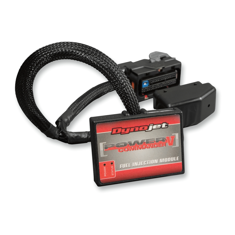
Power Commander
1
USB Cable
1
Installation Guide
2
Power Commander Decals
2
Dynojet Decals
2
Velcro Strips
1
Alcohol Swab
2
Zip Ties
THE IGNITION MUST BE TURNED
OFF BEFORE INSTALLATION!
YOU CAN ALSO DOWNLOAD THE
POWER COMMANDER SOFTWARE AND
LATEST MAPS FROM OUR WEB SITE AT:
www.powercommander.com
2012-2014 Arctic Cat Wildcat - PCV - 1
Advertisement

Related Manuals for Dynojet Power Commander V


Summary of Contents for Dynojet Power Commander V
- Page 1 Installation Guide Fuel and Ignition Controller Power Commander Decals I n s t a l l a t i o n I n s t r u c t i o n s Dynojet Decals Velcro Strips Alcohol Swab Zip Ties...
-
Page 2: Usb Connection
2. Using a 22-24 gauge wire, strip about 10mm from its end. instructed to do so by Dynojet. It is used to transfer crank trigger data from one module to 3. Push the wire into the hole of the PCV until it another. - Page 3 FIG.A remove Remove the drivers seat. Remove the panel behind the drivers seat as shown in Figure A. FIG.B remove Remove the cover over the center console as shown in Figure B. FIG.C Using the supplied velcro, secure the PCV to the top of the battery as shown in Figure C.
- Page 4 FIG.D Route the PCV harness down the back side of the battery, go underneath the frame crossover, and up the inside of the aluminum panel as shown in Figure D. Using the supplied zip ties, secure the PCV wiring harness to the frame. Make sure the harness does not interfere with the drive shaft.
- Page 5 FIG.G coil Locate the front ignition coil on the rear of the firewall in front of the engine as shown in Figure G. FIG.H Attach the connectors from the PCV harness with the green paired wires to the stock front coil and stock wiring harness as shown in Figure H. FIG.I Unplug the stock wiring harness from the throttle position sensor.
- Page 6 FIG.J Unplug the stock wiring harness from the rear fuel injector as shown in Figure J. FIG.K stock Attach the connectors with the yellow colored wires from the PCV harness to the rear fuel injector and stock harness as shown in Figure K. FIG.L Locate the ignition coil connector for the rear cylinder below the base of the radiator as shown in Figure L.
- Page 7 FIG.M Attach the connectors from the PCV harness with the blue paired wires to the stock rear coil and the stock harness as shown in Figure M. FIG.N Locate the 2-pin crank sensor at the bottom of the engine on the left hand side near the shift linkage.
Need help?
Do you have a question about the Power Commander V and is the answer not in the manual?
Questions and answers