Dynojet POWER COMMANDER V Installation Instructions Manual
For harley davidson street 500 2015
Hide thumbs
Also See for POWER COMMANDER V:
- Installation instructions and owner's manuals (9 pages) ,
- Installation instructions manual (9 pages) ,
- Installation manual (9 pages)
Advertisement
Table of Contents
2015 Harley Davidson Street 500
I n s t a l l a t i o n I n s t r u c t i o n s
PLEASE READ ALL DIRECTIONS BEFORE STARTING INSTALLATION
I15-012
www.powercommander.com
2191 Mendenhall Drive North Las Vegas, NV 89081 (800) 992-4993 www.powercommander.com
PARTS LIST
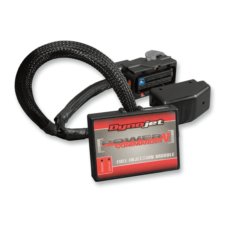
1
Power Commander
1
USB Cable
1
Installation Guide
2
Power Commander Decals
2
Dynojet Decals
2
Dual Lock Velcro strips
1
Alcohol swab
1
O2 Optimizer (front)
1
O2 Optimizer (rear)
THE IGNITION MUST BE TURNED
OFF BEFORE INSTALLATION!
THE LATEST POWER COMMANDER
SOFTWARE AND MAP FILES CAN BE
DOWNLOADED FROM OUR WEB SITE AT:
www.powercommander.com
2015 Harley Davidson Street 500 - PCV - 1
Advertisement
Table of Contents

Subscribe to Our Youtube Channel
Related Manuals for Dynojet POWER COMMANDER V


Summary of Contents for Dynojet POWER COMMANDER V
- Page 1 PARTS LIST Power Commander USB Cable Installation Guide 2015 Harley Davidson Street 500 Power Commander Decals Dynojet Decals I n s t a l l a t i o n I n s t r u c t i o n s Dual Lock Velcro strips Alcohol swab O2 Optimizer (front) O2 Optimizer (rear)
- Page 2 POWER COMMANDER V INPUT ACCESSORY GUIDE ACCESSORY INPUTS Map - (Input 1 or 2) The PCV has the ability to hold 2 different base maps. You can switch on the fly between these two base maps when you hook up a switch to the MAP inputs. You can use any open/close type switch. The polarity USB CONNECTION of the wires is not important. When using the Autotune kit one position will hold a base map and the other position will let you activate the learning mode. When the switch is “CLOSED” Autotune will be activated. (Set to Switch Input #1 by default.) Shifter- (Input 1 or 2) Used for clutch-less full throttle upshifts. Insert the wires from the Dynojet quickshifter into either INPUT 1 or INPUT 2. The polarity of the wires is not important. (Set ANALOG to Switch Input #2 by default.) SPEED Speed- Not needed on Harley applications as the EXPANSION PORTS 1 & 2 INPUT 2 (Grnd)
- Page 3 FIG.A Remove the seat and the left and right hand side covers. Using the supplied Dual Lock Velcro, secure the PCV module to the rear fender under the seat (Fig. A). Use the supplied alcohol swab to clean both surfaces prior to applying the Velcro adhesive. PCV Harness Route the wiring harness forward toward the bike’s ECM. FIG.B Unplug both of the stock connector’s from the bike’s ECM (Fig. B). Unplug Unplug FIG.C Plug the PCV wiring harness in-line of the bike’s ECM and both of the stock wiring harness connectors for the ECM (Fig. C). Keep the extra set of connectors laying as low and flat as possible. Use zip ties to secure the wiring and connectors if necessary.
- Page 4 FIG.D Locate and unplug the stock connector for the bike’s rear cylinder O2 sensor (Fig. D). This is a BLACK 4-pin connector located behind the left hand side cover. You can trace the cable from the rear O2 sensor to this connector. FIG.E Plug the supplied BLACK O2 Optimizer into the bike’s wiring harness in-place of the stock O2 sensor (Fig. E). There is a BLACK O2 Optimizer (rear) and a WHITE O2 Optimizer (front) O2 Optimizer in the kit.
- Page 5 FIG.G Plug the supplied WHITE O2 Optimizer into the bike’s wiring harness in-place of the stock O2 sensor (Fig. G). There is a BLACK O2 Optimizer (rear) and a WHITE O2 Optimizer (front) in the kit. They are indexed so they can NOT be connected incorrectly. The stock O2 sensor will no longer be used. It can be removed from the exhaust if desired and if you have a way to plug the hole left in the exhaust.
- Page 6 FIG.K 15 Store the Auto-tune module under the seat temporarily. Connect the O2 sensor cables to the Auto-tune module as shown in Figure K. Be sure to connect the front cylinder sensor cable to AT sensor input #1. Likewise, the rear cylinder sensor cable must go to AT sensor input #2. FIG.L 16 Use the supplied CAN link cable to connect either Auto-tune module expansion port to either PCV module expansion port. It does not matter which ports are used. 17 Install the supplied CAN termination plug into the open port of the Auto-tune module (Fig. L). This is a small BLACK hard plastic connector provided in the Auto-tune kit (PN: 76423025).
Need help?
Do you have a question about the POWER COMMANDER V and is the answer not in the manual?
Questions and answers