Dinolift DINO 260XTD Operating Instructions Manual
Boom lift
Hide thumbs
Also See for DINO 260XTD:
- Operating instructions manual (105 pages) ,
- Maintenance instructions manual (79 pages)

Subscribe to Our Youtube Channel
Related Manuals for Dinolift DINO 260XTD


Summary of Contents for Dinolift DINO 260XTD
- Page 1 OPERATING INSTRUCTIONS DINO 260XTD Manufacturer: Dealer: Dinolift Oy Raikkolantie 145 FI-32210 LOIMAA Tel. + 358 20 1772 400 info@dinolift.com www.dinolift.com...
- Page 3 TRANSLATION OF THE ORIGINAL INSTRUCTIONS Valid from serial number 260XTD 26419 -...
-
Page 4: Table Of Contents
Operating instructions • DINO 260XTD CONTENTS TO THE OPERATOR ....................6 1.1. OVERVIEW OF THE UNIT .................. 7 1.2. INTENDED USE OF THE WORK PLATFORM ........... 7 TECHNICAL SPECIFICATIONS ................. 8 2.1. DIMENSION DRAWING ..................10 2.2. REACH DIAGRAM .................... 11 2.3. - Page 5 5.3. IN CASE OF EMERGENCY ................48 5.3.1. When at risk of losing the stability ................48 5.3.2. In case of overloading ....................48 5.3.3. In case the power supply is interrupted ............... 48 5.3.4. In case of malfunction, when even the emergency descent system is not operational 50 INSTRUCTIONS FOR FAULT-FINDING ..............
-
Page 6: To The Operator
Dinolift Oy is constantly developing its products. For this reason, the contents of this manual DANGER might not always be in full compliance with the most recent version of the product. Dinolift Oy reserves the right to modify the product without prior notice. Dinolift Oy assumes no liability for any problems caused by changed or missing data or mistakes in this manual. -
Page 7: Overview Of The Unit
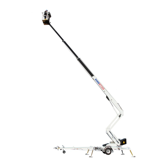
1.1. OVERVIEW OF THE UNIT This unit is a trailer mounted, towable aerial work platform. It is an aerial work platform, which complies with the EN280 type 1, where travelling is only allowed with the platform in transport configuration. For the operation the lift shall be supported by its hydraulic outriggers, extended so that the wheels of the trailer lift off the ground. -
Page 8: Technical Specifications
Operating instructions • DINO 260XTD TECHNICAL SPECIFICATIONS 260XTD Max. working height 26,0 m Max. platform height 24,0 m Max. outreach 11,7 m Boom rotation continuous Platform rotation 90° Turn area refer to the reach diagram Support width 4,40 m Transport width... - Page 9 Optional engines Hatz 1B30 EPA / CARB Tier 4 Final Fuel Diesel Net output 4.6 kW (6.2 hp)/ 3000 rpm Oil volume 1.1 l Sound pressure level 101 dB Whole-body vibration < 0,5 m/s2...
-
Page 10: Dimension Drawing
Operating instructions • DINO 260XTD 2.1. DIMENSION DRAWING... -
Page 11: Reach Diagram
2.2. REACH DIAGRAM... -
Page 12: Example Of The Machine's Nameplate
Operating instructions • DINO 260XTD 2.3. EXAMPLE OF THE MACHINE’S NAMEPLATE The name of the manufacturer, and the production number and serial number of the machine have been marked on the nameplate as shown in the picture below. DINO Type... -
Page 13: Example Of Eu Declaration Of Conformity
Dinolift Oy Raikkolantie 145 FI-32210 Loimaa, FINLAND declares that DINO 260XTD Aerial Work Platform no YGCD260XTH0026498 conforms to the provisions of the Machine Directive 2006/42/EC as well as the national decree (VNA 400/2008), through which they have been brought into effect The inspection in accordance with Annex IX to the directive 2006/42/EC has been carried out by the notified body no. -
Page 14: Sample Of Inspection Protocol For The Access Platform
Operating instructions • DINO 260XTD 2.5. SAMPLE OF INSPECTION PROTOCOL FOR THE ACCESS PLATFORM TEST CERTIFICATE DATE: START-UP TESTS: Inspection place: Dinolift Oy Inspector's signature: BASIC INFORMATION Manufacturer: Dinolift OY Place of manufacture: Finland Address: Raikkolantie 145 32210 LOIMAA Importer:... - Page 15 E. SAFETY AND CONTROL DEVICES F. SAFETY FEATURES 1. Safety limit switches 1. Prevention of unauthorized use 2. Sound signal 2. Locking device, covers and guards 3. Emergency descent system 3. Prevention of lifting 4. Protection of controls 4. Prevention of opening of support 5.
-
Page 16: Safety
Operating instructions • DINO 260XTD SAFETY All the essential safety instructions and warnings, relevant to transport, use and maintenance of the lift, are described in this chapter. DANGER Failure to observe these instructions and safety regulations may cause a severe injury or WARNING even death. - Page 17 TRANSFERS Observe the maximum allowed gradient when transferring the lift. During transfer in rough terrain, always try to position yourself higher than the machine. Beware of fixed or moving obstacles in the terrain or near the lift while driving. Make sure that you have a clear view of the driving path.
- Page 18 Operating instructions • DINO 260XTD LIFTING AND WORKING ON THE PLATFORM Never exceed the maximum number of persons, maximal loading or lateral force, allowed for the lift. Never add load onto the platform while in the upper position. Before operating, always ensure that the safety devices and the emergency descent system are in working order.
- Page 19 OPERATING CONDITIONS The weather conditions, such as wind, visibility and rain, must always be taken into account so that these will not adversely affect the safe performance of the lifting operations. The use of the lift is prohibited, if the temperature drops under -20 °C or the wind speed exceeds 12.5 m/s Wind speed ( m/s) Conditions on land...
-
Page 20: Safety-Related Notifications
Operating instructions • DINO 260XTD 3.2. SAFETY-RELATED NOTIFICATIONS The following safety alert symbols and safety signal words are used in this manual. Observe all the safety instructions that follow these symbols, in order to avoid dangerous situations and personal injuries. -
Page 21: Safety Devices
3.3. SAFETY DEVICES 1. Supervision of transport position of the boom The safety limit switch RK3 prevents the operation of the outriggers and the driving device when the boom is not resting on the transport support. The switch is located on the tow-bar at the transport support. - Page 22 Operating instructions • DINO 260XTD The green light in the control centre on the platform is lit, when the platform is within the allowed operating range. The reach limit switch RK4 will stop the movements, which impair the stability of the lift (extending the telescope and lowering the boom), at a predetermined position.
- Page 23 5. Supervision of the telescope chain The extension chains for the telescope are doubled. RK15 If the load-bearing chain slackens or breaks, the doubling chain prevents the movements of the telescope, and the safety switch RK7/RK15 breaks the emergency stop circuit. A - A ~32 mm DOUBLING CHAIN...
- Page 24 Operating instructions • DINO 260XTD 7. Safety devices for hose rupture All the load-bearing cylinders are equipped with valves for rupture or leak in the hydraulic system, which prevent the load from falling. Prevent the inching of the Outrigger cylinders Lock valves outriggers in either direction.
-
Page 25: Structure And Functions Of The Work Platform
STRUCTURE AND FUNCTIONS OF THE WORK PLATFORM The denominations of the machine’s essential parts and concepts, which are used later in these instructions, are described on the following pages. 4.1. STRUCTURE OF THE WORK PLATFORM Levelling cylinder of the platform (slave) Platform Boom extension 4 Boom extension 3... -
Page 26: Functions Of The Work Platform
Operating instructions • DINO 260XTD 4.2. FUNCTIONS OF THE WORK PLATFORM Turn counter- clockwise Left Drive direction Right Turn clockwise Levelling platform Lifting/ lowering the boom Lifting/ lowering the articulated arms Basket Turning the boom turning... -
Page 27: Operating Controls For The Functions
4.3. OPERATING CONTROLS FOR THE FUNCTIONS 4.3.1. Operating controls in the chassis control centre LCB Selector switch Emergency stop Start button for emergency descent Start and stop switches for the engine system Selection of boom speed Pushbutton for retracting the telescope Choke Lever switch for turning Signal light for safety device (RK5) -
Page 28: Operating The Support Outriggers From The Chassis Panel
Operating instructions • DINO 260XTD 4.3.2. Operating the support outriggers from the chassis panel Startbutton for the battery-operated pump Lifting and lowering the support outrigger 1 Lifting and lowering the support outrigger 2 Lifting and lowering the support outrigger 3... -
Page 29: Operating Controls In The Platform Control Centre Ucb
4.3.3. Operating controls in the platform control centre UCB Close the cover of the chassis control centre before operating the controls on the platform. The cover must not be locked while the lift is in operation. JSL Joystick, left JSR Joystick, right PR Socket outlet 230 V S7 Activation pedal 1. - Page 30 Operating instructions • DINO 260XTD X= -0,5º Y= 1,0º 3CB3090 Start and stop switches for the engine Emergency stop Start button for the emergency descent S13 Turning the platform system S14 Choke S32 Pushbutton for retracting the telescope S33 Lifting and lowering the support outrigger 1...
-
Page 31: Automatic Levelling And Electric Control Of The Driving Device - Dcb Centre (Option)
4.3.4. Automatic levelling and electric control of the driving device – DCB centre (option) 45-48 Lever switch for driving, right (to the Lever switch for automatic levelling front-rear) Lever switch for driving, left (to the front-rear) 50 Emergency stop Depressing the driving device rollers (option) 51 Light for automatic levelling 45-48 Lever switches for outriggers 1-4... -
Page 32: Operating Instructions
DANGER Operating instructions • DINO 260XTD WARNING OPERATING INSTRUCTIONS CAUTION 5.1. START-UP NOTICE Before operating the lift, perform all daily maintenance measures listed in the maintenance schedule. The operator must do a worksite inspection and daily maintenance: • at the beginning of each workday •... -
Page 33: Positioning The Lift
5.1.2. Positioning the lift 1. make sure that the ground is even and hard enough to support the lift in a steady, level position. Max. ground pressure Soil material Density kg/cm² (N/cm²) Gravel High density 6 (59) Medium density 4 (39) Loose 2 (20) Sand... -
Page 34: Starting The Machine
Operating instructions • DINO 260XTD 5.1.3. Starting the machine 1. Ensure that the main switch BMS is switched on. The switch is located above the lower control centre LCB. 2. Switch on the power via the switch Q1. POWERED BY COMBUSTION ENGINE 3. - Page 35 ELECTRIC MOTOR • For maximum out of the electric motor the voltage must 230 VAC (-10%/ +6%), and the frequency must be 50 Hz (the length of the connecting cable has some effect). • 16A fuse. Starting the electric motor 1.
-
Page 36: Supporting The Lift
Operating instructions • DINO 260XTD 5.1.4. Supporting the lift The support outriggers may only be operated, while the boom is resting on the support. Kpl/kone When operating the outriggers from the chassis control centre: VILAKONE OY Piirustuksen numero Revisio Ohjetarra, joystick 41603606 1. - Page 37 DANGER Always check that the lift is standing in a horizontal position. Readjust manually, if necessary. WARNING Lifting the outriggers to the transport position using the automatic levelling 5. Press the pedal. 6. Depress the right-hand side of the rocker switch on the left joystick in order to lift the CAUTION outriggers to the transport position.
-
Page 38: Operation
Operating instructions • DINO 260XTD DANGER 5.2. OPERATION WARNING Carry out all the daily maintenance routines and inspections in accordance with the CAUTION maintenance instructions before operating the lift. Failure to check the safety devices may cause a serious injury or make the consequences of an accident worse. -
Page 39: Operating The Lift From The Platform Control Centre
If the lift is operated from the chassis control centre, the speed of the boom movements cannot be adjusted continually using the control levers. 5.2.2. Operating the lift from the platform control centre DANGER Risk of falling! Wear a safety harness while on the platform, and WARNING fix it to the point marked for them. - Page 40 Operating instructions • DINO 260XTD is monitored by the safety limit switches RK4 and RK5, which are located under the protecting cover • The limit switches must not be adjusted or modified. The inspection and adjustment may only be carried out by an authorized serviceman.
-
Page 41: Special Instructions For Winter Use
CAUTION NOTICE Do not damage the tow-bar jockey wheel while lowering the platform to the transport position! When leaving the lift • drive the lift to a safe position, preferably to the transport position • switch off the power unit •... -
Page 42: Transferring The Lift
Operating instructions • DINO 260XTD 5.3. TRANSFERRING THE LIFT The lift can be transfered by towing or using its own driving device. The lift may only be moved in the transport position. No persons or load are allowed on the platform during the transportation. -
Page 43: Using The Driving Device
5.3.2. Using the driving device The hydraulic driving device is intended for moving the lift within the work area if the towing vehicle cannot be used. If the terrain is rough, use the remote control panel or a towing vehicle. When using the remote control panel, always try to position yourself higher than the machine in the terrain. - Page 44 Operating instructions • DINO 260XTD After the driving 1. Apply the parking brake 2. Disconnect the driving device from the tyre using the switch S48 in the chassis control panel. On a slope: 1. When driving on a slope, the tow-bar must always point towards the descent. Never drive with the driving device with the tow-bar pointing towards the ascent.
-
Page 45: Towing The Lift
5.3.3. Towing the lift Connecting to the towing vehicle 1. Lift up and push forward (in the driving direction) the handle of the ball-coupling. Now the ball-coupling is released. 2. Press the ball-coupling onto the towball using only a little force. The connection and locking take place automatically. -
Page 46: Lifting The Device
Operating instructions • DINO 260XTD 5.3.4. Lifting the device The device can be lifted using the lugs shown in the picture. The lifting lugs are located symmetrically on both sides of the lift. During lifting the aerial work platform must be in the transport position. Remove all loose material from the top of the frame structures and the work platform before lifting. -
Page 47: Long-Term Storage
DANGER WARNING 5.4. LONG-TERM STORAGE Clean the machine carefully, lubricate it and apply protective grease to it before putting it into storage for a longer period of time (see point “Lubrication plan”). Repeat the cleaning and CAUTION lubrication procedures when you resume the operation. NOTICE If you leave the lift standing for a longer period of time, for example over the winter, we recommend propping it up to release any load from the wheels. -
Page 48: In Case Of Emergency
Operating instructions • DINO 260XTD 5.3. IN CASE OF EMERGENCY 5.3.1. When at risk of losing the stability Reduced stability can be caused by a fault in the lift, the wind or other lateral force, collapse of the standing base or negligence in providing sufficient support. In most cases one sign of reduced stability is the inclination of the lift. - Page 49 When the emergency descent system is operated from the platform control centre, the telescope automatically moves inward. As soon as the telescope reaches its inner position, the limit switch RK8 switches the function to the descent movement of the boom and the articulated arms.
-
Page 50: In Case Of Malfunction, When Even The Emergency Descent System Is Not Operational
Operating instructions • DINO 260XTD 5.3.4. In case of malfunction, when even the emergency descent system is not operational If not even the emergency system is working, try to warn other personnel present on the site or call for more help. When help arrives, try to •... -
Page 51: Instructions For Fault-Finding
INSTRUCTIONS FOR FAULT-FINDING FAULT REMEDY 1. No voltage supply to the control centre Main switch turned off. Turn the main switch on. Timer card cannot be activated. Check that the key-switch is in position 1. 2. The electric motor does not start Turn the key-switch to the desired operating Key-switch is in the wrong position. - Page 52 Operating instructions • DINO 260XTD FAULT REMEDY 7. Outriggers do not move The boom is not resting on the transport support. Drive the boom onto the transport support. The selector switch is in the wrong position. Turn the selector switch to the correct position.
- Page 53 NOTES...
- Page 54 Operating instructions • DINO 260XTD NOTES...
-
Page 55: Maintenance Schedule
MAINTENANCE SCHEDULE Service Service interval Service person Instructed operating Daily Operator instructions every month/100 maintenance Competent person who is familiar with the lift hours* instructions DANGER every 6 months/400 maintenance Competent person who is familiar with the lift hours* instructions every 12 Technical specialist, who is well familiar with the maintenance... - Page 56 Operating instructions • DINO 260XTD Maintenance measures Condition of brakes Axle and suspension Driving device Lights Hydraulic oils Hydraulic hoses, pipe and conections Condition and attachment of battery and wiring Hydraulic pressure Condition and attachment of safety devices Operation of safety devices (limit switches)
-
Page 57: Schedule For Inspections Required By The Authorities
7.1. SCHEDULE FOR INSPECTIONS REQUIRED BY THE AUTHORITIES The inspections must be performed in accordance with local and national regulations, in accordance with the legislation and standards. The lift must be subjected to a start-up inspection before it is used for the first time and before starting it up the first time after a major repair or modification work. -
Page 58: Lubrication Plan
Operating instructions • DINO 260XTD 7.2. LUBRICATION PLAN... -
Page 59: Routine Maintenance During Operation
ROUTINE MAINTENANCE DURING OPERATION The maintenance operations, that are the responsibility of the operator, are described in this chapter. The more demanding maintenance operations that require special skills, special tools or specific measurements and adjustment values are instructed in the separate Maintenance Instructions. -
Page 60: Instructions For Daily Maintenance And Inspections
Operating instructions • DINO 260XTD 8.1. INSTRUCTIONS FOR DAILY MAINTENANCE AND INSPECTIONS 8.1.1. Check the condition of chassis, the boom and the work platform Check visually the condition of the access routes, the work platform, the platform gate and the handrails. -
Page 61: Check The Operation Of The Safety Limit Switches
8.1.6. Check the operation of the safety limit switches Test the operation of the safety limit switches that prevent the movements of the boom and the outriggers as follows: 1. The lift is in the transport position with the outriggers in the upper position, and the driving device connected. - Page 62 Operating instructions • DINO 260XTD BLANK...
-
Page 63: Change Of Owner
If you have purchased a used DINO lift from some other than the manufacturer, please post your details to the manufacturer using the form on this page, and send it to: info@dinolift.com This information makes it possible for us to provide you with the safety bulletins and other campaigns relevant to your machine. - Page 64 Operating instructions • DINO 260XTD NOTES...
- Page 65 NOTES...
Need help?
Do you have a question about the DINO 260XTD and is the answer not in the manual?
Questions and answers