Dinolift DINO 260XTD Operating Instructions Manual
Hide thumbs
Also See for DINO 260XTD:
- Operating instructions manual (65 pages) ,
- Maintenance instructions manual (79 pages)

Related Manuals for Dinolift DINO 260XTD


Summary of Contents for Dinolift DINO 260XTD
- Page 1 DINO ® 260XTD OPERATING INSTRUCTIONS Manufacturer: ® Raikkolantie 145 FI-32210 LOIMAA T. +358 2 762 5900 F. +358 2 762 7160 dino@dinolift.com www.dinolift.com Dealer:...
- Page 2 DINO 260XTD...
- Page 3 DINO 260XTD ORIGINAL OPERATING INSTRUCTIONS 26323 Valid from serial number...
-
Page 4: Table Of Contents
DINO 260XTD TABLE OF CONTENTS EU DECLARATION OF CONFORMITY ..................6 REACH DIAGRAM...........................7 DIMENSION DRAWING........................8 TECHNICAL SPECIFICATION .....................9 ’ ..................9 XAMPLE OF THE MACHINE S NAMEPLATE ..................10 ENERAL DESCRIPTION OF THE MACHINE ’ ................10 ESCRIPTION OF THE MACHINE S INTENDED USE GENERAL SAFETY REGULATIONS ..................11... - Page 5 DINO 260XTD 17.3 WHEEL BRAKES AND BEARINGS..................42 17.4 LUBRICATION PLAN ......................45 17.5 LONG-TERM STORAGE......................46 17.6 LOAD HOLDING AND LOAD REGULATION VALVES............47 17.7 LEVELLING SYSTEM OF THE PLATFORM ...............49 17.8 REGULAR SERVICING ......................50 17.8.1 TESTING THE OUTREACH LIMIT SWITCH..............55 17.8.2 SETTING OF THE OUTREACH LIMIT SWITCH AND THE OVERLOAD LIMIT SWITCH 57 INSPECTION INSTRUCTIONS....................61...
-
Page 6: Eu Declaration Of Conformity
DINO 260XTD 1 EU Declaration of Conformity EU Declaration of Conformity Dinolift Oy Raikkolantie 145 FI-32210 Loimaa, which has authorised the Chief Engineer Mr. Seppo Kopu to draw up the Technical Construction File declares that DINO 260 XTD Access Platform no YGC D260XT X X XXXXX... -
Page 7: Reach Diagram
DINO 260XTD 2 REACH DIAGRAM... -
Page 8: Dimension Drawing
DINO 260XTD 3 DIMENSION DRAWING... -
Page 9: Technical Specification
DINO 260XTD 4 TECHNICAL SPECIFICATION Max. working height 26.0 m Max. platform height 24.0 m Max. outreach 11.7 m Boom rotation continuous Platform rotation 90° Turn area refer to reach diagram Support width 4.40 m Transport width 2.05 m Transport length 8.11 m... -
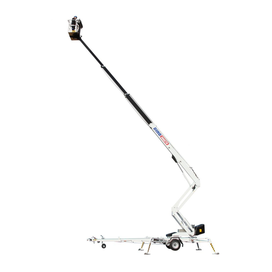
Page 10: General Description Of The Machine
DINO 260XTD 4.2 General description of the machine The denominations of the machine’s essential parts and concepts, which are used later in these instructions, are described on this page. 4.3 Description of the machine’s intended use The Access Platform is exclusively intended for transferring people and tools and acting as a work platform to the limit of its load-bearing capacity and reach (refer to the table of Technical Specifications and Reach Diagram). -
Page 11: General Safety Regulations
DINO 260XTD 5 GENERAL SAFETY REGULATIONS Make yourself familiar with these operation instructions before using the lift! Keep these operating instructions in the place reserved for them. Make sure that all users of the lift are familiar with these instructions. - Page 12 DINO 260XTD Do not use ladders, steps or other similar equipment on the platform. Never throw any objects from the platform. The lift must not be used for transferring goods or persons between different floors or working levels. Never disable the operation of any safety device.
-
Page 13: Instructions For Safe Operation
DINO 260XTD 5.1 !! Instructions for safe operation! Use a safety harness while on the platform. Use hearing protectors when operating the power unit (optional) from the chassis panel. Sound pressure level 82 dB. Never load the platform while in the upper position. -
Page 14: Inspections
DINO 260XTD Never use a lift alone. Make sure, there is always someone on the ground, who can call for help in case of an emergency. INSPECTIONS A thorough inspection of the lift must be carried out at least once every twelve (12) months. -
Page 15: Worksite Inspection
DINO 260XTD 7 WORKSITE INSPECTION 1. General information Is the lift suited for the intended job? Is the performance of the lift sufficient for the job? (reach, loadability etc.) Is the position of the lift safe? Is the lighting on the worksite sufficient? 2. -
Page 16: Operation Of Safety Devices
DINO 260XTD OPERATION OF SAFETY DEVICES... - Page 17 DINO 260XTD 1. Lifting the boom (Fig. A) The safety limit switch RK3 prevents the operation of the outriggers and the driving device when the boom does not rest on the transport support. The switch is located on the tow-bar at the transport support.
-
Page 18: Operating Controls
DINO 260XTD 9 OPERATING CONTROLS 9.1 OPERATING CONTROLS ON THE CHASSIS CONTROL PANEL Fuse for the socket outlet on the platform Signal light for the outreach control safety limit switch Selector switch for the operating location Emergency stop button Start and stop switches for the combustion engine... -
Page 19: Operating Controls On The Platform
DINO 260XTD 9.2 OPERATING CONTROLS ON THE PLATFORM Close the cover of the chassis control panel before operating the platform controls. Display Signal light for the outrigger limit switches Alarm signal light Automatic fuse for turning the platform Start and stop switches for the combustion engine... - Page 20 DINO 260XTD 17. Control lever JSR (right) Boom up Driving to the front Turning the boom to the Turning the boom to right the left Curving to the left, to Curving to the the front and rear right, to the...
- Page 21 DINO 260XTD 19. Control lever JSL (left) Retracting the telescope 1. Automatic levelling 2. Outriggers up (optional) Lowering the Raising the articulated arms articulated arms Extending the telescope...
-
Page 22: Measures To Be Taken In Case Of Emergency/At Risk Of Losing The Stability
DINO 260XTD MEASURES TO BE TAKEN IN CASE OF EMERGENCY/AT RISK OF LOSING THE STABILITY Reduced stability can be caused by a fault in the lift, the wind or other lateral force, collapse of the standing base or negligence in providing sufficient support. In most cases one sign of reduced stability is the inclination of the lift. -
Page 23: Start-Up
DINO 260XTD Always check the condition of the emergency descent system battery before putting the lift into operation (see point "Using the chassis control panel"). 11 START-UP 11.1 Ground stability make sure that the ground is even and hard enough to support the lift in a steady level position... - Page 24 DINO 260XTD...
-
Page 25: Starting The Engine
DINO 260XTD 11.2 Starting the engine At first, make sure that the main battery switch is switched on. The main switch is located on top of the chassis control panel. Select the operating location using the switch Q1. Check the condition of the battery to ensure operation of the emergency descent system. The emergency descent unit must rotate at a fair speed as the emergency descent button is depressed. -
Page 26: Operating The Support Outriggers From The Chassis Panel
DINO 260XTD 11.3 Operating the support outriggers from the chassis panel The support outriggers may only be operated, while the boom is resting on the support. The support outriggers are operated using dedicated lever switches for each outrigger. 1. Turn the selector switch S47 to position 1 and keep it there as long as you operate the selected movement. -
Page 27: Operating The Support Outriggers From The Platform Panel
DINO 260XTD 11.4 Operating the support outriggers from the platform panel The support outriggers may only be operated, while the boom is resting on the support. The support outriggers are operated using dedicated lever switches for each outrigger. 1. Press the foot pedal. -
Page 28: Using The Chassis Control Panel
DINO 260XTD 6. Depress the right-hand side of the rocker switch on the left joystick in order to lift the outriggers to transport position. 11.5 Using the chassis control panel Select the chassis panel using the selector switch (Q1) for the operating location... -
Page 29: Using The Control Panel On The Platform
DINO 260XTD DO NOT DAMAGE THE TOW-BAR JOCKEY WHEEL! 11.6 Using the control panel on the platform once the foot pedal is depressed, the electric motor starts automatically as any of the movements is activated for operation powered by combustion engine, start the engine using the selector switch Adjust the engine speed to ¾... - Page 30 DINO 260XTD activate the foot pedal and drive the unit using the right-hand joystick (JSR) (see the operating diagram in point “Using the control panel on the platform”) do not drive the jockey wheel into obstacles or potholes after the driving apply the parking brake...
-
Page 31: Boom Movements From The Platform Panel
DINO 260XTD 11.8 Boom movements from the platform panel - select "driving from the platform" using the switch Q1 on the chassis control panel - activate the foot pedal as required, start the combustion engine in accordance with the instructions... -
Page 32: Test The Operation Of The Outreach Limit Switch Rk4
DINO 260XTD 11.10 Test the operation of the outreach limit switch RK4 platform load about 80 kg drive the boom to a horizontal position extend the telescope As the movement stops, the red light H2 shall flash, the buzzer on the platform shall buzz and the text "maximum outreach"... -
Page 33: Driving Instructions
DINO 260XTD 11.11 Driving instructions 1. Refer to the item "Daily inspections" in the task list for servicing. 2. With the boom slightly lifted and the telescope extended, make sure that the platform does not lower of itself while the operating controls are not being used. - Page 34 DINO 260XTD 6. Working a long time in the same position it is not necessary to let the engine run if the weather is warm and the platform is kept for a longer period of time in the same position...
-
Page 35: Emergency Descent System
DINO 260XTD 12 EMERGENCY DESCENT SYSTEM As a precaution against malfunction, the lift is equipped with a battery-operated emergency descent system. 1. Setup of the system battery 12V 44Ah battery charger hydraulic unit 12 VDC 2. Servicing the battery the system incorporates an automatic battery recharger with short circuit and overheat... - Page 36 DINO 260XTD Always check the condition of the emergency descent system before putting the lift into operation (see point "Using the chassis control panel"). Emergency descent operations from the chassis control panel You can use the emergency descent system for lifting the outriggers to the transport position and for disconnecting the drive rollers from the tyres.
-
Page 37: Special Instructions For Winter Use
DINO 260XTD 13 SPECIAL INSTRUCTIONS FOR WINTER USE the lowest allowed operating temperature of the lift is -20 °C. if the temperature is below zero, let the power unit run for a few minutes before starting the movements start with a few movements to warm-up oil in the cylinders and to ensure proper operation of the... -
Page 38: Preparing The Lift For Transport
DINO 260XTD 15 PREPARING THE LIFT FOR TRANSPORT 1. Apply the parking brake. 2. Retract the telescope boom completely. 3. Check that the platform is perpendicular to the boom. 4. Lower the boom/platform onto the transport support on the tow-bar. -
Page 39: Connection To The Towing Vehicle
DINO 260XTD CONNECTION TO THE TOWING VEHICLE 1. Lift up and push forward the ball-coupling handle (in the driving direction). Now the ball-coupling is released. 2. Press the ball-coupling onto the towball using only a little force. The hooking up and locking will take place automatically once the handle is lowered. -
Page 40: Instructions For Service And Maintenance
DINO 260XTD INSTRUCTIONS FOR SERVICE AND MAINTENANCE 17.1 GENERAL SERVICE INSTRUCTIONS carry out the servicing and inspection of the lift in accordance with the instructions when it comes to more demanding repair works turn to a specialist or contact the distributor or the... -
Page 41: Service And Inspection Instructions
DINO 260XTD 17.2 SERVICE AND INSPECTION INSTRUCTIONS 1. The first service after 20 hours of operation change the pressure and return filter elements adjust the brakes according to the instructions (see point "Wheel brakes and bearings") check the the wheel bolts for tightness after about 100 km of driving (325 Nm) 2. -
Page 42: Wheel Brakes And Bearings
DINO 260XTD 17.3 WHEEL BRAKES AND BEARINGS Adjustment of the brakes Jack up the lift until the wheels rise off the ground and support it in this position. Make sure that the wheels can rotate freely. The brake rods must be slack (with the handbrake released). - Page 43 DINO 260XTD Adjust the braking force with the nuts keeping the brake balancer perpendicular to the tow-bar so that both wheels will brake. ADJUSTMENT NUTS PERPENDICULAR Tightening the brake system too much causes overheating of the brakes during transportation and increases the required towing force.
- Page 44 DINO 260XTD Adjustment of the bearing clearance The wheel bearings are lubricated for life and do not require any service. (The bearings do not require any lubrication and they cannot be adjusted) Service intervals 500 km (running in) 5,000 km...
-
Page 45: Lubrication Plan
DINO 260XTD 17.4 LUBRICATION PLAN... -
Page 46: Long-Term Storage
DINO 260XTD EVERY 50 HOURS 1. Bearings of the safety device 2. Bearings of the outrigger cylinders 3. Bearings of the outriggers 4. Bearings of the outrigger foot plates 5. Bearings of the boom and the articulated arms 6. Bearings of the platform 7. -
Page 47: Load Holding And Load Regulation Valves
DINO 260XTD 17.6 LOAD HOLDING AND LOAD REGULATION VALVES... - Page 48 DINO 260XTD Check of operation 1. To check the tightness of the outrigger cylinder load holding valves measure the height position of the chassis from the floor separately at each outrigger. After a few minutes, measure the height again. 2. To check the tightness of the load regulation valves on the boom cylinder and the cylinders of the articulated arms drive the boom to a position in which its movement can be reliably measured.
-
Page 49: Levelling System Of The Platform
DINO 260XTD 17.7 LEVELLING SYSTEM OF THE PLATFORM A so-called Slave Cylinder System is applied for levelling of the platform: the slave cylinder under the platform is controlled by a master cylinder the platform keeps its level position only if the valves in the system are tight the levelling system comprises the following parts: 11. -
Page 50: Regular Servicing
DINO 260XTD 17.8 REGULAR SERVICING The lift shall be serviced regularly at intervals of 11 - 12 month. Under demanding conditions where moist, corrosive substances or corrosive climate may speed up the deterioration of the structure and induce malfunctions, the inspection must be performed more often and the influence of corrosion and malfunctions must be reduced by using appropriate protective means. - Page 51 DINO 260XTD never mix different oil sorts if required, top up hydraulic oil to the level with the upper edge of the level eye while the lift is in the transport position. NOTE! Do not spill oil into the environment.
- Page 52 DINO 260XTD 6. Inspection of the boom and the chassis extend the telescope and inspect the platform, its attachment, the articulated arms and the boom inspect the boom joints and play of the sliding pads, readjust if necessary. Lubricate the sliding...
- Page 53 DINO 260XTD 7. Check the overrun attachment of the overrun clearance condition of the towball-coupling condition of the locking device check that the overrun brake mechanism moves freely: stop the lift, as instructed (see point "Preparing the lift for transport")
- Page 54 DINO 260XTD 10. operation of the safety devices when controlled from the platform lift the boom from the transport support the outriggers must not operate in any position of the selector switch lift the boom and test the following: 1. operation of the emergency stop button 2.
-
Page 55: Testing The Outreach Limit Switch
DINO 260XTD 17.8.1 TESTING THE OUTREACH LIMIT SWITCH Put a carefully weighed load (80 kg) on the platform. Place it at a distance of 100 mm from the rear edge of the platform. drive to boom to a horizontal plane from the chassis control... - Page 56 DINO 260XTD TESTING THE OVERLOAD LIMIT SWITCHES the second safety limit switch (RK5) backs up if the outreach limit switch (RK4) fails disable the RK4 by connecting the terminals 9 and 30 inside the chassis control panel with a jumper lead Also connect the terminal 58 and the terminal SR3:X2 on the safety relay using a jumper lead.
-
Page 57: Setting Of The Outreach Limit Switch And The Overload Limit Switch
DINO 260XTD 17.8.2 SETTING OF THE OUTREACH LIMIT SWITCH AND THE OVERLOAD LIMIT SWITCH Always check the operation of both limit switches in connection with the service. put a load of 80 kg onto the platform drive the boom to a horizontal position... - Page 58 DINO 260XTD Adjustment method I: make sure that the RK5 with certainty will trip before the RK4 by adjusting the RK4 extend the boom and measure the length of one protruding part of the telescope extension (stroke) the measure shall be 2,350 mm ±50 mm.
- Page 59 DINO 260XTD 11. Measuring the pressure Connect the pressure gauge to the measuring point (indicated by the arrow). the max. pressure with warm (40 - 60 °C) oil is 20 -20,5 MPa (200 -205 bar) the turning pressure is 8 MPa (80 bar) if you have to readjust the pressure, secure the new setting with a seal.
- Page 60 DINO 260XTD 13. Warning stickers and adhesive tapes make sure all warning stickers and adhesive tapes are legible, replace if necessary 14. Inspect the brakes and the driving device remove the wheels clean the brake system and check the settings...
-
Page 61: Inspection Instructions
DINO 260XTD 18 INSPECTION INSTRUCTIONS All lifting equipment and lifting gear used at a construction site must always be inspected before use. The lifts and related lifting gear used on a work site shall be subjected to a regular maintenance inspection;... -
Page 62: Sample Of Inspection Protocol For The Access Platform
DINO 260XTD 18.2 SAMPLE OF INSPECTION PROTOCOL FOR THE ACCESS PLATFORM... - Page 63 DINO 260XTD...
-
Page 64: Daily Inspection (Start-Up Inspection)
DINO 260XTD 18.3 DAILY INSPECTION (START-UP INSPECTION) To be always performed at a new work site and in the beginning of every working day. The inspection is performed by the user. In the inspection attention shall be paid to the following... -
Page 65: Monthly Inspection (Maintenance Inspection)
DINO 260XTD 18.4 MONTHLY INSPECTION (MAINTENANCE INSPECTION) The inspection shall be performed by a person who is well familiar with the lift. Task list for inspection: perform the measures of the daily inspection check the attachment points of the boom and the platform... -
Page 66: Annual Inspection (Regular Inspection)
DINO 260XTD 18.5 ANNUAL INSPECTION (REGULAR INSPECTION) The inspection shall be performed by a skilled technician or an expert inspection body with documented evidence of competence (see point “Inspections”). In the inspection special attention has to be paid to the condition of the steel structures, the safety devices and the operating system. - Page 67 DINO 260XTD directional valves on the chassis check that the valves of the support outriggers and the driving device work properly and no movements are executed when the spools are in the neutral position electro-hydraulic rotary adaptor check the adaptor for tightness...
- Page 68 DINO 260XTD Check the condition of the gas springs check the condition of the master and slave cylinder bearings and pins and the locking of the pins check the condition of the boom joint check the bearing and the pin of the boom joint and the locking of the pin...
-
Page 69: Extraordinary Inspection
DINO 260XTD check the condition of the chassis general condition check the attachment of the tow-bar to the chassis check the condition of the overrun and its attachment to the chassis. check the axle and its attachment to the chassis... -
Page 70: Test Loading Instructions For Regular Inspection
DINO 260XTD 18.7 TEST LOADING INSTRUCTIONS FOR REGULAR INSPECTION 1. Place the lift on an even surface with good carrying capacity. Drive the outriggers to their lowest position (the minimum support width). 2. Turn the boom to the side from the tow-bar and lower it on the ground. -
Page 71: Fault Finding
DINO 260XTD FAULT FINDING FAULT REMEDY 1. No voltage supply to the control centre No voltage supply to the timer card. The main battery fuse F1 has blown, replace the fuse. Mains switch turned off, turn on the switch. The timer card cannot be activated. - Page 72 DINO 260XTD FAULT REMEDY 6. Disturbance of platform movements - only one of the movements is operational Irregular and indefinite malfunctions. Make sure that the hydraulic oil and the filter have been changed. Thoroughly clean the solenoid valve spools and housings (requires utmost cleanliness - not all contaminants can be spotted with the naked eye).
- Page 73 DINO 260XTD FAULT REMEDY 10. Boom cannot be lifted Refer to item 4. The solenoid valve is in the neutral or in the lowering position. Remedy as instructed above in conjunction with the seizure of the electric valve spool. The lift turns as the lifting movement is Solenoid valve is stuck in turning position.
- Page 74 DINO 260XTD FAULT REMEDY 14. Platform drifts forward Double load regulation valve on the rod side is Measures as above. leaking. 15. Support outriggers do not operate Boom does not rest on the transport support. Drive the boom onto the support.
- Page 75 DINO 260XTD FAULT REMEDY 19. Too low braking force Too much play in the brake system. Adjust the brake system (see point "Wheel brakes and bearings"). Brake linings not yet run-in. Pull the parking brake lever slightly and drive 2 - 3 kilometres.
- Page 76 DINO 260XTD FAULT REMEDY 25. Ball-coupling is not locked Inner parts of the ball-coupling dirty. Clean and lubricate. Tow-ball of the towing vehicle too large. Measure the tow-ball. According to DIN74058 the diameter of the ball must be max. 50 mm and min.
-
Page 77: Operation Of Electric Components
DINO 260XTD 20 OPERATION OF ELECTRIC COMPONENTS 20.1 MAIN CENTRE (PK), RELAYS K1: Control contactor for the motor (M1) K2: Auxiliary contactor for the emergency stop switch Switches on/off the mains supply (230VAC). K3: Sensor relay for AC feed. Enables operation of the electric motor, while the relay is active. -
Page 78: Main Centre (Lcb), Switches
DINO 260XTD Overloading of the boom: SR3 trips. The safety relay is automatically reset upon return to the normal outreach range. As the RK4 or the RK5 has failed: The safety relay SR3 trips as soon as the operating range for the RK5 has been exceeded. -
Page 79: Main Centre (Lcb), Other Items
DINO 260XTD 20.3 Main centre (LCB), other items E1: Thermo-relay for the engine M1. F1: Main battery switch (125A). F2: Control circuit main switch (10A). F3: Emergency stop circuit, power supply to safety relays, activation of the combustion engine recharge and turning of platform (10A). -
Page 80: Control Centre (Ucb), Relays
DINO 260XTD 20.4 Control centre (UCB), relays K14: Turning the platform to the left. The linear motor is controlled by means of a relay, the inductive limit switch RK9 limits the maximum turning angle by disconnecting the control voltage from the relay. -
Page 81: Control Centre (Ucb), Other Items
DINO 260XTD 20.6 Control centre (UCB), other items DSP Display, shows the alarm messages, the inclination sensor view and assists while the parameters are being adjusted (see separate instructions). F10: Power supply to the turning motor for the platform (5A, automatic). -
Page 82: Chassis, Other Items
DINO 260XTD MC50-10CCB: Bus module, control unit for the outriggers and the driving device as well as inlet unit for the outrigger limit switches. 20.9 Chassis, other items VVK: Fault current switch, disconnect the alternating current in the event of fault current. -
Page 83: Turning Device (Ru), Other Items
DINO 260XTD Slows down the lifting movement of the boom while approaching the maximum length of the lifting cylinder. 20.11 Turning device (RU), other items B1: Battery 12VDC 44Ah. Iida: Switch-off unit for the combustion engine, connects the ignition spool to earth. -
Page 84: Electric Diagram 26323
DINO 260XTD 21 ELECTRIC DIAGRAM 26323 >... - Page 85 DINO 260XTD...
- Page 86 DINO 260XTD...
- Page 87 DINO 260XTD...
- Page 88 DINO 260XTD...
- Page 89 DINO 260XTD...
- Page 90 DINO 260XTD...
- Page 91 DINO 260XTD...
- Page 92 DINO 260XTD...
- Page 93 DINO 260XTD...
- Page 94 DINO 260XTD...
- Page 95 DINO 260XTD...
- Page 96 DINO 260XTD...
- Page 97 DINO 260XTD...
- Page 98 DINO 260XTD...
- Page 99 DINO 260XTD...
- Page 100 DINO 260XTD...
- Page 101 DINO 260XTD...
- Page 102 DINO 260XTD...
-
Page 103: Hydraulic Components
DINO 260XTD 22 HYDRAULIC COMPONENTS 26209 and 26229> Ref. Part nr. Item Pcs. 47.828 Electric motor 47.2061 Hydraulic pump Combustion engine 47.892 (aggregate) Power unit (reserve power 47.2317 pack) 47.3003 Check valve 47.195 Pressure filter 47.2963 Solenoid valve 47.190 Breather plug 47.080... -
Page 104: Hydraulic Diagram
DINO 260XTD 23 HYDRAULIC DIAGRAM 26120 and 26122>... - Page 105 DINO 260XTD Notes...
Need help?
Do you have a question about the DINO 260XTD and is the answer not in the manual?
Questions and answers