Advertisement
Table of Contents
- 1 Table of Contents
- 2 Important Statement
- 3 Safety Precautions
- 4 Safe Notice for Drone Battery
- 5 Charging Instruction for Drone Battery
- 6 Check List before Flight
- 7 Instruction for Drone and Transmitter
- 8 Battery Installation
- 9 Pre-Flight Operation Instruction
- 10 Functions Introduction
- 11 To Know Your APP
- 12 Component Integration
- 13 Spare Parts
- 14 Troubleshooting Guide
- Download this manual
Advertisement
Table of Contents

Subscribe to Our Youtube Channel
Related Manuals for UDI R/C Discovery2


Summary of Contents for UDI R/C Discovery2
- Page 1 U818A Plus-W Operations Guide...
-
Page 2: Table Of Contents
www.udirc.com Catalog Important Statement Safety Precautions Safe Notice for Drone Battery Charging Instruction for Drone Battery Check List Before Flight Instruction for Drone and Transmitter Pre-flight Operation Instruction Functions Introduction To know your APP component integration Spare Parts Troubleshooting Guide... -
Page 3: Important Statement
www.udirc.com Important Statement Thank you for buying UDIRC's product. People who under 14 years old must not use the product. Please read this brochure carefully before using the product. You are regarded as accepting all content in this user manual when using this drone. This product is not an ordinary toy but a piece of complicated equipment which is integrated with professional knowledge by mechanic, electronic, air mechanics, high-frequency emission etc. -
Page 4: Safe Notice For Drone Battery
www.udirc.com (5) Safe operation Please operate the RC drone in accordance with your physical status and flying skill. Fatigue, listlessness and improper operation may increase the rate of accident. (6) Keep away from rotating parts Rotating parts like propellers or motors may cause serious injury and damage. Keep face and body away from rotating parts. -
Page 5: Charging Instruction For Drone Battery
www.udirc.com Charging Instruction for Drone Battery 1. Connect the drone battery with USB cable first and then choose one of the method as below picture shown to connect with USB plug. 2. The red USB indicator light keeps bright when charging. And the light turns green when fully charged. -
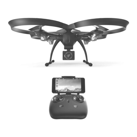
Page 6: Instruction For Drone And Transmitter
www.udirc.com Instruction for Drone and Transmitter Drone Front A Propeller B Propeller Clockwise Counterclockwise Drone cover housing Left Right B Propeller A Propeller Counterclockwise Clockwise Rear Front Front LED Front LED (Green) (Green) Rear LED Rear LED ( Red) ( Red) Power Switch Rear Specification... - Page 7 www.udirc.com Exploded View Name Name Name Drone Cover Housing Lamp hood Receiver board A propeller (Clockwise) B propeller(Counterclockwise) Power switch Motor upper holder A Motor upper holder B Receiver board bracket Gears Front LED board(Green) Power board Aluminum Spindle Motor holder Video adapter board Bearing Square carbon fiber tube...
- Page 8 www.udirc.com Transmitter Phone holder Power Switch Left Stick Right Stick (Throttle / Rudder) (Forward / Backward ) One button Take Off / Heading Hold Mode Landing / Emergency Stop Button High / Medium/Low Trimmer mode button Speed button Battery cover Brief Introduction for Button Functions Left Stick Move the Stick to forward / backward / left / right to fly the drone to up / down / turn left / turn right.
-
Page 9: Battery Installation
www.udirc.com Battery installation: Open the battery cover on the back side of the transmitter and put 4 alkaline batteries (AA, not included) into the box in accordance with electrode instructions, as picture 1,2 shown. 4*1.5V Alkaline Batteries Battery Cover Picture 1 Picture 2 1. -
Page 10: Pre-Flight Operation Instruction
www.udirc.com Pre-flight Operation Instruction Frequency Pairing 1. Turn on the transmitter switch (Picture 7) and the power indicator light flashes rapidly. Push the Left Stick all the way down to the lowest position and then release. The Left Stick will back to the middle position automatically. (Picture 8 / 9) The power indicator light flashes slowly, which indicates the transmitter is ready for frequency pairing. - Page 11 www.udirc.com Checklist before Flight 1. The camera is in front of the drone. Keep the drone front away from you. 2. Power on the drone and check the direction of the rotating propellers. The left front and right rear A propellers rotating clockwise while the right front and left rear B propellers rotating counterclockwise.
- Page 12 www.udirc.com Flying Control Notice: Every time before the drone take off, move the Left Stick and Right Stick at the same time as Picture 12 shown(45 degree inward) to start the motors. Push up the Left Stick slowly to fly up the drone or press down the one button take off .
-
Page 13: Functions Introduction
www.udirc.com Forward and backward trimmer When take off, if the drone tilts forward, press down the trimmer button, and push the right stick backwards. Otherwise push forwards. Left and right side flying trimmer When take off, if the drone tilts to left, then press down the trimmer button Trimmer mode and push the right stick backwards to adjust. - Page 14 www.udirc.com Altitude Hold Mode Altitude hold mode indicates that the drone maintains a consistent altitude while allowing roll, pitch, and yaw to be controlled normally. It makes easier to control the drone for beginner and more stable for aerial photography. Push the Left Stick up (down) to fly the drone up (down) at certain altitude and then release the Stick.
- Page 15 www.udirc.com Front Front Left Right Left Right Rear Rear * Press down Heading hold mode button, the drone’s left and right LED will start flashing alternately, it shows the drone enters Heading hold mode, press the button again, then the LED gets solid and the drone ESC from heading hold mode.
-
Page 16: To Know Your App
www.udirc.com To know your APP Download and Install the APP: Flyingsee The APP is suitable for mobile phone with iOS and Android system, please download from the mobile phone software store: 1. For mobile phone with iOS system, please search Flyingsee in APP Store. 2. - Page 17 www.udirc.com EMERGENCY Virtual Control Interface Important Tip: Ensure the drone is put it on a flat surface in horizontal position so that the drone can work well. Or it may be fail to be controlled. 00:00 H:100m 100% Introduction for APP Icons Home Page Icons Help Explore UDIRC Drone...
- Page 18 www.udirc.com Remote Control Signal To show the drone’s WiFi signal strength. Setting Click on this icon to set some parameters as below, and click again to exit. SETTING Click on “Save” to save trimming setting. Trimming Save Reset Choose “Reset” for factory reset. Select “720P”...
- Page 19 www.udirc.com Video Click on this icon to record video. The recording time will show at the bottom of the screen. Click on this icon again to finish recording. Photo Click on this icon to take photo. Heading Hold Mode Click on this icon and it turns red, which indicates that the drone enter Heading Hold Mode.
- Page 20 www.udirc.com APP Flying Control Move the Left Ball and Right Ball at the same time to start the drone as picture shown. Or click on One Button Take Off icon to start the motors, then the drone is ready to control. If the drone tilts forward or backward Click the “-”...
- Page 21 www.udirc.com Display the photos and video FLYINGSEE 1.0 To view the photos and videos. Home Explore UDIRC Drone Learning Drone Remote control interface My Gallery Help Internal Memory My Gallery News Notice Main menu Media interface Notice: App must be authorized to access the phone gallery, if not, then may be unavailable to display the video and photos.
-
Page 22: Component Integration
www.udirc.com Component installation Landing gear installation diagram Install the left and right landing gear to the bottom housing position as per picture 19 show, and then use the screw driver to tighten the screws in clockwise. Rear Landing gear Landing gear Picture 19 Front Camera box installation diagram... - Page 23 www.udirc.com 2. Insert the Micro terminator into the bottom housing socket as picture show (picture 23). Picture 23 Propeller installation diagram 1. Use the screw counter clockwise to pick out the screw and then pull out the damaged propeller(picture 24). 2.
-
Page 24: Spare Parts
www.udirc.com Battery installation diagram When install, you need to squeeze up and down of the battery buckle(picture 29) and then put the lipo battery aim at the drone battery slot, push into the position is fine. Picture 29 Receiver board solder wire diagram Front Battery adapter board positive cable solder pad: red wire Battery adapter board negative cable solder pad: black wire... - Page 25 www.udirc.com U818A Plus-W-09 U818A Plus-W-10 U818A Plus-W-11 U818A Plus-W-12 Receiver board holder lampshade Camera AL main shaft U818A Plus-W-13 U818A Plus-W-14 U818A Plus-W-15 U818A Plus-W-16 Clockwise Motor Counterclockwise Motor Receiver board POWER board (Red and Blue Wire, (Black and White Wire, (include battery red connector) white connector)
-
Page 26: Troubleshooting Guide
www.udirc.com Troubleshooting Guide Problem Problem Cause Solution 1. Low battery. 1. Replace the transmitter battery. 2. The battery positive pole and negative 2. Install the battery in accordance with the transmitter pole are in reverse order. user manual. indicator light is off 3. - Page 27 www.udirc.com FCC Information This equipment has been tested and found to comply with the limits for a Class B digital device, pursuant to part 15 of the FCC Rules.These limits are designed to provide residential protection against harmful interference in a residential installation.
Need help?
Do you have a question about the Discovery2 and is the answer not in the manual?
Questions and answers