Table of Contents
Advertisement
Quick Links
Download this manual
See also:
User Manual
Advertisement
Table of Contents

Subscribe to Our Youtube Channel
Related Manuals for Microchip Technology XLP


Summary of Contents for Microchip Technology XLP
- Page 1 XLP 16-Bit Development Kit User’s Guide 2009-2015 Microchip Technology Inc. DS50001873C...
- Page 2 WiperLock, Wireless DNA, and ZENA are trademarks of Microchip Technology Incorporated in the U.S.A. and other countries. SQTP is a service mark of Microchip Technology Incorporated in the U.S.A. Silicon Storage Technology is a registered trademark of Microchip Technology Inc. in other countries.
- Page 3 Object of Declaration: XLP 16-Bit Development Kit User’s Guide (DM240311) 2009-2015 Microchip Technology Inc. DS50001873C-page 3...
- Page 4 XLP 16-Bit Development Kit User’s Guide NOTES: 2009-2015 Microchip Technology Inc. DS50001873C-page 4...
-
Page 5: Table Of Contents
XLP 16-BIT DEVELOPMENT KIT USER’S GUIDE Table of Contents Preface ........................... 7 Chapter 1. Introduction to the XLP 16-Bit Board 1.1 Introduction ....................13 1.2 Highlights ...................... 13 1.3 What’s in the Kit ................... 14 1.4 Development Board Features ..............14 1.5 Using the Development Board Out of the Box .......... - Page 6 XLP 16-Bit Development Kit User’s Guide NOTES: 2009-2015 Microchip Technology Inc. DS50001873C-page 6...
-
Page 7: Preface
Customer Support • Document Revision History DOCUMENT LAYOUT This document describes how to use the XLP 16-Bit Development Kit as a develop- ment tool to emulate and debug firmware on a target board. The manual layout is as follows: •... - Page 8 XLP 16-Bit Development Kit User’s Guide CONVENTIONS USED IN THIS GUIDE This manual uses the following documentation conventions: DOCUMENTATION CONVENTIONS Description Represents Examples Arial font: ® Italic characters Referenced books MPLAB IDE User’s Guide Emphasized text ...is the only compiler...
- Page 9 Readme for XLP 16-Bit Development Kit For the latest information on using the XLP 16-Bit Development Kit, refer to the file, readme.pdf, in the “Documentation” subdirectory (inside the “XLP 16-Bit Develop- ment Board Demo” directory). This file contains update information and known issues that may not be included in this user’s guide.
- Page 10 XLP 16-Bit Development Kit User’s Guide THE MICROCHIP WEB SITE Microchip provides online support via our web site at www.microchip.com. This web site is used as a means to make files and information easily available to customers. Accessible by using your favorite Internet browser, the web site contains the following information: •...
- Page 11 Section 2.2.1 “Demo Program Configuration” to describe configuration options in the most current revision of the demo application. • Revises Chapter 3. “XLP 16-Bit Development Board Hardware” with additional information on compatible PICtail Plus daughter boards and a new current measurement cable.
- Page 12 XLP 16-Bit Development Kit User’s Guide NOTES: 2009-2015 Microchip Technology Inc. DS50001873C-page 12...
-
Page 13: Chapter 1. Introduction To The Xlp 16-Bit Board
Microchip’s new line of PIC24F 20 and 28-pin Extreme Low-Power (XLP) microcontrollers, including the PIC24F16KA102 and PIC24FJ64GA102 families. The XLP 16-bit board permits users to explore and evaluate extreme low-power features, and learn low-power software and hardware techniques. Various headers are available to measure both microcontroller and component power consumption. -
Page 14: What's In The Kit
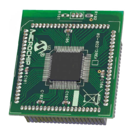
• XLP 16-Bit Development Board with a preprogrammed PIC24F16KA102 microcontroller installed • USB mini-B cable DEVELOPMENT BOARD FEATURES A layout of the XLP 16-Bit Development Board is shown in Figure 1-1. The board includes these specific features, as indicated in the diagram: 1. - Page 15 Introduction to the XLP 16-Bit Board FIGURE 1-1: XLP 16-BIT BOARD COMPONENT LAYOUT 2009-2015 Microchip Technology Inc. DS50001873C-page 15...
-
Page 16: Using The Development Board Out Of The Box
XLP 16-Bit Development Kit User’s Guide USING THE DEVELOPMENT BOARD OUT OF THE BOX Although intended as a development platform, the XLP 16-bit board may also be used directly from the box as a demonstration platform for the preprogrammed PIC24F16KA102 microcontroller. -
Page 17: Chapter 2. The Xlp Demonstration Application
Installing the Software and Driver Before connecting the board to the PC for the first time, install the USB Serial Converter driver. The instructions for this process are provided with the XLP 16-bit Development Kit source code distribution, which is available at: http://www.microchip.com/xlp16bitboard. -
Page 18: Demonstration Program Operation
At this point, the terminal is connected to the XLP board and communicating through the emulated serial port. It may be necessary to press S1 (Master Clear) to reset to the PIC24F microcontroller and obtain a display. - Page 19 The XLP Demonstration Application On power-up, the PIC24F16KA102 device will wake-up every 10 seconds from a Real-Time Clock Calendar (RTCC) interrupt, then re-enter Sleep mode. While awake, the microcontroller takes a temperature measurement using the MCP9700 tempera- ture sensor and writes the information to the serial EEPROM. Status information is displayed, including the wake-up source, Low-Power mode, selected sensor, data EEPROM information and current temperature.
- Page 20 XLP 16-Bit Development Kit User’s Guide FIGURE 2-2: DEMO APPLICATION SOFTWARE FLOW Reset Transmit Press Press Erase Stored Button Press? Datalog EEPROM Data Process Wake-up or Reset Source Button Press? S2 Hold S2 Press S3 Press S3 Hold Switch Force...
- Page 21 Sleep and Idle modes for the PIC24F microcontroller. In Deep Sleep, most micro- controller functions are disabled to minimize power consumption. The available wake-up sources supported by the XLP 16-Bit Development Kit are the RTCC interrupt, External Interrupt 0 (INT0) and MCLR Reset. When Idle mode is selected, all peripherals continue to operate;...
- Page 22 XLP 16-Bit Development Kit User’s Guide • DEFAULT_MODE sets the default Low-Power mode, selecting between Sleep, Deep Sleep and Idle modes. If held-button detection is enabled, the Low-Power mode can be changed at run time; otherwise, the selected mode is always used.
-
Page 23: Chapter 3. Xlp 16-Bit Development Board Hardware
This chapter provides a more detailed description of the hardware features of the XLP 16-Bit Development Kit. HARDWARE FEATURES The key features of the XLP 16-bit board are listed below. They are represented in the order given in Section 1.4 “Development Board Features”... - Page 24 3.2.3 Power Sources The XLP 16-bit board can use any one of six power options for full operation: 1. Bus power via the USB connector (J9). This provides a nominal 5V power source, regulated to approximately 3.3V for the microcontroller and board com- ponents, through a Schottky diode and Low Dropout (LDO) regulator circuit (D7, Q1).
- Page 25 3.2.3.4 ON-CHIP REGULATOR CONFIGURATIONS (PIC24F J-SERIES) The XLP 16-bit board supports multiple regulator configurations for PIC24F devices with an internal voltage regulator. A slider switch (S4) allows the user to configure the board for either J-series or K-series Flash devices. With switch, S4, in the “PIC24FJ”...
- Page 26 In many capacitive touch applications, an overlay is used to protect the PCB. Mounting holes are provided to secure overlay materials for evaluation. The low pin count devices, supported by the XLP 16-bit board, require that the touch pads be multiplexed with other board components. Specifically, CT2 is multiplexed with the temperature sensor circuitry, while CT3 is shared with the “Cap Sense”...
- Page 27 The XLP 16-bit board also implements a conventional junction diode connected to an analog input to demonstrate low-cost temperature sensing. The Charge Time Measurement Unit (CTMU) provides a specified current to the diode; an A/D conver- sion determines the voltage across the diode.
- Page 28 3.2.14 RS-232 Serial Port Options The XLP 16-bit board supports two types of RS-232 transceivers and associated sup- port circuitry through a standard DB9 connector. This port is configured as a DCE device and can be connected to a PC using a straight-through cable. Hardware flow control is not supported.
-
Page 29: Current Measurement
C bus in their application. CURRENT MEASUREMENT One of the great advantages of the XLP 16-bit board is its provisions for in-circuit current measurement. Using simple techniques and equipment, users can experiment directly with low-power hardware and software techniques, then directly measure their current consumption without introducing measurement induced artifacts. - Page 30 3.3.3 Ammeter Tool Header The XLP 16-bit board includes a special 7-pin header (J10) for current measurement. The PIC MCU PWR and IC PWR jumpers (JP9 and JP10) ensure continuity of power when connecting or disconnecting a current measurement device. Microchip provides an optional XLP Current Measurement Cable (part number AC002023) as a convenient way of connecting the header to an ammeter.
-
Page 31: Appendix A. Development Kit Schematics
XLP 16-BIT DEVELOPMENT KIT USER’S GUIDE Appendix A. Development Kit Schematics The following schematic diagrams are included in this appendix: • Figure A-1: Microcontroller Sockets/Headers and Associated Components • Figure A-2: USB/Serial Interface, EEPROM, Temperature Sensors and 28-Pin Interface •... - Page 32 XLP 16-Bit Development Kit User’s Guide FIGURE A-1: DEVELOPMENT BOARD SCHEMATIC, SHEET 1: MICROCONTROLLER SOCKETS/HEADERS AND ASSOCIATED COMPONENTS 2009-2015 Microchip Technology Inc. DS50001873C-page 32...
- Page 33 Development Kit Schematics FIGURE A-2: DEVELOPMENT BOARD SCHEMATIC, SHEET 2: USB/SERIAL INTERFACE, EEPROM, TEMPERATURE SENSORS AND 28-PIN INTERFACE 2009-2015 Microchip Technology Inc. DS50001873C-page 33...
- Page 34 XLP 16-Bit Development Kit User’s Guide FIGURE A-3: DEVELOPMENT BOARD SCHEMATIC, SHEET 3: POWER CIRCUIT AND SELECTOR JUMPERS 2009-2015 Microchip Technology Inc. DS50001873C-page 34...
- Page 35 Development Kit Schematics FIGURE A-4: DEVELOPMENT BOARD SCHEMATIC, SHEET 4: UNPOPULATED CIRCUITS (RS-232 AND I C™ HEADER) 2009-2015 Microchip Technology Inc. DS50001873C-page 35...
- Page 36 XLP 16-Bit Development Kit User’s Guide NOTES: 2009-2015 Microchip Technology Inc. DS50001873C-page 36...
-
Page 37: Index
XLP 16-BIT DEVELOPMENT KIT USER’S GUIDE Index Ammeter Tool Header..........30 PIC24F Current Measurement ........29 Feature Availability by Device Family ....23 Board Component Layout ........15 Oscillator Options..........23 Board Features ............14 Processor Support ..........23 PIC24F Device Sockets ........... 14 Potentiometer............. -
Page 38: Worldwide Sales And Service
Tel: 886-2-2508-8600 China - Xian Tel: 631-435-6000 Tel: 86-29-8833-7252 Fax: 886-2-2508-0102 San Jose, CA Fax: 86-29-8833-7256 Thailand - Bangkok Tel: 408-735-9110 Tel: 66-2-694-1351 Canada - Toronto Fax: 66-2-694-1350 Tel: 905-673-0699 Fax: 905-673-6509 01/27/15 2009-2015 Microchip Technology Inc. DS50001873C-page 38...
Need help?
Do you have a question about the XLP and is the answer not in the manual?
Questions and answers