Table of Contents
Advertisement
Quick Links
PD-9501-5GCO/DC PoE User Installation Guide
Introduction
Microchip's family of Power over Ethernet (PoE) Midspans PD-9501-5GCO/DC is a single-port high-power PoE
outdoor solution that offers a cost-effective IEEE
standard guaranteeing 60W of power and ensures safe and reliable operation in outdoor environments for standard
PoE data terminal. The PD-9501-5GCO/DC supports emerging wireless 5 Gbps devices such as wireless IEEE
802.11ac access points.
PoE Midspan powers devices that are PoE enabled or equipped to receive PoE. These devices are called PDs.
PoE Midspans offer the following key features:
•
Outdoor rated: IP66 and IP67
•
Extended temperature range –40 °C to 65°C
•
Supports 10/100/1000 Mbps and 2.5/5 Gbps data rates
•
Standards compliant: IEEE 802.3bt and IEEE802.3af/at
•
Plug and play installation (installer does not have to open unit)
•
Includes integrated surge protection
©
2021 Microchip Technology Inc.
and its subsidiaries
PD-9501-5GCO/DC
®
802.3bt compliant solution and pre-BT support for IEEE 802.3af/at
User Guide
DS00004336A-page 1
Advertisement
Table of Contents

Related Manuals for Microchip Technology PD-9501-5GCO/DC


Summary of Contents for Microchip Technology PD-9501-5GCO/DC
-
Page 1: Introduction
802.3bt compliant solution and pre-BT support for IEEE 802.3af/at standard guaranteeing 60W of power and ensures safe and reliable operation in outdoor environments for standard PoE data terminal. The PD-9501-5GCO/DC supports emerging wireless 5 Gbps devices such as wireless IEEE 802.11ac access points. -
Page 2: Table Of Contents
The Microchip Website..........................19 Product Change Notification Service......................19 Customer Support............................19 Microchip Devices Code Protection Feature....................19 Legal Notice..............................19 Trademarks..............................20 Quality Management System........................21 Worldwide Sales and Service........................22 User Guide DS00004336A-page 2 © 2021 Microchip Technology Inc. and its subsidiaries... -
Page 3: Standards And Safety Guidelines
GS marking on this product indicates that the product complies with the German Product Safety Act. Surge/Lightening Protection Microchip’s PD-9501-5GCO/DC is designed according to the following EMC requirements. • ITU-T K.21 (6 kV enhanced surge) — Port and DC Main •... -
Page 4: Safety Information
Data and Data and Power ports of the Midspan are shielded RJ45 data sockets. They cannot be used as Plain Old Telephone Service (POTS) sockets. Only connect RJ45 data connectors to these sockets. • When disposing this product, follow all local laws and regulations. User Guide DS00004336A-page 4 © 2021 Microchip Technology Inc. and its subsidiaries... -
Page 5: Information En Matière De Sécurité
être utilisées comme prises de service téléphonique traditionnel. Connecter seulement des connecteurs de données RJ45 à ces prises. Le câblage Ethernet connexe doit être limité à l'intérieur de l'immeuble. • Pour disposer/jeter ce produit, suivre les lois et règlements locaux. User Guide DS00004336A-page 5 © 2021 Microchip Technology Inc. and its subsidiaries... -
Page 6: Poe Midspan Installation (Outdoor Model)
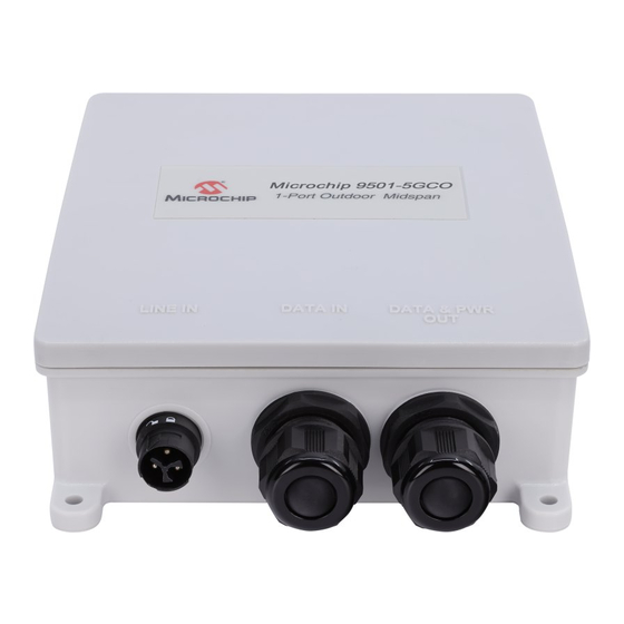
Ensure the DC power is within the allowed range. Earth ground screw must be connected to earth ground in all types of installations. Installation Overview Figure 3-1. Product Overview User Guide DS00004336A-page 6 © 2021 Microchip Technology Inc. and its subsidiaries... - Page 7 Installation Options There are two options available for the installation of PD-9501-5GCO/DC: Wall installation – PoE Midspan unit can be mounted on a wall/bench (all kind of flat surfaces such as wood, brick, concrete etc.) using the mounting holes.
- Page 8 Connect the chassis bolt to the earth ground point on the rear of the midspan. Connect the other end of the ground wire to earth ground at your installation point. Tighten the screw to 1.7 Nm. User Guide DS00004336A-page 8 © 2021 Microchip Technology Inc. and its subsidiaries...
- Page 9 Before installing the midspan, ensure that all the following parts listed in the parts list are included. If any items are missing, notify your Sales or Customer Service Representative from Microchip. Install the midspan onto the mounting bracket of the pole mount adapter, using four pan head screws. User Guide DS00004336A-page 9 © 2021 Microchip Technology Inc. and its subsidiaries...
- Page 10 Pole of large diameter: The following parts list identifies the components required to install the metal bracket on a pole with a diameter of 76 mm to 203 mm (3 in. to 8 in.). User Guide DS00004336A-page 10 © 2021 Microchip Technology Inc. and its subsidiaries...
- Page 11 For poles of both small and large diameter, connect the chassis bolt to the earth ground point on the mount kit. Warning: Mounting bracket must be connected to earth ground. User Guide DS00004336A-page 11 © 2021 Microchip Technology Inc. and its subsidiaries...
- Page 12 The following figure shows how to connect the DC cable to the midspan unit: Figure 3-2. Connecting the DC Cable to the Unit 8mm (5 /16 in) 0.5 Nm 25mm (1 in) “-“ “+“ 1.5 Nm User Guide DS00004336A-page 12 © 2021 Microchip Technology Inc. and its subsidiaries...
- Page 13 Repeat step to step to connect the RJ45 cable to the Data and PWR Out port. Note: Use cable up to 5 Gig Cat 5e and above outdoor grade. User Guide DS00004336A-page 13 © 2021 Microchip Technology Inc. and its subsidiaries...
- Page 14 LINE IN Power Input, 12 V –24 V DATA IN Data In to the Ethernet (network) switch DATA & PWR OUT Data and Power Out to the Ethernet terminal User Guide DS00004336A-page 14 © 2021 Microchip Technology Inc. and its subsidiaries...
-
Page 15: Troubleshooting
UTP/FTP Category 5/5e/6 straight (non- crossover) cabling, with all four pairs. Verify that the Ethernet cable length is less than 100 meters from Ethernet source to the remote terminal. User Guide DS00004336A-page 15 © 2021 Microchip Technology Inc. and its subsidiaries... -
Page 16: Specifications
RJ45 female socket, with DC voltage on wire pairs: 7-8, 4-5 and 2.5Gig/5Gig/10Gig Base-T, plus 54 V and 1-2, 3-6 DC Power In 2 Pins DC power in – Positive and Negative User Guide DS00004336A-page 16 © 2021 Microchip Technology Inc. and its subsidiaries... -
Page 17: Contacting Technical Support
If you encounter any problems while installing or using this product, consult the Microchip technical support team through the website or contact on the following number: USA/Canada Telephone: +1 877 480 2323 Internet: www.microchip.com/support User Guide DS00004336A-page 17 © 2021 Microchip Technology Inc. and its subsidiaries... -
Page 18: Revision History
PD-9501-5GCO/DC Revision History Revision History Revision Date Description 12/2021 Initial Revision. User Guide DS00004336A-page 18 © 2021 Microchip Technology Inc. and its subsidiaries... -
Page 19: The Microchip Website
It is your responsibility to ensure that your application meets with your specifications. Contact your local Microchip sales office for additional support or, obtain additional support at www.microchip.com/en-us/support/ design-help/client-support-services. User Guide DS00004336A-page 19 © 2021 Microchip Technology Inc. and its subsidiaries... -
Page 20: Trademarks
The Adaptec logo, Frequency on Demand, Silicon Storage Technology, Symmcom, and Trusted Time are registered trademarks of Microchip Technology Inc. in other countries. GestIC is a registered trademark of Microchip Technology Germany II GmbH & Co. KG, a subsidiary of Microchip Technology Inc., in other countries.
Need help?
Do you have a question about the PD-9501-5GCO/DC and is the answer not in the manual?
Questions and answers