Bürkert 8611 Operating Instructions Manual
Econtrol
Hide thumbs
Also See for 8611:
- Operating instructions manual (80 pages) ,
- Quick start manual (56 pages) ,
- Quick start manual (142 pages)

Related Manuals for Bürkert 8611


Summary of Contents for Bürkert 8611
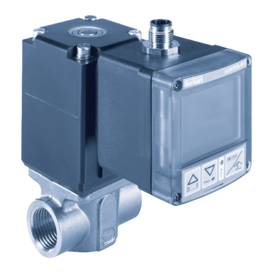
- Page 1 Type 8611 eCONTROL Process controller and Ratio controller Operating Instructions (Valid from software version B01)
- Page 2 We reserve the right to make technical changes without notice. Technische Änderungen vorbehalten. Sous réserve de modification technique. © 2009 - 2012 Bürkert SAS Operating Instructions 1209/4_EUen_00805625 / Original: DE...
-
Page 3: Table Of Contents
Type 8611 eCONTROL 8611: Process Controller and Ratio Controller ontents Operating instructiOns ................................6 1.1. symbols....................................6 authOrized use .....................................7 restrictions .....................................7 2.1. 2.2. predictable Misuse ................................7 Basic safety instructiOns ..............................8 general infOrMatiOn ................................9 contact addresses ................................9 4.1. 4.2. Warranty ....................................9 information on the internet ............................9 4.3. - Page 4 Type 8611 electrical installatiOn ..............................20 8.1. electrical installation for fitting assembly, wall assembly, valve assembly or rail assembly models ....................................20 electrical installation of the control cabinet model ..................24 8.2. OperatiOn and functiOn ..............................27 9.1. control and display elements ............................27 Operating levels and operating states .........................28 9.2. function of the keys ...............................29 9.3. Operating structure ................................30 10. 10.1. Operating structure of the process operating level in Manual operating state ......30 10.2. Operating structure of the configuration level ....................31 functiOns Of the prOcess Operating level ....................37 11. 11.1. Operating state autOMatic .............................37 11.2. Operating state Manual .............................38 11.3. specific menu options of process and ratio control .
- Page 5 Type 8611 (4 - 20 ma or 0 - 10 v) ......................64 12.7. aOut - s caling of analog output (4 - 20 ma or 0 - 10 v) ....................65 12.8. c ali - c alibration of the analog inputs and outputs ..................67 12.9. calibration of the assembly models: Wall, rail, valve or fitting assembly ..........................68 12.10. calibration of the control cabinet model ......................69 12.11. Kfac - e ntry of K-factor for flow-rate measurement ...................70 12.12. filt - f iltering of the process actual value input ...................72 12.13. para - adjusting the controller parameters .....................73 12.14. B_in - c onfiguration of binary input ........................81 12.15. B_O1 - c onfiguration of the binary output .
-
Page 6: Operating Instructions
Type 8611 OperatingInstructions OperaTing insTrucTiOns The operating instructions describe the entire life cycle of the device. Keep these instructions in a location which is easily accessible to every user, and make these instructions available to every new owner of the device. -
Page 7: Authorized Use
If exporting the system/device, observe any existing restrictions. 2.2. predictable Misuse • The Type 8611 is not to be used in areas where there is a risk of explosion. • Do not physically stress the housing (e.g. by placing objects on it or standing on it). english... -
Page 8: Basic Safety Instructions
• Also, ensure that you do not touch electronic components when the power supply voltage is present! The process controller Type 8611 was developed with due consideration given to the accepted safety rules and is state-of-the-art. Nevertheless, dangerous situations may occur. -
Page 9: General Information
The warranty is only valid if the device is used as intended in accordance with the specified application conditions. 4.3. information on the internet The operating instructions and data sheets for Type 8611 can be found on the Internet at: www.burkert.com english... -
Page 10: System Description
5.1. general description The process controller Type 8611 is designed for integration in a closed control circuit and can be used for numerous control tasks in fluid technology. The figure below illustrates the integration of the controller in a closed control circuit. -
Page 11: Functions
In the following description of the menu options and their operating structures, the entire software of the eCONTROL Type 8611 is explained. This complete software scope is only available for the control cabinet model of the eCONTROL Type 8611. -
Page 12: Technical Data
Type 8611 TechnicalData Technical daTa 6.1. Operating conditions Permitted ambient temperature: (operation and storage) 0 ... +70 °C ≤ 80 %, non condensing Max. permitted humidity: Protection class: IP65 to EN 60529 6.2. conformity with the following standards CE mark conforms to... -
Page 13: Rating Plate Description
- Rail (rail assembly) - Valve (assembly directly on valve) - Fitting (assembly directly on flow-rate fitting) Power supply voltage 8611 Wall 24VDC Sensor input signal (Norm, Pt 100 or Freq (NPN)) IN:Norm OUT:Norm Analog output (Norm or None) SET: Norm... -
Page 14: Electrical Data
Type 8611 TechnicalData 6.5. electrical data Operating voltage: 24 V DC ±10 %, filtered and controlled Power consumption without load: approx. 2 W with load: maximum 48 W 100 % ED: 36 W Controller sampling rate: 300 Hz 6.5.1. inputs set-point value 70 Ω... - Page 15 Type 8611 TechnicalData 6.5.2. Outputs Continuous signal Standard signal 4 - 20 mA 680 Ω Max. loop resistance: Precision: 0,5 % Standard signal 0 - 10 V Maximum current: 20 mA Precision: 0,5 % Discontinuous signal 2 transistor outputs for PWM or PTM control Control frequency: 1.2 kHz ...
-
Page 16: Assembly
Type 8611 Assembly asseMBly 7.1. assembly models attachment to a Bürkert flow-rate fitting attachment to a proportional valve Bürkert flow-rate fitting Type SO30 installation in a control cabinet Wall assembly or rail assembly The description of the installation in a control cabinet and the device dimensions can be found in the following chapter “7.3. Assembly of the control... -
Page 17: Attachment To A Proportional Valve
Type 8611 Assembly 7.2. attachment to a proportional valve Attach the process controller Type 8611 to a proportional valve as described below. → Loosen the 4 screws at the front of the process controller. NOTe! Be careful when opening the process controller so as not to damage the internal cabling. • Remove the cover carefully from the housing without jerks. -
Page 18: Assembly Of The Control Cabinet Model
Type 8611 Assembly 7.3. assembly of the control cabinet model 7.3.1. device dimensions and control panel cut-out 54.2 44.5 Control panel cut-out for the installation Figure 6: Device dimensions and control panel cut-out english... - Page 19 Type 8611 Assembly 7.3.2. installation in a control cabinet • Prepare control panel cut-out with the dimensions 45mm x 45mm (corner radius 3mm). • Place the supplied seal on the housing. • Insert the controller from the front into the control panel cut-out.
-
Page 20: Electrical Installation
Type 8611 ElectricalInstallation elecTrical insTallaTiOn 8.1. electrical installation for fitting assembly, wall assembly, valve assembly or rail assembly models 8.1.1. connection versions connector connector view configuration Circular plug-in Power supply voltage, connector set-point input 4 - 20 mA / 0 - 10 V,... - Page 21 Type 8611 ElectricalInstallation 8.1.2. pin assignment circular plug-in connector M12, 8-pole A straight connector (female) is recommended for the connecting cable as the orientation of the con- nector may vary. connector color configuration diagram white 24 V DC power supply 2 (DIN2) brown Binary input (B_IN) green GND –...
- Page 22 NO valve 4 (BO4) black (+) Deaeration (valve 2) 1 (BO3) brown + 24 V DC supply Supply of 8611 4 - 20 mA white GND (4 - 20 mA or 0 - 10 V) or 0 - 10 V...
- Page 23 Type 8611 ElectricalInstallation Output color configuration external circuit signal: 1 (BO3) brown (+) Valve 1 NC / NO valve 3-point white (–) Valve 1 (MODE = blue (–) Valve 2 3P – T) NC / NO valve 4 (BO4) black (+) Valve 2...
-
Page 24: Electrical Installation Of The Control Cabinet Model
WaRNiNg! risk of injury from incorrect installation! Incorrect installation can damage or destroy the Type 8611 eCONTROL. • The electrical installation may be performed by authorized electricians only! 1 2 3 4 5 6 7 8 Terminal block 1... - Page 25 Type 8611 ElectricalInstallation terminal configuration external circuit MODE = 2P – T MODE = PCV (+) Aeration valve (PCV) or or 3P – T (BO3) valve 1 (2P – T or 3P – T) (–) Aeration valve (PCV) or NC / NO valve 1 (2P –...
- Page 26 GND – Sensor, actuating element 24 V DC sensor supply or 24 V DC - Out (max. 1 A) actuating element Frequency input 2 Jumper 2 Supply of 8611 (NPN or PNP) Supply of 24 V DC 12 or 24 Type 8611...
-
Page 27: Operation And Function
Type 8611 OperationandFunction OperaTiOn and funcTiOn 9.1. control and display elements The control and display element of the eCONTROL Type 8611 is equipped with 3 buttons and an LCD-Matrix display. 9.1.1. display elements 4-character display 7-character matrix for numerical values... -
Page 28: Operating Levels And Operating States
Operating levels and operating states 2 operating levels and 2 operating states AUTOMATIC and MANUAL are available for the operation and setting of the eCONTROL Type 8611. level 1: p rocess operating level At level 1, the user can switch between 2 operating states AUTOMATIC and MANUAL. -
Page 29: Function Of The Keys
Type 8611 OperationandFunction 9.3. function of the keys The device is operated using two arrow keys and one ENTER key. The function of these in respect of the operating level and the operating state is shown in Table 12 below. -
Page 30: Operating Structure
Type 8611 OperatingStructure OperaTing sTrucTure 10.1. Operating structure of the process operating level in Manual operating state The SET menu option is Enter set-point value SET *** only displayed for process RFAC **** Enter ratio factor control. Consequently for all control... -
Page 31: Operating Structure Of The Configuration Level
Type 8611 OperatingStructure 10.2. Operating structure of the configuration level Configuration level Enter access code if the code protection has been activated in the CODE menu. CODE MODE CODE FREQ RATI „0001“ NORM Select control frequency FREQ * (PWM) PT *... - Page 32 Type 8611 OperatingStructure UNIT * The display depends on the control variable set in the MODE menu (see chapter 12.3) 0.01 µS/c mS/c Ωxc Enter The SETP menu option is 4 – 20 SETP ** scaling only displayed for RFAC *** 0 –...
- Page 33 Type 8611 OperatingStructure select K-factor for ratio control KFAC * Q1 ** Q1 and Q2 are only displayed if frequency input (FREQ) was selected for both flow-rate sensors in ratio control. Q2 ** Enter value FREE 0.01 The display 0.01, 0.1, 1 is used for setting the decimal place.
- Page 34 Type 8611 OperatingStructure Enter filter factor ( 2 - 20) FILT PARA KP2 * TREG * TN * The display depends on the control variable set in the MODE DEAD menu (see chapter 12.3) KP_T * TN_T * DE_T *...
- Page 35 Type 8611 OperatingStructure B _O1 selecting binary output as pulse output Enter number PULS of pulses IGAL UGAL 0.01 selecting binary output as limit switch Enter LIMT hyteresis values Enter process FLOW limit value PRES The display depends on the control variable set TEMP in the MODE menu: LEVL (see chapter 12.3)
- Page 36 Type 8611 OperatingStructure VALV MODE = SCV, 4 - 20, 0 - 10: Continuous control The display depends on the control variable set in the MODE menu (see chapter 12.3) MODE = PCV, 2P - T, 3P - T: Quasi-continuous control...
-
Page 37: Functions Of The Process Operating Level
Type 8611 FunctionsoftheProcessOperatingLevel funcTiOns Of The prOcess OperaTing leVel 11.1. Operating state auTOMaTic After switching on the operating voltage, the controller is at the process operating level and in the AUTOMATIC operating state. The normal control mode is executed and monitored. -
Page 38: Operating State Manual
Type 8611 FunctionsoftheProcessOperatingLevel 11.2. Operating state Manual Briefly press (< 1 s) the ENTER key to go to the MANUAL operating state. The operating state is indicated on the display by a hand symbol. 11.3. specific menu options of process and ratio control The display of some menu options differs for the process and the ratio control. -
Page 39: Set - Set-Point Value Default For Process Control
Type 8611 FunctionsoftheProcessOperatingLevel 11.5. SET - set-point value default for process control In the case of process control, the set-point value default can be entered in the MANUAL operating state using the SET menu. Process control is active if all control variables have been set in the MODE menu except for RATI. -
Page 40: Test - Display Of The Analog Inputs And Outputs And The Digital Inputs
Type 8611 FunctionsoftheProcessOperatingLevel 11.7. TEST – display of the analog inputs and outputs and the digital inputs The analog inputs and outputs and the digital inputs are displayed while the controller is operating. No changes can be made. Analog input 1: 4 - 20 mA or 0 - 10 V... -
Page 41: Para - Display And Optimization Of The Controller Parameters
Type 8611 FunctionsoftheProcessOperatingLevel 11.8. PARA – display and optimization of the controller parameters In this menu of the process operating level, the controller parameters of the running process can be optimized. The new controller parameters are taken over immediately after pressing the ENTER key. -
Page 42: Valv - Manual Opening And Closing Of The Connected Actuating Elements
Type 8611 FunctionsoftheProcessOperatingLevel 11.9. VALV – Manual opening and closing of the connected actuating elements If the VALV menu option is selected, the controller is stopped and the actuating element remains in the last position. The manipulated variable can now by increased or lowered relatively to the last position by pressing the key. - Page 43 Type 8611 FunctionsoftheProcessOperatingLevel MODE = PCV, 2P - T, 3P - T (Reset time T deactivated, T = 9999) Display process value 1 5 0 VALV In the case of cascaded control, the process value and the flow-rate are displayed alternately...
-
Page 44: Functions Of The Configuration Level
In the following description of the menu options and their operating structures, the entire software of the eCONTROL Type 8611 is explained. This complete software scope is only available for the control cabinet model of the eCONTROL Type 8611. -
Page 45: Menu Options Of The Configuration Level
Type 8611 FunctionsoftheConfigurationLevel 12.2. Menu options of the configuration level selection of control variable, actuating element and process value input. MODE See Chapter 12.3 selection of measuring units and decimal places. UNIT See chapter 12.4 selection and scaling of set-point value default. SETP See chapter 12.5 entry of ratio factor for ratio control (MODE = RATI). RFAC See chapter 12.5 scaling of sensor input signal ( 4 - 20 ma or 0 - 10 v). S_IN See chapter 12.6 scaling of analog output (4 - 20 ma or 0 - 10 v). AOUT See chapter 12.7 calibration of the analog inputs and outputs. -
Page 46: Mode - Selection Of Control Variable, Actuating Element And Process Value Input
Type 8611 FunctionsoftheConfigurationLevel 12.3. MODE - selection of control variable, actuating element and process value input The most important basic settings of the controller are made in this menu option. The setting is done in 3 successive steps. • Selection of control variable (e.g. flow-rate control, pressure control, etc.) •... - Page 47 Type 8611 FunctionsoftheConfigurationLevel MODE selection of control variable selection of actuating element Continuous control using proportional Select valve and selection of PWM frequency PWM frequency (see chapter 12.3.2) Quasi-continuous control Select using process valve control times (see chapter 12.3.3) Quasi-continuous 3-state control with Select 3P – T...
- Page 48 12.3.1. RATI - selection of external sensors for ratio control A ratio control can easily be implemented by combining the compact controller Type 8611 with flow-rate fitting S030 and a second flow-rate sensor. In a ratio control, the controlled flow-rate Q...
- Page 49 Type 8611 FunctionsoftheConfigurationLevel Settings in the menu: 0 0 0 1 MODE CODE select frequency input for sensor input Q selection of control variable RATI FREQ select standard signal for sensor input Q NORM FREQ: The sensor-specific K-factor is entered in the Continue with KFAC menu. selection of actuating element (see chapter 12.3.2 to NORM: The scaling of the standard signal is selected in chapter 12.3.6)
- Page 50 SCV - continuous control using proportional valve The settings of the eCONTROL Type 8611 are made in this menu if a proportional valve is used. It is very important and crucial for a good control that the control frequency (PWM frequency) is set according to the selected valve type.
- Page 51 All Bürkert proportional valves with the corresponding PWM frequency are saved in the menu of the eCONTROL Type 8611 and can be selected there. The table with the PWM frequencies is available on the internet at www.burkert.com. By setting the valve type, the two limit frequencies of the PWM control (f and f ) are set.
- Page 52 Type 8611 FunctionsoftheConfigurationLevel Setting the PWM frequency in the menu: 0 0 0 1 Selection of MODE control variable CODE setting the pWM frequency 0 0 0 0 ..PWM frequency 0 7 2 5 2821 Bürkert Type Manual entry of...
- Page 53 Type 8611 FunctionsoftheConfigurationLevel parameterization: Single-acting, pneumatically operated control valves with "normal closed" function can be operated. Two control valves are required for the pneumatic control of the process valve (see Figure 34). y 2 (ms) Controller setting: y 1 (ms)
- Page 54 Type 8611 FunctionsoftheConfigurationLevel Bleed valve (NO operating principle = Normally open / opened with no current) Aeration valve (NC operating principle = Normally closed / closed with no current) Figure 35: Control block 8810 for control of the process valve If control valves other than those of Type 8810 are used, the opening time specified in the data sheet for "TMN1"...
- Page 55 Type 8611 FunctionsoftheConfigurationLevel Setting the minimum control time in the menu: 0 0 0 1 Selection of MODE control variable CODE enter minimum control time for control valves 0 0 0 5 0 0 0 5 TMN1 TMN2 Continue with selection of process value input see Figure 27 Figure 36: PCV;...
- Page 56 Type 8611 FunctionsoftheConfigurationLevel 12.3.5. 2P – T - Quasi-continuous 2-state control with open/ closed valves This function can be used to implement quasi-continuous controls using open/closed valves. Here, unlike in purely open/closed controls that only provide for the states open or closed, the control time for the opening or closing is varied proportionally to the set-point/actual value deviation.
- Page 57 Type 8611 FunctionsoftheConfigurationLevel 12.3.6. 3P – T - Quasi-continuous 3-state control with open/closed valves or motor valve This function can be used to implement quasi-continuous controls using open/closed valves or motor valves. Here, unlike in purely open/closed controls that only provide for the states open or closed, the control time for the opening or closing is varied proportionally to the set-point/actual value deviation.
- Page 58 Type 8611 FunctionsoftheConfigurationLevel Setting the quasi-continuous 3-state control in the menu: selection of three-state control 0 0 0 1 Selection of MODE 3P – T control variable CODE selection of operating principle and enter minimum control time 0 0 0 1 0 0 0 1 VLV1 TMN1 VLV2 TMN2 VLV1...
-
Page 59: Unit - Selection Of Measuring Units And Decimal Places
Type 8611 FunctionsoftheConfigurationLevel 12.4. UNIT - selection of measuring units and decimal places In this menu option, the measuring units and the number of decimal places (see Table 20) are selected for the displayed values. What measuring unit is selected in the UNIT menu depends on the control variable set in the MODE menu. - Page 60 Type 8611 FunctionsoftheConfigurationLevel selected control variable UNIT MODE = T Degrees/Celsius °C Degrees/Fahrenheit °F Display without measuring unit DP_T 0 . 1 DP_T 0 . 0 1 DP_T selected control variable MODE = T + F, T - F Degrees/Celsius °C Degrees/Fahrenheit °F Display without measuring unit DP_T 0 .
- Page 61 Type 8611 FunctionsoftheConfigurationLevel selected control variable UNIT MODE = L Meters Centimeters Millimeters Inch Feet DP_L 0 . 1 DP_L 0 . 0 1 DP_L selected control variable MODE = X pH value Display without measuring unit Conductivity (Ohm · cm) Ωxc Conductivity (Siemens/cm)
-
Page 62: Setp / Rfac - S Election And Scaling Of Set-Point Value Default / Entry Of Ratio Factor
Type 8611 FunctionsoftheConfigurationLevel 12.5. SETP / RFAC - selection and scaling of set-point value default / entry of ratio factor When selecting the set-point value default, the display in the menu makes a distinction between the set-point value for the process control and the set-point value for the ratio control. - Page 63 Type 8611 FunctionsoftheConfigurationLevel display SETP description Internal set-point value default. Is entered in the operating state MANUAL in the SET menu using the keyboard. See chapter “11.5. SET - Set-point value default for process control” External process set-point value default using standard signal (4 - 20 mA or 0 - 10 V).
-
Page 64: S_In - Scaling Of Sensor Input Signal
Type 8611 FunctionsoftheConfigurationLevel 12.6. S_IN - scaling of sensor input signal (4 - 20 ma or 0 - 10 V) The S_IN menu is only displayed if an analog sensor input was selected in the MODE menu. Setting in the menu:... -
Page 65: Aout - Scaling Of Analog Output
Type 8611 FunctionsoftheConfigurationLevel 12.7. AOUT - scaling of analog output (4 - 20 ma or 0 - 10 V) The analog output is selected and scaled in this menu. The AOUT menu is not displayed if, in the MODE menu, 4 - 20 or 0 - 10 was selected as actuating element. - Page 66 Type 8611 FunctionsoftheConfigurationLevel display description Output of actuating element position (only for actuating element type MODE = SCV) Value range: 000.0 - 100.0 000.0 = valve closed 100.0 = valve open Output of flow-rate Q1 for ratio control (control variable MODE = RATI)
-
Page 67: Cali - Calibration Of The Analog Inputs And Outputs
The calibration must be done by trained staff only All analog inputs and outputs were calibrated at the factory prior to delivery of the controller Type 8611. However, it is possible to recalibrate the analog inputs and outputs for services purposes or for checking the calibration. -
Page 68: Calibration Of The Assembly Models
Type 8611 FunctionsoftheConfigurationLevel 12.9. calibration of the assembly models: Wall, rail, valve or fitting assembly Menu description circular plug-in external circuit connector Use standard signal transmitter to apply a defined voltage (max. 10 V) or defined current SETA, (max. 20 mA), as shown in the columns on the... -
Page 69: Calibration Of The Control Cabinet Model
Type 8611 FunctionsoftheConfigurationLevel 12.10. calibration of the control cabinet model Menu description terminals external circuit Use standard signal transmitter to apply a defined voltage (max. 10 V) or defined current (max. 20 mA), as shown in SETA, 14 (+) the columns on the right. -
Page 70: Kfac - Entry Of K-Factor For Flow-Rate Measurement
This is the case if a sensor with frequency input was selected. (MODE, selection of process value input, FREQ. See chapter 12.3). In the controller Type 8611, the respective K-factor is already pre-set for the sensors from Bürkert. Once the type and the flow-rate variable have been selected, the corresponding K-factor is displayed and confirmed with the ENTER key. - Page 71 Type 8611 FunctionsoftheConfigurationLevel Q1 and Q2 are only displayed if frequency input Q1 * (FREQ) was selected for both flow-rate sensors in Q2 * ratio control. 0 0 5 0 KFAC FREE DP_K KFAC 0 . 1 DP_K 0 . 0 1 The display 0.01, 0.1, 1 is used for setting the...
-
Page 72: Filt - Filtering Of The Process Actual Value Input
The following table contains a list of the frequency range (f ) and the period (T ) for the Bürkert flow-rate sensors that are stored in the eCONTROL Type 8611. Sampling frequencies under f are automatically detected by the eCONTROL Type 8611 as zero flow-rate. -
Page 73: Para - Adjusting The Controller Parameters
Type 8611 FunctionsoftheConfigurationLevel 12.13. PARA - adjusting the controller parameters In this menu, the following parameters can be set for the eCONTROL Type 8611: • Proportional coefficient (proportional gain for opening and closing the actuating element) KP , KP The influence that the proportional coefficient has with regard to the selected actuating element and how the proportional gain is calculated are described in the following chapter “12.3.1. - Page 74 Type 8611 FunctionsoftheConfigurationLevel Setting the controller parameters in the menu: set value PARA accept value KP1, proportional coefficient 1 0 1 . 5 0 0 1 . 5 0 Changing the decimal place (see Table 28) 0 1 . 5 0 0 1 . 5 0...
- Page 75 Type 8611 FunctionsoftheConfigurationLevel 12.13.1. KP1, KP2 - setting the proportional coefficient (proportional gain) Depending on the actuating element selected in the MODE menu (see chapter 12.3), the influence of the propor- tional coefficient varies. It serves as proportional gain [K ] either for opening or for closing the actuating element.
- Page 76 Type 8611 FunctionsoftheConfigurationLevel If the selected unit is changed in the UNIT menu, the proportional gain [K ] must be adapted accordingly. setting aid: An unsatisfactory dynamic of the control is improved by increasing the aproportional gain [K ]. The fol-...
- Page 77 Type 8611 FunctionsoftheConfigurationLevel Overview of the valve opening times of the Bürkert process valves depending on the actuator size and pilot pressure: actuator size [dn] pilot pressure Opening time for valve [s] closing time for valve [s] Table 28: Valve opening times for Bürkert process valves 0 – 10 - flow-rate control with motor valve and 0 - 10 V control (For schematic representation see “Figure 37: Example of a flow-rate control with 0 - 10 V control”)
- Page 78 Type 8611 FunctionsoftheConfigurationLevel setting aid: An unsatisfactory dynamic of the control is improved by increasing the proportional gain [K ]. The fol- lowing must be observed: In the event of impermissibly high overshoots after set-point value jumps or in the event of an unstable control, the proportional gain [K ] should be reduced.
- Page 79 Type 8611 FunctionsoftheConfigurationLevel 12.13.6. KP T – proportional gain of the cascaded temperature control This parameter is only available if the MODE = T + F process variable is selected and describes the proportional gain of the superimposed temperature controller. In the cascaded temperature control, the flow-rate control serves as subsidiary control circuit.
- Page 80 Type 8611 FunctionsoftheConfigurationLevel display description Not inverted or direct control (the process value increases with the opening of the valve) Inverted control (the process value decreases with the opening of the valve) Figure 57: Display INV 12.13.9. ZERO – zero point shut-off The zero point shut-off can be activated or deactivated.
-
Page 81: B_In - Configuration Of Binary Input
Type 8611 FunctionsoftheConfigurationLevel 12.14. B_IN - configuration of binary input The binary input allows for starting various controller functions. The feedback from a limit switch (for filling level, pressure, etc.), the feedback from a PLC, etc. may be binary input signals. -
Page 82: B_O1 - Configuration Of The Binary Output
Type 8611 FunctionsoftheConfigurationLevel display description SAFP Setting of a safety position that is approached when binary input is active. Depending on the actuating element, the following options can be selected: PRZV: Control ratio in [%] for proportional valves Control in [mA] for drives with current input as manipulated variable... - Page 83 Type 8611 FunctionsoftheConfigurationLevel 12.15.1. PULS - configuration of the binary output as pulse output In this menu, it can be defined when, referred to a specific flow-rate volume, a pulse signal is to be emitted. The measuring units and the volume per pulse can be selected as followed:...
- Page 84 Type 8611 FunctionsoftheConfigurationLevel 12.15.2. LIMT - configuration of the binary output as limit switch This menu can be used to set alarms or switching contacts if specific limit values are exceeded or not reached. Setting in the menu: B_O1 For description of the configuration PULS see „12.15.1.
- Page 85 Type 8611 FunctionsoftheConfigurationLevel display description LIMT Selection for the binary output with the function as limit switch. Limit states are monitored relatively to the set-point value (SETP) using a super- imposed switching hysteresis between the limit values (SETP+HYLO) and SETP- HYLO).
- Page 86 Type 8611 FunctionsoftheConfigurationLevel Schematic representation of a limit value monitoring referred to fixed process value limits: Process actual value Process value PVHI PVLO time Active HIGH 24 V (NC valve) DLY = 0 s Active LOW 24 V (NO valve)
- Page 87 Type 8611 FunctionsoftheConfigurationLevel 12.15.3. 2_P - configuration of the binary output as 2-state controller In the discontinuous 2-state control, an open/closed valve is opened or closed depending on two limit values, for example. Setting in the menu: B_O1 For selection for binary output as pulse output PULS see „12.15.1.
- Page 88 Type 8611 FunctionsoftheConfigurationLevel display description Selection for the binary output with the function as 2-state controller. The 2-state control is implemented relatively to the set-point value depending on the deviation between set-point value and actual process value. If the set-point value is changed, the control limits are adapted automatically.
- Page 89 Type 8611 FunctionsoftheConfigurationLevel Schematic representation of a 2-state control relatively to the set-point value: Process actual value Process value Set-point value SETP + HYHI HYHI SETP HYLO SETP - HYLO time inverted control (cooling) Active HIGH 24 V (NC valve) Active LOW...
-
Page 90: B_O2 - Second Binary Output
The description for binary output B_O2 is identical to that of binary output B_O1 (see chapter 12.15). As all models of the eCONTROL Type 8611 controller are equipped with the same software, the B_O2 menu option also exists in the assembly models for wall, rail, valve and fitting assembly, even though binary output B_O2 is not available. -
Page 91: Valv - Test Function And Setting Of The Control Range
Type 8611 FunctionsoftheConfigurationLevel 12.17. VALV - Test function and setting of the control range In this menu option, the actuating element can be operated manually, for instance in order to • test how the process variable responds to the change in manipulated variable or •... - Page 92 Type 8611 FunctionsoftheConfigurationLevel 12.17.2. control with p-action structure deactivated, T = 9999), MODE = PCV, 2P -T, 3P - T Setting in the menu: 1. Press the ENTER key to display the current process value. In the case of cascaded control, the process value and the flow-rate value are displayed alternately Press the up arrow key to open the actuating element, and the down arrow key to close the actuating element.
-
Page 93: Code - Code Protection
Type 8611 FunctionsoftheConfigurationLevel 12.18. CODE - code protection Access to the configuration level can be protected by a code. Any unauthorized persons are thus denied access and cannot change the parameters. If the code protection is activated, there is a prompt to input the code prior to each blocked operator action. -
Page 94: Dspl - Setting The Display
Type 8611 FunctionsoftheConfigurationLevel 12.19. DSPL - setting the display In this menu, the following settings for the display can be made: • Activation of the background lighting • Define what value or what manipulated variable should be displayed after switching on the voltage. -
Page 95: Fact - Reset To Factory Settings
Type 8611 FunctionsoftheConfigurationLevel 12.20. FACT - reset to factory settings In this menu, the controller Type 8611 can be reset to the factory settings it was delivered with. Setting in the menu: Enter access code 0003 Return without resetting of the settings... -
Page 96: End - Leaving The Configuration Level
Type 8611 FunctionsoftheConfigurationLevel 12.22. END - leaving the configuration level Press the ENTER key in the END menu option to leave the configuration level. After that, the controller is once again at the process operating level and in the AUTOMATIC operating state (see chapter “9.2.1. Switching between the operating levels and operating states”). -
Page 97: Overview Setting Parameters
Type 8611 OverviewSettingparameters OVerVieW seTTing paraMeTers continuous control Quasi-continuous control discontinuous control actuating propor- linear actuating process Open/ Open/ Open/ Open/ element tional element valve closed closed closed closed valve valve rotary valve valve actuator Program 0-10 4-20 2P – T 3P – T 2P –... -
Page 98: Maintenance, Troubleshooting
Type 8611 Maintenance,Troubleshooting MainTenance, TrOuBleshOOTing The process controller Type 8611 is maintenance-free when operated according to the instructions in this manual. 14.1. Malfunctions The table below contains the possible error messages with cause and remedial action. error display / action cause remedial action... -
Page 99: Packaging And Transport
Type 8611 PackagingandTransport pacKaging and TranspOrT NOTe! transport damages! Inadequately protected equipment may be damaged during transport. • During transportation protect the device against moisture and dirt in shock-resistant packaging. • Do not allow the temperature to exceed or drop below the permitted storage temperature. - Page 100 Type 8611 english...
- Page 102 www.burkert.com...
Need help?
Do you have a question about the 8611 and is the answer not in the manual?
Questions and answers