Emerson Rosemount 485 Quick Start Manual
Annubar flanged assembly
Hide thumbs
Also See for Rosemount 485:
- Quick start manual (36 pages) ,
- Quick installation manual (21 pages) ,
- Reference manual (98 pages)

Related Manuals for Emerson Rosemount 485


Summary of Contents for Emerson Rosemount 485
- Page 1 Quick Start Guide 00825-0100-4809, Rev DC June 2016 ™ ™ Rosemount 485 Annubar Flanged Assembly...
-
Page 2: Table Of Contents
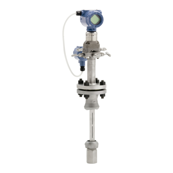
June 2016 Quick Start Guide NOTICE This guide provides basic guidelines for Rosemount 485 Annubar. It does not provide instructions for configuration, diagnostics, maintenance, service, troubleshooting, Explosion-proof, Flameproof, or Intrinsically Safe (I.S.) installations. Refer to Rosemount 485 Annubar Reference Manual for more instruction. - Page 3 Quick Start Guide June 2016 Figure 1. Rosemount 485 Annubar Flange Assembly Exploded View A. 2 O-rings G. Transmitter B. Direct mount transmitter connection with valves H. Coplanar flange with drain vents C. Studs I. Sensor flange D. Gasket J. Mounting flange assembly E.
-
Page 4: Location And Orientation
June 2016 Quick Start Guide 1.0 Location and orientation Correct orientation and straight run requirements must be met for accurate and repeatable flow measurements. Refer to Table 1 for minimum pipe diameter distances from upstream disturbances. Table 1. Straight Run Requirements In plane____________Out of plane Upstream pipe diameters Without... - Page 5 Table 1 applies to gate, globe, plug, and other throttling valves that are partially opened, as well as control valves. 1.1 Misalignment Rosemount 485 Annubar installation allows for a maximum misalignment of 3°. Figure 2. Misalignment ±3° ±3° ±3°...
- Page 6 June 2016 Quick Start Guide 1.2 Horizontal orientation For proper venting and draining, the sensor should be located in the upper half of the pipe for air and gas applications. For liquid and steam applications, the sensor should be located in the bottom half of the pipe. The maximum temperature for a direct mounted transmitter is 500 °F (260 °C).
- Page 7 Quick Start Guide June 2016 1.3 Vertical orientation The sensor can be installed in any position around the circumference of the pipe, provided the vents are positioned properly for bleeding or venting. Optimal results for liquid or steam are obtained when flow is up. For steam applications, a 90°...
-
Page 8: Drill Sensor Holes
Drill to Hole Size P/N: 28-109001-922 Rev. AC ™ When drilling the mounting hole(s), Emerson Process Management recommends the use of a magnetic drill or pipe clamping fixture to safely drill the hole. Use appropriate personal protective equipment and procedures when drilling and welding. -
Page 9: Assemble And Check Fit-Up
For accurate measurement, use the following steps to ensure that Ports A and B are equal distances from the inside walls of the pipe. 1. Assemble the Rosemount 485 to the mounting hardware with the gaskets and bolts. 2. Hand tighten the bolts just enough to hold the position of the sensor centered in the mounting hardware. - Page 10 June 2016 Quick Start Guide Figure 5. Fit-up Check for Rosemount 485 Annubar with Opposite-Side Support Liquid or steam A. The same with -in. (3 mm) D. Outer Diameter to Flange (ODF) B. Port A E. Pipe outside diameter C. Port B...
-
Page 11: Weld Mounting Hardware
Quick Start Guide June 2016 4.0 Weld mounting hardware 1. Center the flanged assembly over the mounting hole, gap -in. (1,6 mm), and measure the distance from the outer diameter of the pipe to the face of the flange. Compare this to Table 3 and adjust the gap as necessary. -
Page 12: Insert The Rosemount Annubar Sensor
June 2016 Quick Start Guide 3. If opposite-side support is being used, center the fitting for the opposite side support over the opposite side hole, gap -in. (1,6 mm), and place four -in. (6 mm) tack welds at 90° increments. Insert the sensor into the mounting hardware. - Page 13 Quick Start Guide June 2016 6.2 Transmitter mounting with remote mount head Temperatures in excess of 250 °F (121 °C) at the sensor module diaphragms will damage the transmitter. Remote mounted transmitters are connected to the sensor by means of impulse piping, which allows process temperatures to decrease to a point where the transmitter is no longer vulnerable.
- Page 14 June 2016 Quick Start Guide Figure 7. Valve Identification for 5-Valve and 3-Valve Manifolds 5-valve manifold 3-valve manifold To PH To PL To PH To PL Table 4. Description of Impulse Valves and Components Name Description Purpose Components Transmitter Reads Differential Pressure Manifold Isolates and equalizes electronics Manifold and impulse valves...
- Page 15 Quick Start Guide June 2016 6.3 Recommended installations for remote mount transmitters Gas service Secure the transmitter above the sensor to prevent condensable liquids from collecting in the impulse piping and the DP cell. Figure 8. Gas Service Vertical gas Horizontal gas...
- Page 16 June 2016 Quick Start Guide Steam or liquid service Mount the transmitter below the process piping, adjust 10 to 15 degree above direct vertical down. Route the impulse piping down to the transmitter and fill the system with water through the two cross fittings. Figure 9.
- Page 17 Quick Start Guide June 2016 Top mounting for steam service This orientation can be used for steam at any temperature. However, it is required for installations above 600 °F (315 °C). For remote mount installations the impulse piping should slope up slightly from the instrument connections on the Rosemount Annubar to the cross fittings allowing condensate to drain back into the pipe.
-
Page 18: Product Certifications
A hard copy may be obtained by contacting our local sales office. European Pressure Equipment Directive (PED) (97/23/EC) Rosemount 485 Annubar — Refer to EC declaration of conformity for conformity assessment Pressure Transmitter — See appropriate Pressure Transmitter QSG 7.3 Hazardous Locations Certifications... - Page 19 Quick Start Guide June 2016 Figure 11. Rosemount Primary Element Declaration of Conformity...
- Page 20 June 2016 Quick Start Guide...
- Page 21 Quick Start Guide June 2016...
- Page 22 June 2016 Quick Start Guide China RoHS Rosemount 485 表 表 格 含有 管控物 超 的部件型号列表 Table 1B: List of Rosemount 485 Parts with China RoHS Concentration above MCVs 有害物 Hazardous Substances 部件名称 多 Part Name 六价 多 汞 Polybrominated...
- Page 23 Quick Start Guide June 2016...
- Page 24 Standard Terms and Conditions of Sale can be found at Emerson FZE P.O. Box 17033, www.Emerson.com/en-us/pages/Terms-of-Use.aspx Jebel Ali Free Zone - South 2 The Emerson logo is a trademark and service mark of Emerson Dubai, United Arab Emirates Electric Co. Annubar, Rosemount and Rosemount logotype are trademarks of +971 4 8118100 Emerson Process Management.
Need help?
Do you have a question about the Rosemount 485 and is the answer not in the manual?
Questions and answers