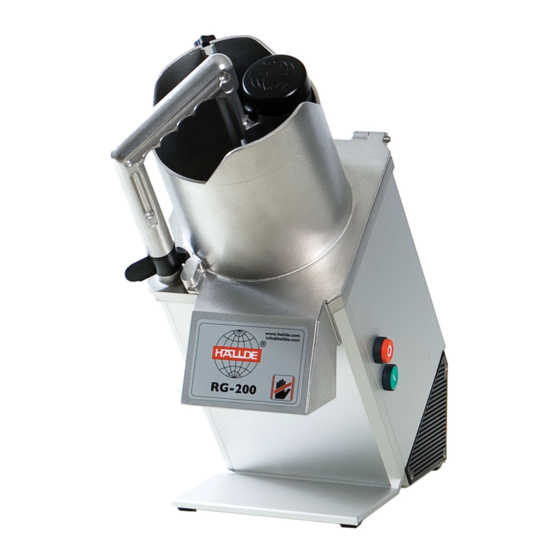
Hallde RG-200 Service Manual
Vegetable preparation machine
100 – 230 v single phase
Hide thumbs
Also See for RG-200:
- User instructions (7 pages) ,
- User instructions (25 pages) ,
- User instruction (30 pages)

Related Manuals for Hallde RG-200


Summary of Contents for Hallde RG-200
- Page 1 Service Manual Vegetable Preparation Machine RG-200 100 – 230 V Single Phase Date: 2015-08-27 Approved: Henrik Artursson...
-
Page 2: Table Of Contents
Table of contents GENERAL ........................3 Installation, operation and cleaning..........................3 Tools....................................3 Lubrication and thread locking............................3 REMOVAL AND REPLACEMENT OF PARTS..............2 Machine housing panels..............................2 On and Off switches................................. 3 Feed hopper switch................................4 Pusher plate switch................................4 RC Network..................................5 Contactor ................................... -
Page 3: General
General This service manual gives instructions for removal and replacement of parts including service procedures and adjustments for the vegetable preparation machine RG-200. This service manual is prepared for the use of trained service technicians and should not be used by those not properly qualified. -
Page 4: Removal And Replacement Of Parts
Removal and replacement of parts Machine housing panels Note! Disconnect the electric power to the machine! 1. Position the machine as shown and remove 4 access nuts to remove base. 4x access nuts 2. Remove base. Base 3. Carefully slide both housing panels up and clear of studs. -
Page 5: Onandoff Switches
4. Reassemble in reverse order OnandOff switches Note! Disconnect the electric power to the machine! 1. Remove right side machine housing panel as outlined under MACHINE HOUSING PANELS. 2. Lift the locking tab to release switch from actuator body. Switch Locking tab Actuator body 3. -
Page 6: Feedhopperswitch
4. Unscrew retaining ring from actuator body then remove actuator from machine. 5. Reassemble in reverse order and check for proper operation. When installing a replacement switch, press the switch onto actuator body until locking tab snaps into place to secure. Feedhopperswitch Note! Disconnect the electric power to the machine! 1. -
Page 7: Rcnetwork
2. Disconnect lead wires from switch. 3. Remove 2 screws to remove switch and mounting plate from machine. 2x screw 4. Reassemble in reverse order. If switch adjustment is necessary, the hole tolerance for the switch mounting bracket is the only available adjustment. The switch should open when pin engages roller. -
Page 8: Contactor
RC network Contactor 3. Disconnect lead wires from contactor. 4. Reassemble in reverse order and check for proper operation. Contactor Note! Disconnect the electric power to the machine! 1. Remove right side machine housing panelas outlined under MACHINE HOUSING PANELS. 2. -
Page 9: Motor Capacitor
Motorcapacitor Note! Disconnect the electric power to the machine! 1. Remove machine housing panels as outlined under MACHINE HOUSING PANELS. 2. Pry off protective cap. 3. Discharge capacitor by shorting terminals. 4. Disconnect lead wires from capacitor. 5. Remove capacitor from motor plate. When installing a replacement capacitor, remove threaded insert from bottom of original capacitor then install on replacement capacitor. - Page 10 Guide pin Switch actuator Retaining ring 3. Remove guide pin from shaft. Note! Pin is secured with Loctite and will be very tight. Apply Loctite 243 to threads of guide pin when reinstalling pin. 4. Remove pusher plate assembly. 5. Remove seal. Note! When new seal is installed, apply a light coat of mineral oil to inside surface of seal.
-
Page 11: Motor
7. Reassemble in reverse order and check for proper operation. Motor Note! Disconnect the electric power to the machine! 1) Remove machine housing panels as outlined under MACHINE HOUSING PANELS. 2) Remove 4 torx screws securing the motor mounting plate. 4x torx screws 3) To replace motor a) Remove 4 screws securing mounting plate to motor. -
Page 12: Planetarygears
Note! These screws are secured with Loctite and will be very tight. Ally Loctite 243 to the screw s threads when reinstalling. b) Disconnect motor lead wires. c) Remove capacitor d) Reassemble in reverse order and check for proper operation. Planetarygears Note! Disconnect the electric power to the machine! 1) Remove ring gear by lifting out. - Page 13 Ejector pin Seal washer 3) Remove 3 screws securing planetary assembly. 3x screws 4) Remove planetary assembly by tapping on knife shaft with brass or plastic hammer. 5) Remove and replace shaft seal.
- Page 14 6) Remove socket head screw. Note! Parts are under spring pressure. Hold in place while removing screw. Screw is secured with Loctite and will be very tight. Apply Loctite to threads of screw when reassembling. 7) Remove planetary washer (retaining ring) then lift planetary wheel from shaft. 8) Reassemble in reverse order and check for proper operation.
-
Page 15: Sealwasher
Sealwasher Note! Disconnect the electric power to the machine! 1. Remove guide pin from knife shaft. 2. Remove seal washer from knife shaft. Ejector pin Seal washer 3. To install: a. Lubricate seal washer with food safe lubricant then place the seal washer onto knife shaft with the beveled side up. -
Page 16: Service Procedures And Adjustments
Service Procedures and Adjustments Electrical controls testprocedure 1. Remove cutting tools. 2. Connect food processor to the proper voltage source. 3. Close feed hopper and position pusher plate into the feed hopper. 4. Press ON button and motor should start. 5. -
Page 17: Electrical Operation
Electrical Operation Componentfunction Motor Turns cutting tool to slice product. Protected by thermal overload with auto reset. Contactor Controls power to motor. ON Switch Provides initial power to control circuit (momentary on). OFF Switch Removes power from control circuit (momentary off). Feed Head Switch Ensures feed hopper is down (feed switch closed) before food processor operation can begin. -
Page 18: Component Location
Component location Motor capacitor on back side of motor On and Off switches on right side panel RC Network Motor Contactor Pusher plate switch Feed head switch Sequence of operation 1. Conditions. a. Machine properly connected to power and properly grounded. b. -
Page 19: Electricaldiagram
4. If stop switch is pressed, contactor is de-energized and motor stops. 5. If pusher plate switch is opened, motor stops. 6. Latching circuit remains energized so that motor restarts when pusher plate switch is closed. Electricaldiagram See user instructions and www.hallde.com for applicable electric diagram. -
Page 20: Troubleshooting
Troubleshooting SYMPTOM POSSIBLE CAUSES Motor will not start, feed head is down and 1. No voltage to machine. pusher plate is in operating position. 1OL tripped - current setting incorrect; or auto reset not selected; or malfunction. 3. Feed hopper switch (1LS) malfunction. 4.
Need help?
Do you have a question about the RG-200 and is the answer not in the manual?
Questions and answers