Table of Contents
Advertisement
Advertisement
Table of Contents

Related Manuals for Simrad R2009


Summary of Contents for Simrad R2009
- Page 1 R2009/R3016 User Manual ENGLISH...
- Page 2 Note: This manual does not cover installation of the various antennas that can be used in these radar systems. In addition to this manual the following documents are available for the R2009 and R3016 Control units: • R2009/R3016 Quick Guide (988-10951-00n) •...
- Page 3 Only reading these operating instructions cannot replace such training. Persons authorized to operate, maintain and troubleshoot the system are instructed and trained by Simrad. Persons operating or servicing this radar system must be familiar with the general safety regulations and specific safety systems, and they must have passed all required training.
- Page 4 SD-3C, LLC in the United States, other countries or both. ® ™ HDMI and HDMI , the HDMI Logo, and High-Definition Multimedia Interface are trademarks or registered trademarks of HDMI Licensing LLC in the United States and other countries. Preface | R2009/R3016 User manual...
-
Page 5: Table Of Contents
Contents Introduction R2009 and R3016 Radar Control units O2000 Controller System diagrams 11 The user interface Front panel and keys Main panel PPI symbols Picture freeze indicator Softkeys The menu system Measurements units Radar palettes On-screen keyboard Screen capture 17 Basic operation... - Page 6 Backing up your system data 62 The alert system Type of alerts Alert notifications Acknowledging alerts The Alerts dialog Alphabetic alarm listing Operating modes fallback 66 Terms and abbreviations 70 Spare parts and accessories R2009 Options and accessories Contents | R2009/R3016 User manual...
- Page 7 R2009 Spare parts and service packs R3016 Options and accessories R3016 Spare parts and service packs 72 Technical specifications Overview Display Technical/environmental Power Compass safe distance 74 Menu tree 75 Dimensional drawings R2009 Control unit R3016 Control unit Contents | R2009/R3016 User manual...
-
Page 8: Introduction
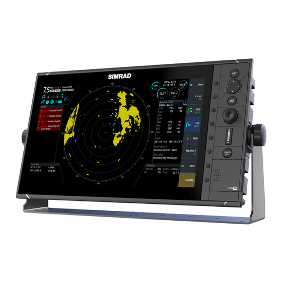
16-inch widescreen display. The units are compatible with a range of Simrad radar solutions, including Halo™ Pulse Compression, Broadband 3G™/4G™, and HD Digital radars. The R2009 is fitted with a high brightness screen and is suited for both pilot house and outside installation. The R3016 is suited to pilot house installation only. -
Page 10: The User Interface
Standby/Brilliance (STANDBY/BRILL) key Press once to display the Brilliance/Standby pop-up, press again to toggle between Standby and Transmit mode. Press and hold to switch the radar system on/off. Card reader door SD card reader The user interface | R2009/R3016 User manual... -
Page 11: Main Panel
Target panel Detailed information about selected targets and AIS targets. Softkey bar Reference for softkey functions. Target indicators Overview of target indicator settings. Markers Details for active VRM and EBL markers. The user interface | R2009/R3016 User manual... -
Page 12: Ppi Symbols
The Own ship information area includes a picture freeze indicator (A). The small dot blinks at an interval of 1 second to show that the screen is alive and that information from sensors are updated. If the picture freezes the R3016 Control unit needs to be restarted. The user interface | R2009/R3016 User manual... -
Page 13: Softkeys
Sub-menu indication Selected menu item Settings dialogs The various Settings dialogs provide access to system settings and for vessel specific settings. You access the Settings dialogs from the Main menu. The user interface | R2009/R3016 User manual... -
Page 14: Measurements Units
Measurements units can only be changed when the connected antenna is in standby. Radar palettes Different palettes are available for the radar video and for the target trails. You select the palettes from the Radar Settings dialog. The user interface | R2009/R3016 User manual... -
Page 15: On-Screen Keyboard
You remove the virtual keyboard without entering information by pressing the EXIT key. Screen capture Simultaneously press the ENT and Power/Brilliance keys to take a screen capture. Screen captures are saved to internal memory. To view files, refer to "Files" on page 48. The user interface | R2009/R3016 User manual... -
Page 16: Basic Operation
Note: The R2009 Control unit can be wired and configured for power control. If the unit is configured as a power slave, the unit will turn on and off when the power master is turned on and off. Refer to "Power Control" on page 48. -
Page 17: Target Tracking
If the sensor measures only the longitudinal component of the speed, the transversal ship component is unknown to the radar. EPFS The EPFS provides True Speed and True Course Over Ground. Basic operation | R2009/R3016 User manual... -
Page 18: Adjusting The Radar Image
If the value is increased too much, both sea clutter and targets will disappear from the display and targets around own ship may not show potentially dangerous targets. Adjusting the radar image | R2009/R3016 User manual... -
Page 19: Tune
(range set to 24 NM), and by using a high level of gain. In this condition, adjust the tuning control to obtain the maximum signal strength. You adjust the tuning from the Tune sub-menu. Adjusting the radar image | R2009/R3016 User manual... -
Page 20: Radar View Options
In Relative motion your vessel remains in a fixed location on the Radar PPI, and all other objects move relative to your position. You select the position of the fixed location as described in "Offsetting the PPI center" on page 22. Radar view options | R2009/R3016 User manual... -
Page 21: Offsetting The Ppi Center
PPI center is immediately moved to the cursor position. Vectors A target vector indicates the expected target movement within a defined time. The vectors are computed by multiplying the target speed with the set time value. Radar view options | R2009/R3016 User manual... -
Page 22: Cursor Bearings
VRM EBL One EBL/VRM, EBL - 0.25 NM; VRM - 0 Range 6 NM Range rings Orientation North up Motion mode True Off-centering Look ahead Speed source EPFS; Stabilization - Ground Past position Radar view options | R2009/R3016 User manual... -
Page 23: Target Tracking
Press and hold the ENT key to display the Cursor ENTER menu, the select the Acquire target menu option There might be a delay after having selected the target before the system received stable target data: Target tracking | R2009/R3016 User manual... - Page 24 You can set the length of the trails. The length represents the time it takes for the trails to fade out. The Clear trails option clears target trails from your radar panel temporarily. The trails start to build up again unless you switch the function off. Target tracking | R2009/R3016 User manual...
- Page 25 The problem can usually be eliminated or strongly reduced by an accurate adjustment of the Sea control. Refer "Sea anti-clutter" on page 19. Target tracking | R2009/R3016 User manual...
-
Page 26: Ais Targets
Lost AIS target, indicated with crossed lines centered on the target symbol. The symbol is located at the last received position from the target. Note: A symbol is drawn with a dotted line if the collision avoidance cannot be calculated. Target tracking | R2009/R3016 User manual... -
Page 27: Displaying Target Information
When you select a radar or an AIS target, the Target panel changes to show detailed information for the selected target. This information remains in the Target panel until the target is de-selected. Target panel - no targets selected Target panel - AIS target selected Target tracking | R2009/R3016 User manual... - Page 28 The Vessels dialog displays a list of all tracked targets. The dialog is activated from the TT/AIS menu. This dialog lists targets by distance to own vessel, but allows for sorting the targets based on target name. The dialog also lists received AIS messages. Target tracking | R2009/R3016 User manual...
-
Page 29: Navigation Tools
• EBM/VRM1 is cyan • EBL/VRM2 is blue The EBL presentation can be defined with true or relative presentation: Navigation tools | R2009/R3016 User manual... - Page 30 When an EBL/VRM marker is in edit mode, the following options are available for adjusting the marker: • use the arrow keys to move the EBL/VRM intersection • turn the rotary knob to adjust the adjustable parameter (bold line and blue text in softkey) Navigation tools | R2009/R3016 User manual...
-
Page 31: Measuring Range And Bearing
System Information are on the radar image. The range scales, the related distance between the range rings and number of rings are: Range (NM) Distance between the Number of range rings range rings (NM) 1/40 1/20 1/10 Navigation tools | R2009/R3016 User manual... - Page 32 - Range and bearing from the EBL/VRM marker's center to cursor position is now displayed in the Markers panel You can reset the EBL/VRM marker's center to vessel position by selecting the Reset offset option in the EBL/VRM pop-up. Navigation tools | R2009/R3016 User manual...
-
Page 33: Advanced Radar Options
Interference could be caused by radar signals from other radar units operating in the same frequency band. A high setting reduces the interference from other radars. In order not to miss weak targets, the interference rejection should be set to low when no interference exists. Advanced radar options | R2009/R3016 User manual... -
Page 34: Noise Rejection
(separation between objects is more prominent). Fast scan Sets the speed of the radar antenna rotation (from 20 RPM in standard mode to 36 RPM in Fast scan mode). This option gives faster target updates. Advanced radar options | R2009/R3016 User manual... -
Page 35: Installation
Fixing screws Documentation pack U-brackets U-bracket straps (one for R2009, two for R3016) Mounting location Choose the mounting locations carefully before you drill or cut. The unit should be mounted so that the operator can easily use the controls and clearly see the screen. -
Page 36: Viewing Angle
Do not mount the R3016 in an outside location exposed to direct sunlight, it is intended for pilothouse installation only. The R2009 may be mounted both inside, or outside in direct sunlight due to a high brightness screen. Ensure that any holes cut are in a safe position and will not weaken the boat’s structure. If in doubt, consult a qualified boat builder, or marine electronics installer. -
Page 37: U-Bracket Mounting
Fix the bracket straps. Panel mounting The screws and gasket used for panel mounting are included in the box. For mounting instructions, refer to the Panel mounting template. Installation | R2009/R3016 User manual... -
Page 38: Wiring
ETHERNET NMEA2000 POWER NMEA0183 1 3 4 5 R2009 Rear connections ETHERNET HDMI NMEA2000 POWER NMEA0183 NMEA0183 2 3 4 5 6 R3016 Rear connections Ethernet, 5-pin HDMI (available on R3016 only) NMEA 2000, 5-pin Power, 4-pin Wiring | R2009/R3016 User manual... -
Page 39: Ethernet Connector
2 A for the 9" model and 5 A for the 16" model. Unit socket (male) Cable plug (female) Purpose Color -12/24 VDC Black External alarm Blue Power control (R2009), Return for blue wire isolated signal Yellow (R3016) +12/24 VDC Wiring | R2009/R3016 User manual... -
Page 40: External Alarm
Master unit are connected (power control bus). Note: If the R2009 is set to Power Slave, the unit cannot be powered down using its own POWER/BRILL key. Pressing and holding this key will set the unit to standby. Refer to "Power Control"... -
Page 41: Nmea 2000 Backbone
The NMEA 2000 data port allows the receiving and sharing of a multitude of data from various sources. Unit socket (male) Cable plug (female) Purpose Color Shield Drain NET-S (+12 VDC) NET-C (- 12 VDC) Black Wiring | R2009/R3016 User manual... - Page 42 The following drawing demonstrates a typical small network. The backbone is made up of directly interconnected T-connectors. 12 V DC NMEA 2000 device Connector to unit Drop-cable, should not exceed 6 m (20 ft) Terminators Backbone Power cable Wiring | R2009/R3016 User manual...
-
Page 43: Nmea 0183 Device Connection
38,400 baud. For configuring of the ports, refer to "Serial ports" on page 51. • The R2009 unit has one NMEA 0183 serial port, providing two inputs and two outputs. Cable used: NMEA 0183 serial cable. •... - Page 44 Talker B (Tx+) Brown Port 1 Port 3 Talker A (Tx-) White Port 1 and Port 3 Shield Bare wire Port 1 Port 3 Listener A (Rx-) Yellow Port 1 Port 3 Listener B (Rx+) Green Wiring | R2009/R3016 User manual...
-
Page 45: Connect An External Monitor
HDMI amplifier or use HDMI-CAT6 adaptors. Note: Some HDMI TV displays may apply over-scan, which will in effect crop the image possibly causing loss of important content. Check the display manual for an option to disable over-scan or adjust scaling Wiring | R2009/R3016 User manual... -
Page 46: Software Setup
Radar Settings. Refer "Radar settings" on page 52 Own vessel charachteristics. Refer "Own ship" on page 57 System settings Use the system settings dialog to set basic settings as described below. Some settings can require a reboot of the system. Software setup | R2009/R3016 User manual... -
Page 47: Network Settings
Note: This option is available for R2009 Control units only. Used for defining the R2009 Control unit as a power slave. This setting is only applicable if the yellow wire is connected to ignition or to a stand-alone switch that applies 12 V/24 V. - Page 48 ‘Auto select’ selected source is not the one desired. Device list The Device list shows the devices that provide data. This may include a module inside the unit, or any external NMEA 2000 device. Software setup | R2009/R3016 User manual...
- Page 49 Rx Overflows The unit received too many messages for its buffer before the application could read them. Rx Overruns The unit contained too many messages for its buffer before the driver could read them. Software setup | R2009/R3016 User manual...
- Page 50 Specifies the baud rate for port for the devices connected to the NMEA 0183. The baud rate should be set to correspond with devices connected to the NMEA 0183 input and output. The input and output (Tx, Rx) use the same baud rate setting. Software setup | R2009/R3016 User manual...
-
Page 51: Radar Settings
All options are described in the next sections. Option 10 kW 25 kW 3G Halo Radar source Radar status Antenna setup Adjust range offset Adjust bearing alignment Sector blanking Sidelobe suppression Tune Software setup | R2009/R3016 User manual... - Page 52 If this is set incorrectly, a large dark circle in the center of the sweep might occur. You might notice straight objects such as straight sea walls Software setup | R2009/R3016 User manual...
- Page 53 Sidelobe suppression Occasionally false target returns can occur adjacent to strong target returns such as large ships or container ports. This occurs because not all of the transmitted radar energy can be Software setup | R2009/R3016 User manual...
- Page 54 The accent lighting can only be adjusted when the radar is in standby mode. Note: The blue accent pedestal lighting might not be approved for use in your boating location. Check your local boating regulations before turning the blue accent lights ON. Software setup | R2009/R3016 User manual...
- Page 55 80% or lower. View from left Note: This option is available for the R2009 control unit only. Used for optimizing the display for viewing from the left. See "Viewing angle" on page 37. Software setup...
-
Page 56: Own Ship
- Sets the approximate location for the primary GPS position sensor. This is relevant to correct positioning of AIS targets on the PPI. MMSI Set the vessel’s own MMSI number. This prevents the vessel being identified as an AIS target on own display. Software setup | R2009/R3016 User manual... -
Page 57: Simulator
You can also use your own recorded log data files in the simulator. Advanced simulator settings The Advanced simulator settings allows for manually controlling the simulator. GPS source Selects where the GPS data is generated from. Simulator | R2009/R3016 User manual... - Page 58 GPS data including speed and course come from the selected source file. Set start position Allows you to enter coordinates as a starting position. Note: This option is only available when the GPS source is set to Simulated course. Simulator | R2009/R3016 User manual...
-
Page 59: Maintenance
PDF files), this may reduce the allowed file size for the log file. The system logs as much data as possible within the file size limitation, and then it starts overwriting the oldest data. Maintenance | R2009/R3016 User manual... -
Page 60: Software Upgrades
Backing up your system data It is recommended to regularly copy your system settings files as part of your back-up routine. The files can be copied to a card inserted in the card reader. Refer to "Files" on page Maintenance | R2009/R3016 User manual... -
Page 61: The Alert System
• Audible signal • Steady symbol and descriptive text Active - Alarm acknowledged • No audible signal • Flashing symbol and descriptive Rectified - not text acknowledged • No audible signal The alert system | R2009/R3016 User manual... -
Page 62: Acknowledging Alerts
All alerts remain in the Alerts panel until the reason for the alarm is rectified. The Alerts dialog The Alerts dialog includes a list of active alerts together with a historic listing of the last 100 alerts. All alerts in the Alerts dialog include a time stamp. The alert system | R2009/R3016 User manual... -
Page 63: Alphabetic Alarm Listing
Position unavailable RADAR FAIL Radar TXRX failure REF TGT Lost Reference target lost SOG FAIL Speed Over Ground failure Speed LOG FAIL Not used speed LOG failure Speed LOG FAIL Speed LOG failure The alert system | R2009/R3016 User manual... -
Page 64: Operating Modes Fallback
POSN Invalid Position input • POSN failure Unavailable Possible to display target Radar video RADAR FAIL information input failure based on AIS data • AIS input failure AIS FAIL The alert system | R2009/R3016 User manual... -
Page 65: Terms And Abbreviations
Closest Point Of Approach Central Processing Unit Course Course To Steer CURS Cursor DAY/NT Day/Night DECR Decrease Degrees Delete DGPS Differential Gps DISP Display DIST Distance DPTH Depth Dead Reckoning Digital Selective Calling Terms and abbreviations | R2009/R3016 User manual... - Page 66 Head Up Heading Heading Line Hours Input/Output Integrated Bridge System Identification Input INIT Initialization Integrated Navigation System Interference Rejection IRCS Integrated Radio Communication System Interswitch Kilometre Knots Label Limit LOST TGT Lost Target Terms and abbreviations | R2009/R3016 User manual...
- Page 67 Raster Chart Display System Echo Reference REF SOG Echo Reference Speed REL or R Relative Relative Motion RM (R) Relative Motion (Relative Trails) RM (T) Relative Motion (True Trails) Raster Navigational Chart Range Rate Of Turn Terms and abbreviations | R2009/R3016 User manual...
- Page 68 TRKG Tracking Tracking Time To Go Target separation TWOL Time To Wheel Over Line Transmit, Transmitter TX/RX Transceiver Uninterruptible Power Supply Variable Range Marker Vessel Traffic Services Wheel Over Line Wheel Over Point Terms and abbreviations | R2009/R3016 User manual...
-
Page 69: Spare Parts And Accessories
NMEA 2000 Cable, 1.8 m (6 ft) 000-0127-53 NMEA 2000 Cable, 4.6 m (15 ft) 000-0119-86 NMEA 2000 Power cable 000-0119-75 NEP-2 Network expansion 000-10029-001 R2009 Spare parts and service packs Item Part number O2000 Control unit 151-10369-001 R2009 Control unit 151-10366-001 Sun cover... -
Page 70: R3016 Spare Parts And Service Packs
SD service pack 000-12402-001 Case re-assembly kit 000-12404-001 SD door kit 000-12408-001 Dash mounting pack 000-12410-001 Bracket mounting pack 000-12412-001 High speed NMEA 0183 serial cable, 2 m (6.6 ft) 000-12393-001 Power cable 000-00128-001 Spare parts and accessories | R2009/R3016 User manual... -
Page 71: Technical Specifications
Screen brightness R2009 ≤1200 cd/m R3016 300 cd/m Networking capability R2009 2 x NMEA 0183, 1x NMEA 2000, 1x Ethernet R3016 4 x NMEA 0183, 1x NMEA 2000, 1x Ethernet Video integration R2009 None R3016 1x HDMI output (Supported resolutions: 1366 x 768) -
Page 72: Power
R3016 20 W Compass safe distance Safe distance to the Safe distance to the standard magnetic steering magnetic compass compass R2009 Control unit 0.34 m 0.25 m R3016 Control unit 0.65 m 0.43 m Technical specifications | R2009/R3016 User manual... -
Page 73: Menu Tree
≡ Target boost Cursor ENTER menu ≡ Target expansion Acquire target No target ≡ Target separation Cancel target Over target Fast scan mode [ √ ] Select/Deselect target Over target Select AIS Over AIS Menu tree | R2009/R3016 User manual... -
Page 74: Dimensional Drawings
Dimensional drawings R2009 Control unit 247 mm (9.72”) 224 mm (8.81”) 67 mm (2.63”) 111 mm (4.37”) 219 mm (8.62”) 135 mm (5.31”) R3016 Control unit 505 mm (19.88”) 455 mm (17.91”) 67 mm (2.63”) 477 mm (18.77”) 120 mm (4.72”)
Need help?
Do you have a question about the R2009 and is the answer not in the manual?
Questions and answers