Table of Contents
Advertisement
M A N U A L
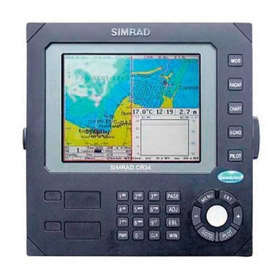
Simrad CR34/44/54
ChartRadar
183-3406-102 English 05082.20
Note!
Insert or remove C-MAP cartridges ONLY through SETUP menu or when
unit is off. All electronic navigation equipment is subject to external factors
beyond the control of the manufacturer. Therefore such equipment must be
regarded as an aid to navigation. The prudent navigator will, for that reason,
never rely on a single source for position fixing and navigation.
Advertisement
Table of Contents

Related Manuals for Simrad CR34


Summary of Contents for Simrad CR34
- Page 1 M A N U A L Simrad CR34/44/54 ChartRadar 183-3406-102 English 05082.20 Note! Insert or remove C-MAP cartridges ONLY through SETUP menu or when unit is off. All electronic navigation equipment is subject to external factors beyond the control of the manufacturer. Therefore such equipment must be regarded as an aid to navigation.
- Page 2 MOB ‘MAN OVERBOARD’ function In case someone falls overboard, press the [MOB] key and hold for 2 seconds (or activate an external MOB switch - hold for 5 seconds). Press [CLR] to confirm and reset the alarm if activated by mistake. Before pressing [ENT] to start MOB navigation: •...
-
Page 3: Table Of Contents
CR34/44/54 ChartRadar Table of contents MOB ‘MAN OVERBOARD’ function ......back of front cover Chapter 1 Introduction and safety summary Introduction and system familiarization ........1-1 Safety summary ................1-2 How to get started ................ 1-3 1.3.1 Dedicated function keys ............... 1-4 1.3.2... - Page 4 Table of contents CR34/44/54 ChartRadar 3.2.5 Standard radar display ..............3-11 3.2.6 Radar quick menu................3-17 3.2.7 RadarChart overlay................3-19 3.2.8 Dual radar display ................3-24 3.2.9 Radar & Chart display..............3-25 3.2.10 General features for the radar operation ..........3-26 Demo mode..................3-28 Chapter 4 Chart menu and INFO windows Chart menu ...................
- Page 5 CR34/44/54 ChartRadar Table of contents Position display................6-6 Dual speed display (trawling speed display) ........ 6-9 ETA & AVN ................6-10 Trim & Highway display ............6-11 Set & Drift display ..............6-12 Pilot split screens................ 6-13 Navigation examples ..............6-14 6.9.1...
- Page 6 Appendix A Glossary of terms ..............A-1 Appendix B List of datum ................B-1 Appendix C C-MAP attributes..............C-1 Index ................end of manual Declarations of conformity ............end of manual International warranty .............. end of manual List of Simrad distributors............end of manual...
-
Page 7: Introduction And System Familiarization
7” TFT (CR34), 10” ATFT/TFT (CR44) or 15” TFT (CR54) color display. The radar system with RadarChart overlay, dual EBL and VRM markers, direct Quick-range keys, off-center mode, etc. -
Page 8: Safety Summary
The lifetime of the internal battery is minimum 5 years. If not exchanged before it goes flat, all data in the unit’s memory will be lost. We strongly recommend that you frequently store your data on a Simrad DataCard. For exchange of battery, call your local Simrad workshop. -
Page 9: How To Get Started
CR34/44/54 Introduction and safety summary Chapter 1-3 1.3 How to get started When starting up for the very first time, the first time after loading a new software or after a master reset: Make sure that all hardware installation and electrical connections are completed in accordance to the installation instructions. -
Page 10: Dedicated Function Keys
Chapter 1-4 CR34/44/54 Introduction and safety summary Heading is only available if a compass was detected at start-up. Your present position will automatically be updated within a few min- utes. When ready, the ship symbol on the chart will flash, the position coordinates will stop flashing, and the *** will be replaced by actual course and speed figures. - Page 11 CR34/44/54 Introduction and safety summary Chapter 1-5 Long press will toggle between: ECHO Depth & temperature Custom screen diagram Short press will toggle between: PILOT Highway Position Dual Speed Set & Drift When navigation mode is active, these two displays will be included: ETA &...
-
Page 12: Radar And Radar Functions
Chapter 1-6 CR34/44/54 Introduction and safety summary 1.3.2 Radar and radar functions Press the [RADAR] key to call up a radar display. Press again to RADAR toggle between the radar shortcut series - see display examples in section 1.3.1. To start the radar 1. - Page 13 CR34/44/54 Introduction and safety summary Chapter 1-7 Select and adjust chart range/scale Press one of the numeric keys 1 - 9 to select a fixed range (and chart level). Key 9 will select the largest range and key 1 the smallest. Use the +/- keys to adjust range in smaller steps.
- Page 14 Chapter 1-8 CR34/44/54 Introduction and safety summary How to make a route on the chart 1. Place the cursor on the position for the first routepoint. 2. Press [PLOT], [4]: Make route. 3. Move cursor to next destination and press [PLOT] - (repeat).
- Page 15 CR34/44/54 Introduction and safety summary Chapter 1-9 • Without placing cursor on the symbol of the WP you wish to go to: 1. Press [GOTO], [2]. 2. Use the +/- keys to select the WP you wish to go to.
- Page 16 Chapter 1-10 CR34/44/54 Introduction and safety summary...
-
Page 17: Fundamentals Of The Display And
SIMRAD CR44 2.1 Fundamentals of the display and page system The CR34/44/54 ChartRadar has a multi-function screen and data presentation system with full screen and different types of split screens. The series of pages under the function keys (situated in a vertical row to the right of the display) will in most situations be suf- ficient information for the operator. -
Page 18: Example Of How To Exchange A Page In The
Chapter 2-2 CR34/44/54 Fundamentals & initial start-up Long press on the [PAGE] key will start a rotation of the four pages in intervals of 5 seconds (increase/decrease the time in [MENU], [7], [1]). Press any key to stop rotation. 2.1.1 Example of how to exchange a page in the PAGE system... -
Page 19: Key Functions
CR34/44/54 Fundamentals & initial start-up Chapter 2-3 Highlight a function e.g. Route calculation in the WP/RTE menu. Press [WIN] several times to check the screen image (situated to the far right in the top line of the menu bar) which windows the function... - Page 20 Chapter 2-4 CR34/44/54 Fundamentals & initial start-up Shortcut to Chart function. Short press will toggle between differ- CHART ent data fields on chart. Long press will toggle between Chart in full screen, Dual Chart, and two custom screens. Shortcut to Depth & temperature diagram and a custom screen.
-
Page 21: Menu Bar
CR34/44/54 Fundamentals & initial start-up Chapter 2-5 2.3 Menu bar Toggles the menu bar on/off MENU To fit the complete menu bar across the screen, some of the menus have been abbreviated. However, the last selected menu will be high- lighted, and if it’s an abbreviation of the menu, then the complete... -
Page 22: Menu Layout
Chapter 2-6 CR34/44/54 Fundamentals & initial start-up 2.4 Menu layout RADAR CHART ECHO Radar Chart Depth & temp.diagram Dual Radar Dual Chart Custom screen Radar & Chart Custom screen 1 Custom screen Custom screen 2 PILOT MISC WP/RTE Highway Wind... -
Page 23: Choice Of Symbols
CR34/44/54 Fundamentals & initial start-up Chapter 2-7 2.5 Choice of symbols Waypoints and other points appearing on the screen can be marked by one of 18 symbols + 8 event marks in small or large symbols: 2.6 Naming of routes, points etc. - Page 24 Chapter 2-8 CR34/44/54 Fundamentals & initial start-up Automatic input source setup ∆ Interface has not been set up! To start automatic input source setup, make sure that all connected products are turned ON, and press ENT. Start After making sure that all connected products are turned ON: Press [ENT] to start automatic input source setup, - if a new product is connected later on, refer to section 9.5 Interface setup.
-
Page 25: Turn Power On
CR34/44/54 Fundamentals & initial start-up Chapter 2-9 course and speed figures - see section 6.3 Position display. Do not start radar transmission before the antenna is warmed up, refer to section 3.2.3 Start transmission. Select display language: Call up the menu bar, and... - Page 26 Chapter 2-10 CR34/44/54 Fundamentals & initial start-up...
-
Page 27: Radar Operation
CR34/44/54 Radar menu Chapter 3-1 3. Radar operation The CRXX combines chart plotting with radar navigation. For first time users of Radar, we have included a basic description of the radar presentation with a basic understanding of how the controls affect the radar’s operation and display. -
Page 28: Orientation
Chapter 3-2 CR34/44/54 Radar menu 3.1.1 Orientation In the RELATIVE mode, the heading line always appears on the screen at 0° relative according to the on-screen bearing scale, and is coincident with the antenna beam passing the ship’s bow. Thus the top of the displayed picture represents the direction in which the ship is heading. -
Page 29: Environment Effects
CR34/44/54 Radar menu Chapter 3-3 tion move across the screen towards the edge of the display. Any other targets which are underway will also be moving on the display screen at their True course and True speed. All motion seen on the True motion display is “TRUE”... -
Page 30: Navigational Echoes
Chapter 3-4 CR34/44/54 Radar menu Overhead cable crossings can mimic a moving target on your radar screen. The cable target can appear to be on a collision course. The entire length of cable does not appear on the screen, only a point on the cable, and that point keeps changing giving the illusion of a moving target. -
Page 31: Sea Return
CR34/44/54 Radar menu Chapter 3-5 3.1.6 Sea return Not all radar echoes are produced by hard navigation items such as boats, buoys and land. Some radar echoes may be received from irregularities on the surface of the water, particularly at close range by breaking wavecrests, particularly in windy weather and in heavy seas. -
Page 32: Side Lobes
Chapter 3-6 CR34/44/54 Radar menu present. Darker sectors indicate possible shadowed areas. This infor- mation should be posted near the display unit, and operators must be alert for objects in these blind sectors. 3.1.9 Side lobes Echoes on the radar screen are not always the direct returns to the radar antenna. -
Page 33: False Echoes
CR34/44/54 Radar menu Chapter 3-7 3.1.11 False echoes Occasionally, echoes may appear on the screen at positions where there is no actual target. This type of target is called a False Echo. Sometimes they are known as Ghost Images, Indirect Echoes or Multiple Echoes depending on how they are generated. -
Page 34: Radar Menu
Chapter 3-8 CR34/44/54 Radar menu 3.2 Radar menu The Golden Rule! Today’s radars are packed full of neat features designed to make your cruising more enjoyable and safer. Use these features when you can, but remember the old axiom KISS (keep it simple sailor). -
Page 35: Shortcut To The Pages In The Radar-Series
CR34/44/54 Radar menu Chapter 3-9 3.2.1 Shortcut to the pages in the radar-series The RADAR function is one of the main functions in the CRXX. Each page under the [RADAR] key will include a window represent- ing the radar function. It is not possible to exchange main function displays with a new display. -
Page 36: Start Transmission
Chapter 3-10 CR34/44/54 Radar menu 3.2.3 Start transmission Normally, when starting the transmission, it will take approx. two minutes for the antenna to warm up and be ready for transmission. For initial start-up and after long storage, see below. Make sure nobody is standing close to the radar antenna when it... -
Page 37: Standard Radar Display
CR34/44/54 Radar menu Chapter 3-11 To resume the radar transmission: Call up the Radar quick menu Start transmission GOTO To shut down the radar function: Call up the Radar quick menu Turn ‘Power off’ RADAR 3.2.5 Standard radar display The standard radar display will require full screen presentation. - Page 38 Chapter 3-12 CR34/44/54 Radar menu Use cursor to activate and move the cross cursor on the radar back- ground - press [CLR] to remove cursor. Activate EBL-VRM1, and use cursor to move EBL-VRM1 around in the radar background - more details further ahead in this section - press [EBL] again, or [CLR] to remove EBL-VRM1.
- Page 39 CR34/44/54 Radar menu Chapter 3-13 RM (Relative Motion): The ship will stay in the center of the screen or at an offset position and targets will appear relative to own ship’s position. If receiving the alarm: “Heading missing” or “Position mising” the system will change to Head-Up in Relative Motion after 60 seconds and at the same time inform of “Changing to HeadUp”...
- Page 40 Chapter 3-14 CR34/44/54 Radar menu return to AUTO mode by pressing [CLR]. Press [CLR] to toggle between HBR (Harbor) and AUTO mode. Sea control – is used on the shorter ranges to suppress the effects of sea clutter close to own ship by reducing the nearby gain level.
- Page 41 CR34/44/54 Radar menu Chapter 3-15 after-glow or wake behind the moving targets or own ship. If the range scale is changed, the trails are cleared and new trails will be drawn on the screen. The trails are drawn for anything that moves on the screen, including sea gulls, sea clutter, buoys, and shoreline.
- Page 42 Chapter 3-16 CR34/44/54 Radar menu The guard zone is not available in the secondary radar display in Dual Radar mode. IR (Interference Rejection) – will reduce false echoes from other radars nearby, see section 3.1.10. Stretch – toggle between AUTO, ON, OFF.
-
Page 43: Radar Quick Menu
CR34/44/54 Radar menu Chapter 3-17 3.2.6 Radar quick menu From active radar display: Call up the Radar quick menu Radar quick menu Power On RADAR Transmit GOTO Activate EBL-VRM1 Activate EBL-VRM2 Activate Cursor Show Navigation Point Heading Line Clear Trails... - Page 44 Chapter 3-18 CR34/44/54 Radar menu Activate EBL-VRM2 A dotted line + circle will be drawn on the screen. Use the cursor key to move the EBL-VRM2 cursor. By placing the square cursor point over a target or over an object, it will indicate the distance to same.
-
Page 45: Radarchart Overlay
CR34/44/54 Radar menu Chapter 3-19 3.2.7 RadarChart overlay Radar and chart images merged into one presentation takes away the guesswork of interpreting radar information by providing the full picture. The overlay is a feature under the radar function, which con- sists of three layers of information. - Page 46 Chapter 3-20 CR34/44/54 Radar menu Color presets for the overlay display Different color combinations of radar targets and chart or radar background color are available: Call up the Light and power pop-up window Select a different number in the color Palette...
- Page 47 CR34/44/54 Radar menu Chapter 3-21 The tabs indicate which groups are available in each display mode e.g. in the above example, display mode, you have access to the OVERLAY groups in black: General, Areas and User data. The two groups in red i.e.
- Page 48 Chapter 3-22 CR34/44/54 Radar menu C-MAP features Overlay Full *Custom Simple Fishing Marine: Names Nav-Aids Light Sectors Attention Areas Tides, currents Nature of seabed Ports Tracks, routes Buoys Signals Land: Natural features rivers Natural features Cultural features Landmarks Chart: Grid...
- Page 49 CR34/44/54 Radar menu Chapter 3-23 Group: Areas - specifies the presentation of different areas on chart The default settings in this group are the same for all display modes and any change of the default settings will be applied in all display modes.
-
Page 50: Dual Radar Display
Chapter 3-24 CR34/44/54 Radar menu 3.2.8 Dual radar display MENU Call up the menu bar, and... load the Dual Radar display Standard radar display Secondary radar display This feature requires a full-screen presentation, with the standard display in the left half of the screen and the secondary radar display in the right half of the screen. -
Page 51: Radar & Chart Display
CR34/44/54 Radar menu Chapter 3-25 Carry out adjustments by using the same procedures as described in section 3.2.5 for the standard radar display, except for the guard zone which is not available in the secondary radar display. Indication of HDG (heading), Rpm (scanner rotation speed) and Pulse is only available in full screen presentation. -
Page 52: General Features For The Radar Operation
Chapter 3-26 CR34/44/54 Radar menu chart display, nothing will happen in the radar display, because the synchronization is ‘one way only’. The lock function is automatically activated when the required data is available. When the data is not available, the radar display and the chart display will both function as individual standard displays. - Page 53 CR34/44/54 Radar menu Chapter 3-27 • Radar colors - There are several color settings to choose from for the radar display. See Palette setup ([MENU],[7],[3]). • Range - The extension of the range depends on how powerful the connected radar antenna is. There are several ways of adjusting the...
-
Page 54: Demo Mode
Chapter 3-28 CR34/44/54 Radar menu Composition - materials such as metal and water are good reflec- tors. Others, such as wood and fiberglass are poor reflectors. 3.3 Demo mode For the purpose of a demonstration, the radar function has a demo mode, which can present a simulated radar picture without having a radar scanner connected. - Page 55 CR34/44/54 Radar menu Chapter 3-29 Bring the Demo mode in Standby: Call up Radar quick menu Go to Standby mode GOTO - this way you can easily return to the simulated radar picture by repeating the [ENT] and [GOTO] sequence.
- Page 56 Chapter 3-30 CR34/44/54 Radar menu...
-
Page 57: Chart Menu
CR34/44/54 Chart menu and INFO windows Chapter 4-1 4. Chart menu The displays obtained from this menu can easily be accessed from the main CHART function key [CHART] - Chart see section 4.1. Dual Chart Radar/chart overlay is accessed via the Custom screen 1 radar display - see section 3.2.7. -
Page 58: Data Field On Chart
Chapter 4-2 CR34/44/54 Chart menu and INFO windows From any display: CHART Long press on the [CHART] key will toggle between: Chart Dual Chart Custom screen 1 Custom screen 2 From full chart display: CHART Short press on the [CHART] key will toggle between different pres- entations of the data field on the chart e.g.:... -
Page 59: Ship Symbol
CR34/44/54 Chart menu and INFO windows Chapter 4-3 long, compass and depth indication, bearing and distance to either approach- ing point or cursor position; together with time and date in local or UTC. *)Refer to section 6.3 Status indicator and accuracy. -
Page 60: Range Or Zoom Function
Chapter 4-4 CR34/44/54 Chart menu and INFO windows 4.1.4 Range or zoom function With chart display active: Press one of the numeric keys to quickly change the chart scale: [1] = 1:600 [2] = 1:2,000 [3] = 1:6,000 [4] = 1:20,000... -
Page 61: Dual Chart Display
CR34/44/54 Chart menu and INFO windows Chapter 4-5 4.2 Dual Chart display It is possible to have two charts in different scales on the screen at the same time, one for detail and one for overview. Each chart can be operated individually, and each will have its own cursor and indi- vidual chart setup. - Page 62 Chapter 4-6 CR34/44/54 Chart menu and INFO windows 4.3 Chart custom screens The two custom screens in the chart menu consist of multiple window combinations e.g.: The displays, which are not related to the chart function, can be exchanged with a different one. It is also possible to change the right half of the screen from two quarter windows to half screen window, and vice versa.
-
Page 63: Chart Quick Menu
CR34/44/54 Chart menu and INFO windows Chapter 4-7 4.4 Chart quick menu Access the chart quick menu from active chart display. The func- tions available depends on the actual situation - refer to sections 4.4.1 to 4.4.7. 4.4.1 Cursor inactive... -
Page 64: Cursor Active But Not Placed On Any Object Or Data
Chapter 4-8 CR34/44/54 Chart menu and INFO windows 4.4.2 Cursor active but not placed on any object or data With chart in active window, and cursor active but not placed on any object or user data, press [ENT] to call up the quick menu with the... -
Page 65: Cursor Placed On Waypoint
CR34/44/54 Chart menu and INFO windows Chapter 4-9 4.4.3 Cursor placed on waypoint With chart in active window, and cursor placed on a waypoint, press [ENT] to call up the quick menu with the following to choose from: WP found Name: WP 1 LAT 57°15.504N... -
Page 66: Cursor Placed On Route Leg Or Line Section
Chapter 4-10 CR34/44/54 Chart menu and INFO windows 4.4.4 Cursor placed on route leg or line section With chart in active window, and cursor placed on a route leg or line section, press [ENT] to call up the quick menu with the following to... -
Page 67: Cursor Placed On Routepoint Or Linepoint
CR34/44/54 Chart menu and INFO windows Chapter 4-11 4.4.5 Cursor placed on routepoint or linepoint With chart in active window, and cursor placed on a routepoint or linepoint, press [ENT] to call up the quick menu with the following to choose from:... -
Page 68: Cursor Placed On Trackpoint
Chapter 4-12 CR34/44/54 Chart menu and INFO windows 4.4.6 Cursor placed on trackpoint Trackpoints are not as easily recognized as Routepoints, you may have to move the cursor along on the track to locate a trackpoint. With chart in active window, and cursor placed on a trackpoint,... -
Page 69: Cursor Placed On Target
CR34/44/54 Chart menu and INFO windows Chapter 4-13 4.4.7 Cursor placed on target With chart in active window, and cursor placed on a target symbol, press [ENT] to call up the quick menu with the following to choose from: Target found Name: TARGET 1 LAT 57°02.825N... -
Page 70: Goto Menu
Chapter 4-14 CR34/44/54 Chart menu and INFO windows 4.4.8 GOTO menu Call up the GOTO menu with access to navigation modes: GOTO Select NAV mode To select “Cursor” navigation will require that the chart cursor is active. Cursor “Waypoint”, “Route” and “Track” navi-... -
Page 71: Plot Menu
CR34/44/54 Chart menu and INFO windows Chapter 4-15 4.4.9 PLOT menu The CRXX is designed to make navigation easy and safe. Waypoints can easily be plotted with a single keystroke, or be inserted via the keypad. Making routes and drawing lines are done directly on the chart. - Page 72 Chapter 4-16 CR34/44/54 Chart menu and INFO windows the symbol (cf.section 2.5) and the color (select with +/- keys). Any changes made will be new presets for plotting/insertion of the cursor position. - From active chart display with cursor on: Same options as above, except that the zeroes in the position coordinates have been exchanged with the cursor position.
-
Page 73: Chart Setup
CR34/44/54 Chart menu and INFO windows Chapter 4-17 4.5 Chart setup The settings are dedicated to the chart in the active window and does not affect the second chart in dual chart mode. See section 3.2.7 for chart settings related to the RadarChart overlay. -
Page 74: Display Modes In The Chart Setup
Chapter 4-18 CR34/44/54 Chart menu and INFO windows Toggle between available settings Confirm changes and return to chart, or... Abandon Chart setup and return to chart without making any MENU changes 4.5.1 Display modes in the chart setup There are 7 different display modes to choose from: FULL (default), CUSTOM, SIMPLE, FISHING, LOW, GRID, and a special OVERLAY mode, which only can be activated from the radar function - see section 3.2.7. - Page 75 CR34/44/54 Chart menu and INFO windows Chapter 4-19 ..continued from previous page..C-MAP features Full *Custom Simple Fishing Land: Natural features rivers Natural features Cultural features Landmarks Chart: Grid AUTO AUTO AUTO AUTO AUTO Boundary lines AUTO AUTO AUTO Mixing levels Declutter Group: Depth - specifies the presentation of depth lines, levels, etc.
- Page 76 Chapter 4-20 CR34/44/54 Chart menu and INFO windows Group: Areas - specifies the presentation of different areas on chart. The default settings in this group are the same for all display modes and any change of the default settings will be applied in all display modes, except GRID, which do not include C-MAP features.
-
Page 77: Description Of Chart Features
CR34/44/54 Chart menu and INFO windows Chapter 4-21 4.5.2 Description of chart features Auto chart select - When sailing with ‘Auto chart select’ ON and cursor turned off, the range will automatically change to match the chart which is available. But when set to OFF, then the selected range will remain, also when sailing ‘out of the chart’. - Page 78 Chapter 4-22 CR34/44/54 Chart menu and INFO windows Land areas - can be set to FILLED or CONTOUR. FILLED= The land areas will be filled with a preset color in the Palette setup. CONTOUR= The land areas will be shown with a contour line only and the landfill will be the same as the background/water color on the chart.
- Page 79 CR34/44/54 Chart menu and INFO windows Chapter 4-23 Show range - can be set to WITH BACKGROUND, ON or OFF: WITH BACKGROUND - will add a small line to the chart display indicating that the length of the line equals a certain number of nautical miles/km - the indication is highlighted with a background color.
- Page 80 Chapter 4-24 CR34/44/54 Chart menu and INFO windows...
-
Page 81: Echo Menu
CR34/44/54 Echo menu Chapter 5-1 5. Echo menu ECHO Depth & temperature diagram Custom screen 5.1 Depth & temperature diagram MENU Call up the menu bar, and... activate Depth & temperature diagram Present water temperature and depth. Depth over time or dis- tance. - Page 82 Chapter 5-2 CR34/44/54 Echo menu Setup for Depth: Scale for depth: 0 -> Color for depth: Scale for temperature: 0 -> 20 °C Color for temperature: Interval of screen: TIME Time interval: 5 MIN. Go to the function you wish to change Key in new figures, or...
-
Page 83: Custom Screen
CR34/44/54 Echo menu Chapter 5-3 5.2 Custom screen MENU Call up the menu bar, and... call up the custom screen from Echo menu The displays, which are not related to the Echo function i.e. all dis- plays except the Depth & temperature diagram in the top left quarter of the screen, can be exchanged with a different one. - Page 84 Chapter 5-4 CR34/44/54 Echo menu...
-
Page 85: Pilot Menu
CR34/44/54 Pilot menu & navigation examples Chapter 6-1 6. Pilot menu PILOT Highway - see section 6.2 & 6.2.1 Position - see section 6.3 Dual Speed - see section 6.4 ETA & AVN - see section 6.5 Trim & Highway - see section 6.6... - Page 86 Chapter 6-2 CR34/44/54 Pilot menu & navigation examples Press the [PILOT] key from any display to call up a display in the pilot-series, and: PILOT Long press on the [PILOT] key will toggle between (default): Highway Custom screen 1 Custom screen 2 From one of the pilot displays i.e.
-
Page 87: Highway Display And Navigation Setup
CR34/44/54 Pilot menu & navigation examples Chapter 6-3 6.2 Highway display and Navigation setup MENU Call up the menu bar, and... load Highway display When there is no navigation mode active, you will receive the legend: NAVIGATION IS OFF. Before starting out in one of the navigation modes, it may be a good idea to check out the Navigation setup display and see if the default settings will suit your need. - Page 88 Chapter 6-4 CR34/44/54 Pilot menu & navigation examples The waypoint alarm will be activated when you reach the circle or the perpendicular line - WP line alarm - crossing through the waypoint. When “Auto waypoint shift” is set to “WP-circle” it will override the “WP circle alarm”...
-
Page 89: Highway Display When Navigation Mode Is Active
CR34/44/54 Pilot menu & navigation examples Chapter 6-5 6.2.1 Highway display when navigation mode is active MENU Call up the menu bar, and... load Highway display With navigation mode active, the highway display will provide a graphical steering display: Intended... -
Page 90: Position Display
Chapter 6-6 CR34/44/54 Pilot menu & navigation examples 6.3 Position display MENU Call up the menu bar, and... load the Position display Datum currently selected. Trip log 1 and 2. Position with three decimals in minutes. Speed over ground. Course, magnetic or true. - Page 91 CR34/44/54 Pilot menu & navigation examples Chapter 6-7 Status indicator and accuracy Small letters (a,b,c,) indicate that SA is active, and the position accuracy is expected to be better than 100 meters in 95% of the time. Capital letters indicate that SA is OFF, and the position accuracy is then expected to be 15 meters or better in 95% of the time.
- Page 92 Chapter 6-8 CR34/44/54 Pilot menu & navigation examples Key in new values, or... Toggle between available values Confirm editing and return to the Position display Datum - is preset to WGS 1984 (World Geodetic System 1984), but can be changed to any of the 118 datums listed in Appendix B e.g.
-
Page 93: Dual Speed Display (Trawling Speed Display)
CR34/44/54 Pilot menu & navigation examples Chapter 6-9 6.4 Dual speed display (trawling speed display) The analogue differential speed indicator will show how much the present speed varies from the average speed. If the difference exceeds +/- 3 knots (or km/h or miles/h), an arrow will appear which will be pointing out of the scale. -
Page 94: Eta & Avn
Chapter 6-10 CR34/44/54 Pilot menu & navigation examples 6.5 ETA & AVN display MENU Call up the menu bar, and... load the ETA & AVN display -to receive any data will require that navigation mode is active. ETA - Estimated Time of Arrival - refers to the inserted local time, and can be calculated to any point used for navigation. -
Page 95: Trim & Highway Display
CR34/44/54 Pilot menu & navigation examples Chapter 6-11 Go to AVN, and... Insert time and date Confirm entry 6.6 Trim & Highway display Some of the readings rely on data from external log and compass. The Trim & Highway display will provide information on actual and mean speed, velocity and water speed - see also section 6.7 Set &... -
Page 96: Set & Drift Display
Chapter 6-12 CR34/44/54 Pilot menu & navigation examples 6.7 Set & Drift display The readings rely on data from external log and compass. MENU Call up the menu bar, and... load the Set & Drift display Relative direction. True direction. - Page 97 CR34/44/54 Pilot menu & navigation examples Chapter 6-13 6.8 Pilot custom screens The two custom screens in thepilot menu consist of multiple window combinations e.g.: The displays presented in the example above are the default displays for Custom screen 1 under the PILOT menu.
-
Page 98: Navigation Examples
Chapter 6-14 CR34/44/54 Pilot menu & navigation examples 6.9 Navigation examples 6.9.1 Chart/cursor navigation. 6.9.2 Waypoint navigation. 6.9.3 Route navigation. 6.9.4 Track navigation. Relevant for all navigation modes are: - the highway display with graphical steering - section 6.2.1. - the ETA & AVN display with Estimated Time of Arrival and Approximate Velocity Necessary to reach a given point at a specific time - section 6.5. -
Page 99: Waypoint Navigation
CR34/44/54 Pilot menu & navigation examples Chapter 6-15 Next destination: While on the way, you can easily move the cursor to the next destination, and when ready to change navigation leg... GOTO Call up the GOTO menu Restart to approaching point - a new course line will be drawn from ship’s position to destination. -
Page 100: Route Navigation
Chapter 6-16 CR34/44/54 Pilot menu & navigation examples 6.9.3 Route navigation To start Route navigation will require that at least one route is stored in the memory. Refer to section 4.4.9 PLOT menu. There are two ways to start Route navigation: •... -
Page 101: Track Navigation
CR34/44/54 Pilot menu & navigation examples Chapter 6-17 routepoint. Pressing [GOTO] from chart display during navigation will activate GOTO an INFO window with the following functions to choose from: 1. Advance (to next routepoint) 2. Restart to approaching point (in case you have drifted off course) 3. - Page 102 Chapter 6-18 CR34/44/54 Pilot menu & navigation examples This will activate the pop-up window “Navigate in track” from where you can choose which track you wish to select for navigation: Scroll up/down in the track list until the correct track number / name...
-
Page 103: Anchor Guard
CR34/44/54 Pilot menu & navigation examples Chapter 6-19 6.10 Anchor guard GOTO Call up the GOTO menu, and... activate the anchor guard function -the chart display will provide an impression of the vessel’s position in relation to the alarm circle. - Page 104 Chapter 6-20 CR34/44/54 Pilot menu & navigation examples...
-
Page 105: Miscellaneous Menu
CR34/44/54 Miscellaneous menu Chapter 7-1 7. Miscellaneous menu MISC Wind - see section 7.1 Speed diagram - see section 7.2 Decca lanes - see section 7.3 Loran C - see section 7.4 Satellites - see section 7.5 DGPS - see section 7.6 SDGPS - see section 7.7... - Page 106 Chapter 7-2 CR34/44/54 Miscellaneous menu Load Setup for Wind display Setup for Wind: Damping level: MEDIUM Apparent wind scale: NORMAL Wind angle offset: 000° Show wind speed as: APPARENT Wind speed unit: METERS/SECOND Go to the function you wish to change Toggle between settings, or...
-
Page 107: Speed Diagram
CR34/44/54 Miscellaneous menu Chapter 7-3 7.2 Speed diagram MENU Call up the menu bar, and... load “Speed diagram” S= Speed over ground. V= Velocity towards waypoint. W*= Speed through water. SD (Set and drift)*= Speed and direction, true or relative. - Page 108 Chapter 7-4 CR34/44/54 Miscellaneous menu The scale for the speed diagram can be adjusted in this display. Time interval can be set in 8 intervals from 1 minute to 3 hours and freeze. Go to the function you wish to change...
-
Page 109: Decca Lanes
CR34/44/54 Miscellaneous menu Chapter 7-5 7.3 Decca lanes MENU Call up the menu bar, and... load decca chain display Open for change Leaf through the available chains - see below. Confirm entry To change the position readouts to decca mode, see section 9.3 under Pilot/Position setup, where ‘Display position as’... -
Page 110: Loran C
Chapter 7-6 CR34/44/54 Miscellaneous menu 7.4 Loran C MENU Call up the menu bar, and... load Loran C chain display Open for change Leaf through the available chains - see listing below. If required, go to the slaves, and... Toggle between available slaves (not all chains have more than one slave) ...and it is possible to alter the figures in the time delay... -
Page 111: Satellite Status
CR34/44/54 Miscellaneous menu Chapter 7-7 7.5 Satellite status MENU Call up the menu bar, and... load satellite status display The display will show which satellites are currently being used for computation of data. It will show their position together with SNR - Signal to Noise Ratio. - Page 112 Chapter 7-8 CR34/44/54 Miscellaneous menu Position update alarm “Alarm” in the satellite status display is preset to “OFF”. If the received position data is invalid, the position shown in the position display will start to flash. A position update alarm can be set ON/...
-
Page 113: Dgps Information
CR34/44/54 Miscellaneous menu Chapter 7-9 7.6 DGPS information (optional) The DGPS - differential position corrections - can be provided from a built-in module, which is preset to full automatic operation, or from connected DGPS receiver - see “Status indicator” in position display. - Page 114 Chapter 7-10 CR34/44/54 Miscellaneous menu Status - can either be: LOCKED = locked on a beacon and receiving differential data. NOT LOCKED = not locked on a becon and receiving no differen- tial data. NOT INSTALLED = there is no built-in DGPS module in unit.
-
Page 115: Sdgps Information
CR34/44/54 Miscellaneous menu Chapter 7-11 7.7 SDGPS information The SDGPS - satellite differential GPS - is preset to full automatic operation, which means that the system will utilize the position cor- rections from either differential GPS stations (refer to section 7.6) or satellite differential GPS signals from WAAS, EGNOS or MSAS (refer to section 7.7.1). - Page 116 Chapter 7-12 CR34/44/54 Miscellaneous menu Uses corrections from - indicates which differential corrections (DGPS or SDGPS) are currently used for position determination. CHANNEL 1: sat.no. - indicates which satellite number and name is currently tracked/searched by channel 1, and what is the tracking state.
-
Page 117: Satellites In Sdgps System
CR34/44/54 Miscellaneous menu Chapter 7-13 7.7.1 Satellites in SDGPS system The SDGPS system consist of eight orbiting geostationary satel- lites and is designed to form a seamless global augmentation system consisting of Waas (USA), EGNOS (Europe) and MSAS (Japan). If all three parts would become operative at the same time, there would be no performance problem. - Page 118 7.8 DSC VHF info To receive an iDSC Alarm and Message from VHF will require that the CRXX is connected to a compatible Simrad VHF radiotel- ephone. The data is transmitted via NMEA or SimNet. The message from the VHF will appear in a pop-up window together with an acoustic alarm.
-
Page 119: Waypoints Stored In The Memory
CR34/44/54 Waypoint / route menu Chapter 8-1 8. Waypoint / route menu WP/RTE Waypoints - see section 8.1 Routes - see section 8.2 Route calculation - see section 8.3 Lines - see section 8.4 Tracks - see section 8.6 Targets - see section 8.7... -
Page 120: Delete Waypoints Via Menu
Chapter 8-2 CR34/44/54 Waypoint / route menu Insert name of waypoint you wish to edit, or... Leaf through waypoints with +/- keys or up/down cursor Open for editing Place the cursor on the function you wish to change Key in new figures, or... -
Page 121: Routes Stored In The Memory
CR34/44/54 Waypoint / route menu Chapter 8-3 8.2 Routes stored in the memory The route list will keep a record of all the saved routes in the system. It will provide information on number of waypoints in the route etc. - Page 122 Chapter 8-4 CR34/44/54 Waypoint / route menu This display provides information on course line, XTE line, route legs, routepoints etc. Call up the Edit route display - if you wish to make any changes. (Editing a route currently used for navigation is not possible) Setting the Course line to OFF in this display will make the route invisible on the screen.
- Page 123 CR34/44/54 Waypoint / route menu Chapter 8-5 If the XTE distance is not the same in all legs, the value will be *.* instead of the 00.10nm. Navigation mode can be either RHUMB- LINE or GREAT CIRCLE, or... if not set to the same in all legs in a route, the mode will be: COMPOSITE.
-
Page 124: Delete Route Via Menu
Chapter 8-6 CR34/44/54 Waypoint / route menu 8.2.1 Delete route via menu MENU Call up the menu bar, and... load route list display Select the route you wish to delete Call up the details on highlighted route Open for editing... - Page 125 CR34/44/54 Waypoint / route menu Chapter 8-7 the +/- keys and then press [CLR] to remove the point from the route. Display example: Save the route with [ENT] and go to the Edit display - or leave the function with [MENU] to abandon the route.
-
Page 126: Route Calculation
Chapter 8-8 CR34/44/54 Waypoint / route menu 8.3 Route calculation To stay well informed during navigation, the Route calculation display will provide information on how long it takes to go from one point to another, total distance, arrival time etc. -
Page 127: Lines Stored In The Memory
CR34/44/54 Waypoint / route menu Chapter 8-9 8.4 Lines stored in the memory The line list will keep a record of all the saved lines in the system. It will provide information on number of line sections in line etc. -
Page 128: Delete Lines Via Menu
Chapter 8-10 CR34/44/54 Waypoint / route menu Leaf through the line points by moving cursor up/down Call up the Edit line display - if you wish to make changes. Turning “Line” OFF will make the line drawing invisible on the screen. -
Page 129: Start / Stop Track
CR34/44/54 Waypoint / route menu Chapter 8-11 8.5 Start / stop track The track function will provide a track trailing the movement of your ship. As default from the factory, the first track is stored as TRACK 1, the next as TRACK 2 etc. -
Page 130: Tracks Stored In The Memory
Chapter 8-12 CR34/44/54 Waypoint / route menu Type of track line i.e. full, dotted, etc. has 9 different types to choose from in 15 different colors. To stop track: PLOT Call up the PLOT menu Load Stop track pop-up window Stop the highlighted track 8.6 Tracks stored in the memory... -
Page 131: Delete Tracks Via Menu
CR34/44/54 Waypoint / route menu Chapter 8-13 Open for change “Display track” can be set ON/OFF, where OFF will make it invis- ible on the screen. Turn ON to put it back on the screen. Toggle between available values Confirm changes... -
Page 132: Targets Stored In The Memory
Chapter 8-14 CR34/44/54 Waypoint / route menu 8.7 Targets stored in the memory The CRXX can display the bearing and distance of up to three targets at a time in relation to the vessel e.g. harbors or important navigational points. A target is a fixed point on the chart which can be plotted by the cursor or from the ship’s position - refer to section... -
Page 133: Delete Target Via Menu
CR34/44/54 Waypoint / route menu Chapter 8-15 Toggle between available values Confirm entry 8.7.1 Delete target via menu MENU Call up the menu bar, and... load target display Select the target you wish to delete Open for editing Delete target Confirm that you want to delete the selected target, if not sure: press [MENU] to exit the display without having made any changes. -
Page 134: Data Transfer Via Datacard Or Disc
How to perform data transfers via TL50 (including data from Ship- mate RS2500 Trackplotter) is described in the TL50 manual. Use the Simrad DataCard or TL50 Turbo Loader to make backup files of all the user data you have created plus the current setups in the internal memory of the unit. - Page 135 CR34/44/54 Waypoint / route menu Chapter 8-17 DataCard status Press [1] to find out what data (if any) is stored on the DataCard The capacity is divided into two databanks: DATABANK 1 and 2 which can hold approx. 2 x 450 Kb data. Toggle between the two databanks with the +/- keys.
- Page 136 CR34/44/54 unit via the Data transfer system. However, it is not immediately accessible to transfer data via Data- Card from the new model CR34/44/54 to the older model CR42, etc., as this would require an update of the CR42. - For more information, please contact an authorized Simrad dealer.
-
Page 137: List Of Criteria For Data Transfer In The Action Column
CR34/44/54 Waypoint / route menu Chapter 8-19 Press [MENU] to exit and *reboot (only if loading “Setup”) MENU *) When the system makes a ‘reboot’ the screen will turn black for a brief moment, then the system will re-start and automatically return to the active display which was on the screen before you made the transfer. -
Page 138: Data Transfer Via Pc Interface
Chapter 8-20 CR34/44/54 Waypoint / route menu 8.10 Data transfer via PC interface Data transfer to and from a route planning program on a Personal Computer can be made via NMEA connection (Refer to Optional connections in the Installation manual) by means of the standard NMEA0183 sentences WPL and RTE. - Page 139 CR34/44/54 Waypoint / route menu Chapter 8-21 CR34 example: WARNING! Normal NMEA communication will be interrupted. MENU Exit Accept Press [ENT] to accept warning and continue. NMEA (1) connection Transmit WPs Transmit routes Receive WPs and routes MENU Exit Transmit WPs...
- Page 140 Chapter 8-22 CR34/44/54 Waypoint / route menu Receive WPs and routes Press [7] to enable reception of waypoints and routes from the plan- ning program The transmission of waypoints and routes can now be activated from the PC program. The info window below will inform you of the progress of the reception of data by keeping an eye on the counter.
-
Page 141: Setup Menu
CR34/44/54 Setup menu Chapter 9-1 9. Setup menu SETUP RADAR Radar setup - see section 9.1 CHART C-MAP cartridges - see section 9.2 PILOT Pilot/Position setup - see section 9.3 Speed alarm, units & language - see section 9.4 Interface setup - see section 9.5... - Page 142 Chapter 9-2 CR34/44/54 Setup menu Example of Radar setup: Head-Up in Relative Motion Range= 0.50nm .50nm Power off, X-MIT Power off 0 Tuning Indicator AUTO Tune 0 *Tune, Gain, Sea: adjust with +/- keys, and press AUTO [CLR] to return to AUTOmatic mode.
- Page 143 CR34/44/54 Setup menu Chapter 9-3 Tuning reference: Normally there should be no need to adjust the Tuning reference. However, if sensitivity is poor or there are any symptoms at all suggesting improper tuning, you may need to make an adjustment: Choose a displayed range of 3nm or higher. Use cursor to go to the Tuning reference value.
- Page 144 Chapter 9-4 CR34/44/54 Setup menu refer to minimum (first set of numbers) and maximum (second set of numbers) allowed STC value, the automatic function will never use an STC outside this interval. The third set of numbers equals the sensitivity of the function. The higher the number (more sensibility), the more STC filter.
- Page 145 CR34/44/54 Setup menu Chapter 9-5 4. Set ‘Rain’ to minimum: move cursor to the ‘Rain’ bar, and adjust with +/- keys. Now you are ready to adjust the Sea Auto and Sea Harbor limits in the lower part of the Radar setup display: First set of 3 digits - minimum: Adjust to lowest figure with accept- able amount of sea clutter on screen.*...
-
Page 146: C-Map Cartridges
Chapter 9-6 CR34/44/54 Setup menu C-MAP cartridges UPPER Name: EAST DENMARK AND WEST SWEDEN Code: EN-C161.4 Date: 14/09/2002 LOWER Name: Code: Date: Exit Test MENU Press [ENT] to test the data on the C-MAP C-card If a C-card is defect, it must be removed before you can exit the display. -
Page 147: Pilot / Position Setup
CR34/44/54 Setup menu Chapter 9-7 9.3 Pilot / Position setup MENU Call up the menu bar, and... open the SETUP menu, and... load Pilot/Position setup display PILOT Pilot/Pos setup: Display position as: LAT/LON Start position: 56°57.000N 010°25.000E Speed and course filter level:... - Page 148 Chapter 9-8 CR34/44/54 Setup menu Course and bearing as - readings of course and bearing can be made in either MAGNETIC or TRUE. Toggle with +/-. COG vector length - (default to 6 minutes) - indicates own course and speed. The length of the COG vector reflects a distance run during the specified number of minutes at the immediate speed.
-
Page 149: Speed Alarm, Units & Language
CR34/44/54 Setup menu Chapter 9-9 9.4 Speed alarm, units & language MENU Call up the menu bar, and... load Speed alarm, units & language display Setup for speed: The display example Speed alarm maximum (SOG):000.0kn sections are Speed alarm minimum (SOG):000.0kn... - Page 150 AT44 version (CR44/54) - indicates if an AT44 SimNet converter is connected and which revision hardware and software is implemented. Serial number (CR34) - indicates the unit’s internal serial number. Interface software version (CR34) - indicates which version is installed in the CR34 unit (for technicians only).
-
Page 151: Interface Setup
CR34/44/54 Setup menu Chapter 9-11 9.5 Interface setup CR34 has a connector for SimNet control or NMEA2000 plus one NMEA in/out port. CR44/54 has two NMEA in/out ports: 1. NMEA1 contains both an NMEA port and connection for the dual station. The NMEA1 data from the main unit is available from NMEA2 port on the dual station i.e. - Page 152 Chapter 9-12 CR34/44/54 Setup menu Searching interface channels for valid sources and data. Please wait till the first page appears on the screen which will show the nodes (products) operating on the SimNet bus. See below example: ◄ Nodes ►...
- Page 153 CR34/44/54 Setup menu Chapter 9-13 Group selection can be set to: SIMRAD - auto-selected SimNet units from the Simrad group. STAND-ALONE - manually selected data source and third party units. Source: - depending on which products (sources) are connected, the legend will indicate: ‘none available’, ‘one available’, ‘multiple avail-...
- Page 154 Chapter 9-14 CR34/44/54 Setup menu chapter 5. The ship symbol will now ‘sail’ to the point of destination directly or via the route you have selected and you can see how the alarms and automatic waypoint shift all work, as if you were sailing yourself.
- Page 155 CR34/44/54 Setup menu Chapter 9-15 PLOT Go to Water interface - step back with [GOTO] ◄ ► GOTO PLOT Navigation Compass Water ∆ Water depth input: Group selection: SIMRAD Source (multiple available): Simrad EQ44-2 ,Sn:100003 Water temperature input: Group selection:...
- Page 156 Exit Accept MENU Source - indicates that there is one source available: Simrad RC35. Use COG as internal heading - if no compass is connected, you can use the course (COG) from the built-in GPS module by changing NO to YES.
- Page 157 CR34/44/54 Setup menu Chapter 9-17 PLOT Go to Waypoint interface - step back with [GOTO] ◄ ► GOTO PLOT Waypoint Compass Wind ∆ Waypoint location input: Source (none available): NONE Target Lat/Lon input: Source (none available): NONE NMEA0183 output: Waypoint location:...
- Page 158 Chapter 9-18 CR34/44/54 Setup menu ► Example: ◄ GOTO PLOT SimNet diagnostic Alarm CR44/54 ∆ Alarm: Output (pin 1,2): Alarm stand-by level: Pos-status: Output (pin 4,6): Pos-status stand-by level: HIGH Log: Output (pin 5,6): MOB-input: (pin 3,6) Long press (5 sec.):...
- Page 159 CR34/44/54 Setup menu Chapter 9-19 PLOT Go to SimNet diagnostic interface - step back with [GOTO] ◄ ► GOTO PLOT Alarm SimNet diagnostic ∆ SimNet error frame counter: Receive que full: Transmit que full: Atmel receive not ready: Exit Accept...
- Page 160 Chapter 9-20 CR34/44/54 Setup menu PLOT Go to the next interface - step back with [GOTO] The interfaces: SimNet input, SimNet output, NMEA0183 input and NMEA0183 output are for technicians only. PLOT Go to the next and last interface: Identification - step back with [GOTO] ◄...
-
Page 161: Description Of Sentences
CR34/44/54 Setup menu Chapter 9-21 9.5.1 Description of sentences Description of NMEA0183 version 3.0 output sentences APB Autopilot sentence ‘B’. BWC Bearing and distance to waypoint (Great circle). BWR Bearing and distance to waypoint (Rhumbline). GGA Global Positioning System fix data. - Page 162 Chapter 9-22 CR34/44/54 Setup menu Description of NMEA0183 external position, heading and speed input GLL Geographic position, latitude/longitude. RMA Recommended minimum specific Loran C data. RMC Recommended minimum specific GPS data. GGA Global Positioning System fix data. VTG Track made good (course) and ground speed.
-
Page 163: Palette Setup
CR34/44/54 Setup menu Chapter 9-23 9.6 Palette setup Quick change of preset color palettes via the [PWR] key. MENU Call up the menu bar, and... load the Palette setup Palette 1 to 4 are preset to 1:Bright (sunshine), 2:Day (normal day- light), 3:Dusk and 4:Night settings. -
Page 164: Factory Settings
Chapter 9-24 CR34/44/54 Setup menu Key in a name for the new palette setup - max. 29 characters, -refer to “Naming of routes, points, etc.” in section 2.6. Toggle between available color settings Confirm new setup 9.7 Factory settings DELETE MEMORY: It will be possible to erase a single category... - Page 165 CR34/44/54 Setup menu Chapter 9-25 To activate any of the functions, please follow the instructions in the display. However, any attempt to make any type of change, will first of all generate a WARNING display to inform you that you are about to erase some or all data/settings.
-
Page 166: Quickguide
Chapter 9-26 CR34/44/54 Setup menu MASTER RESET (will return all settings to factory presets) If the Power off - reset does not solve the problem, you may have to perform a master reset by disconnecting the power supply, and then... -
Page 167: Troubleshooting
CR34/44/54 Troubleshooting, Service and Specifications Chapter 10-1 10.1 Troubleshooting For all fault finding, first check that the supply voltage is between 10-32 VDC Symptom Check Remedy No picture on display Check that the unit is Press the [PWR] key on... -
Page 168: Preventive Maintenance
The CRXX is sealed and does not contain any user serviceable parts. Opening of this unit will void its warranty. If the CRXX requires servicing or repair, call your authorized SIMRAD dealer, but first check Troubleshooting in sec- tion 10.1. -
Page 169: Specifications
CR44: H:220 mm (8.7”) L:365 mm (14.6”) D:75 mm (3”) CR54: H:330 mm (13”) L:460 mm (18.1”) D:95 mm (3.7”) Weight: CR34: 3.2 kg (7 lbs), CR44: 3.7 kg (8.1 lbs), CR54: 6.6 kg (14.5 lbs) Environment: 0 to +50°C, waterproof USC 46 CFR and IP55 Housing:... - Page 170 Chapter 10-4 CR34/44/54 Troubleshooting, Service and Specifications Radar supply box RS4052 to run radar antennas RB717/8A Addendum: 183-0700-004 Dimensions: H:161.9 mm, L:263 mm, D:91 mm Power supply: 24 V DC (18-32 V DC max) Fuses: Radar supply fuse 10 AT Main fuse 6A.3F...
- Page 171 CR34/44/54 Troubleshooting, Service and Specifications Chapter 10-5 Radar section Display modes: Head Up, North Up, True Motion, Dual Range. Range scale: 0.125 – 48nm in 11 steps or multi range. Min. range: 30 meters Range resolution:30 meters Bearing accuracy: 1° or better Off-center: Max 66%.
- Page 172 Chapter 10-6 CR34/44/54 Troubleshooting, Service and Specifications Accessories included for CR44/54 CR44/54: AT44 Active Tee with connector for SimNet control (155-5555-449) SimNet cables and accessories (not included) SimNet cable 0.3 m (1’), (24005829) SimNet cable 2 m (6.6’), (24005837) SimNet cable 5 m (16.6’), (24005845) SimNet cable 10 m (33’), (24005852)
-
Page 173: Appendix A Glossary Of Terms
CR34/44/54 Glossary of terms Appendix A-1 General Almanac – a satellite’s almanac data, is data which determines an approxi- mate lane for satellites in orbit. The almanac data is used by the GPS receiver to find and lock onto the satellite signal. CRXX has a built-in basic almanac. - Page 174 Appendix A-2 CR34/44/54 Glossary of terms Navigation simulator - the chartplotter function features a built-in navigation simulator which can be used for demonstration purpose or for practicing ‘live’ navigation in ‘off season’. Navigation to cursor or waypoint, in route or in track is started as described in chapter 6.
- Page 175 CR34/44/54 Glossary of terms Appendix A-3 Velocity – speed towards approaching waypoint. XTE – Cross-Track-Error (-Distance), measured magnitude of the position error perpendicular to the intended track line. Radar section: Cursor function – The cursor appears on the display as a small symbol.
- Page 176 Appendix A-4 CR34/44/54 Glossary of terms thereby save the position in the WP-list as a waypoint i.e. you can give the plotted waypoint a new name/number, symbol, color, etc. Relative Motion Land, buoys and fixed objects move past own ship.
-
Page 177: Appendix B List Of Datum
CR34/44/54 List of datum Appendix B-1 Select the appropriate datum by 037 Guam 1963 inserting the number prefix: 038 GUX 1 Astro Press [MENU], [4], [2], [ADJ], and 039 Hjorsey 1955 key in the desired number by means 040 Hong Kong 1963... - Page 178 Appendix B-2 CR34/44/54 List of datum 081 Southwest Base 082 Timbalai 1948 083 Tokyo 084 Tristan Astro 1968 085 Viti Levu 1916 086 Wake-Eniwetok 1960 087 Wake Island Astro 1952 088 Zanderij 089 Finnish Datum 090 Swedish Datum 091 World Geodetic System 1984...
- Page 179 CR34/44/54 C-MAP attributes Appendix C-1 The optional detailed C-MAP NT+ cards can provide numerous of functions which are accessible via symbols presented on the electronic chart. Place the cursor on a C-MAP object e.g. a buoy or light to call up a small data window with details on the object.
-
Page 180: Appendix C C-Map Attributes
Appendix C-2 CR34/44/54 C-MAP attributes Press [ENT] to Open/Close for additional information available for the object next to ⌧ symbols. Use the cursor to move up/down in the list of objects in the left column - details on the object will appear in the right column. In case the details overflows the window, use the +/- keys to move up/down in the text lines. - Page 181 CR34/44/54 C-MAP attributes Appendix C-3 The facility information will stay on the screen for about 10 seconds. With the cursor left on the Port/Marina symbol, press [ENT], and [2] to call up the details on the facilities at this location...
- Page 182 Appendix C-4 CR34/44/54 C-MAP attributes Tide information Press [ENT] from the chart display to call up the Info window Press [3] to call up the C-MAP symbols with available facilities Use the +/- keys to select the location where you want to know the...
- Page 183 CR34/44/54 C-MAP attributes Appendix C-5 Use the cursor (right side) to go to the year. Toggle to a different year Year with the +/- keys. The last four lines in the tide display will inform of Begin and End Twilight, Sunrise and Sunset for the selected date.
- Page 184 Appendix C-6 CR34/44/54 C-MAP attributes Objects organized in categories The purpose of the C-MAP functions is to select objects, which are to be dis- played on the screen (chart). The objects are organized in categories and each category can be selected as one, without having to decide upon almost 300 objects separately.
- Page 185 CR34/44/54 C-MAP attributes Appendix C-7 Ports: Restaurant Tracks, routes: Berthing facility-up area Bank/Exchange office Deep water route part Causeway Pharmacy Deep water route centrel. Checkpoint Port/Marina Fairway Crane Boat hoist Ferry route Fuel station Navigation line Distance mark Water Precautionary area...
- Page 186 Appendix C-8 CR34/44/54 C-MAP attributes Attention Areas/ Contiguous zone Military practice area Caution Areas: Continental shelf area National territorial area Fishing facility Custom zone Restricted area Marine farm/culture Dumping ground Sea-plane landing area Cable, submarine Exclusive economic zone Spoil ground...
-
Page 187: Index
CR34/44/54 ChartRadar Index Agents end of manual Chart quick menu Alarms, - cursor active but not placed on - anchor any object or data - circle - cursor inactive - MOB back of front cover, 8-15 - cursor placed on route leg or... - Page 188 Index CR34/44/54 ChartRadar Depth & temperature diagram Lines, Differential data - delete all 8-10 - DGPS information - draw new line 4-15 - SDGPS information 7-11 - edit via chart 4-10,4-11 - SDGPS systems 7-11 - edit via menu 8-10 - status indicator &...
- Page 189 CR34/44/54 ChartRadar Index Navigation - continued, Radar functions - simulator 9-13,A-2 - alarms 3-26 - track navigation 6-17 - blind sectors - trim & highway display 6-11 - colors on screen 3-27,9-25 - turn navigation off 4-14,6-15 - control menu...
- Page 190 Index CR34/44/54 ChartRadar Radar functions - continued, Routes - continued, - Range Rings 3-15 - navigation setup - relative motion 3-12,A-4 - plot new route 4-15 - Rpm 3-16 - route list - scanner type - stored in the memory...
- Page 191 CR34/44/54 ChartRadar Index Track function - continued, - navigation 6-17 - navigation setup - start / stop track 8-11 - stored in the memory 8-12 - trackpoints 8-11 Troubleshooting 10-1 UTC time and date 6-6,9-7 Warranty end of manual Waypoints,...
- Page 192 Equipment Navigational equipment intended for world-wide use category aboard non-SOLAS vessels Model(s) Simrad CR34, CR44 and CR54 DGPS ChartRadar Simrad CA34, CA44 and CA54 DGPS MultiRadar Remarks Interfaces to the following Simrad branded radar antennas: RB714A, RB715A, RB716A, RB717A, RB718A Manufacturer Simrad Støvring AS...
- Page 193 Warranty SIMRAD warrants that every product shall be free of defects in material and workmanship as specified below: CATEGORY “A”: •Autopilots •Radars •Instruments •Navigators •Radiotelephones •Plotters •Gyro compasses incl. sensitive elements •Sonars •Echosounders •Trawl Instrumentation •SatCom •SatTV. These products are warranted for a period of 24 months on parts and 12 months on labor from date of purchase, except for category B items.
Need help?
Do you have a question about the CR34 and is the answer not in the manual?
Questions and answers