Table of Contents
Advertisement
Advertisement
Table of Contents

Related Manuals for Simrad CX34-DE NavStation


Summary of Contents for Simrad CX34-DE NavStation
- Page 1 INSTALLATION MANUAL SIMRAD CX34/44/54 NavStation 183-3450-102 06134.20 English...
-
Page 2: About This Manual
No part of this publication may be reproduced, stored in a retrieval system or transmitted in any form, electronic or otherwise without prior permission from Simrad AS. No liability can be accepted for any inaccuracies or omissions in the publication, although every care has been taken to make it as complete and accurate as possible. - Page 3 The lifetime of the internal battery is minimum 5 years. If not exchanged before it goes flat, all data in the unit’s memory will be lost. We strongly recommend that you frequently store your data on a Simrad DataCard. For exchange of battery, call your local Simrad workshop.
-
Page 5: Table Of Contents
Mounting of scanner ..............1-31 1.13.3 Connecting cables ...............1-37 1.13.4 Connector’s pin numbers and wire colors ........1-45 1.13.5 Grounding wire ................1-48 1.13.6 Initial start-up of radar function ..........1-48 1.14 Specifications ................1-49 List of Simrad distributors ............end of manual... - Page 6 Table of contents Installation...
-
Page 7: Installation Instruction
CX34/44/54 NavStation Installation 1 - 1 1. Installation instruction 1.1 Installation notes For a number of reasons, all user-related decisions, setups, etc. should be noted in these two pages as they occur. This information may be helpful if your unit has been updated with new software, reset or in for service. - Page 8 Installation 1 - 2 CX34/44/54 NavStation Other important settings:...
-
Page 9: Installation Of Cx34
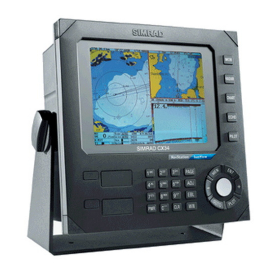
Installation 1 - 3 1.2 Installation of CX34 The unit can be flat or bracket mounted - overhead, bulkhead or console. 246 mm (9.7”) 220 mm (8.7”) SIMRAD 212 mm (8.3”) 33 (1.3”) 188 mm (7.4”) 112 mm (4.4”) Bulkhead mounting. - Page 10 Installation 1 - 4 CX34/44/54 NavStation Flush mounting of CX34 Removable corner for flush mounting. Minimum clearance incl. cables: 15 cm. Refer to included template for instructions on flush mounting. (measurements in mm)
-
Page 11: Installation Of Cx44
CX34/44/54 NavStation Installation 1 - 5 1.3 Installation of CX44 The unit can be flat or bracket mounted - overhead, bulkhead or console. 343 mm (13.5”) 42 (1.7”) 365 mm (14.4”) 75 mm (3.0”) 165 mm (6.5”) Overhead mounting. 75 mm (3.0”) Bulkhead mounting. - Page 12 Installation 1 - 6 CX34/44/54 NavStation Flush mounting of CX44 Removable corner for flush mounting. Minimum clearance incl. cables: 11 cm. Refer to included template for instructions on flush mounting. 337 mm (13.3”) 347 mm (13.7”) 353 mm (13.9”) 365 mm (14.4”)
-
Page 13: Installation Of Cx54
CX34/44/54 NavStation Installation 1 - 7 1.4 Installation of CX54 The unit can be flat or bracket mounted - bulkhead or console. Overhead and bulkhead mounting is only possible if using a distance piece. 42 (1.7”) 343 mm (13.5”) 460 mm (18.1”) 95 mm (3.7”) 75 mm (3.0”) 195 mm (7.7”) - Page 14 Installation 1 - 8 CX34/44/54 NavStation Flush mounting of CX54 Removable corner for flush mounting. Minimum clearance for cables: 13 cm. Refer to included template for instructions on flush mounting. 427.9 mm (16.8”) 437.9 mm (17.2”) 448 mm (17.6”) 460 mm (18.1”)
-
Page 15: Location For Display Unit
CX34/44/54 NavStation Installation 1 - 9 1.5 Location for display unit Determine which place is the most suitable and convenient for navigation and general operation after considering the following conditions: - you can see the ship’s bow when you raise or lower your eyes from the dis- play. -
Page 16: Operation Of Dual Station
Installation 1 - 10 CX34/44/54 NavStation The NMEA1 interface from the main unit CX44/54 is transferred to the dual station via the connection cable and is available on the dual station’s NMEA2 receptacle. Refer to section 1.8 for details on pin numbers. O-ring 153-3002-023 The connection cable between the dual station and the main unit is a special... -
Page 17: Connection Of Radar Supply Box Rs4050 Or Rs4052
CX34/44/54 NavStation Installation 1 - 11 1.7 Connection of Radar supply box RS4050 or RS4052 To run the radar scanners RB714/5/6/7/8A, an external power supply must be connected to the CX34/44/54. Be carefull to choose the correct supply box for the connected scanner. The RS4050 is for the 2kW and 4kW scanners. -
Page 18: Electrical Connections
Installation 1 - 12 CX34/44/54 NavStation 1.8 Electrical connections Page 1-12 and 1-13 are for CX34. (Page 1-14 and 1-15 are for CX44/54) - Page 19 CX34/44/54 NavStation Installation 1 - 13...
- Page 20 Installation 1 - 14 CX34/44/54 NavStation Electrical connections continued Page 1-14 and 1-15 are for CX44/54. (Page 1-12 and 1-13 are for CX34)
- Page 21 CX34/44/54 NavStation Installation 1 - 15...
-
Page 22: Power Supply Connections
CX34: Recommended transducers Airmar single element two-frequency 50/200 kHz transducers i.e. B744V, P319, B45, B256, P66 and P52. CX44/54: Recommended connection and setup (refer to Operator manual) of Simrad supplied transducers Transducer type Port Echosounder setup Simrad C38/200 ECHO2 Simrad Combi 38&200... - Page 23 CX34/44/54 NavStation Installation 1 - 17 CX44/54: Transducer connections: Internal connections Transceiver Transceiver 50/200kHz 38/200kHz ECHO1 ECHO2 Combi transducer 38 and 200, or 50 and 200kHz Single frequency Single frequency 50 or 200kHz 38 or 200kHz Two frequency 50/200kHz ! Warning! Transducers containing speed log sensor e.g.
-
Page 24: Interface Connection
The 34, 44 and 54 series feature three possibilities for interconnection and data sharing: SimNet, which is recommended for control and data sharing between Simrad SimNet products. NMEA2000, SimNet products will interface and share data with NMEA2000 based products. NMEA0183, which has been the common standard for marine elec- tronics. - Page 25 CX34/44/54 NavStation Installation 1 - 19 SimNet power and termination The following simple rules should be observed when installing SimNet: • SimNet must be powered with 12 VDC and connected to the battery via circuit breaker and 5 amp fuse. •...
-
Page 26: Pc Up/Download Via Nmea Connection
Installation 1 - 20 CX34/44/54 NavStation SimNet / NMEA2000 network, medium system CX33 CX44 Tee Joiner AT44 Active Tee 12V supply * The supply cable and wind transducer have a built-in terminator. 1.8.5 PC up/download via NMEA connection A PC can be connected to CX34 via the NMEA port, or to CX44/54 via the NMEA2 port, to enable exchange of waypoint and route data. -
Page 27: Installation Of Gps/Dgps Antenna
CX34/44/54 NavStation Installation 1 - 21 1.9 Installation of GPS / DGPS antenna The antenna must be placed in a position where tall constructions, steel wires, masts, etc. do not obstruct the view to the satellites. Do not, however, mount the antenna in the top of a mast or tower, as this may degrade the COG and SOG readings, especially if DGPS is used. -
Page 28: Optional Connections
Installation 1 - 22 CX34/44/54 NavStation 1.10 Optional connections SIMRAD -Compass -WR20 RemoteCommander -Dual Station DS34/44/54-CX -Performance Instruments -Differential Beacon Receiver -Water speed and temperature sensor -Autopilot -Yeoman digitizer -PC - WPs & routes up/download -Other equipment via SimNet, NMEA0183, or NMEA2000. -
Page 29: Basic Transducer And Cable Information
Only applicable for CX44/54 models: The CX44/54’s transmitter is designed to match Simrad 1kW 75 ohms high performance transducers described in section 1.12.1 Transducers. However, when using a 600 W single element transducer e.g. B744V, the 1kW... -
Page 30: Transducers
CX34/44/54 NavStation 1.12.1 Transducers Simrad Combi-transducers C50/200 or C38/200 For optimum performance of the CX44/54 echosounder function, the Simrad combi transducers C38/200 and C50/200 are recommended. These transduc- ers also include a water temperature sensor. A variety of alternative medium- range transducers is available for vessels mainly operating in shallow waters and/or where the size of the transducer is critical. - Page 31 CX34/44/54 NavStation Installation 1 - 25 Airmar P319 Thru-hull mount Frequency: 50/200 kHz Beamwidth: 45° / 15° Cable length: 10m (32’) Depth information. Reference no. 179-0401-002 (P319) Housing: Reinforced plastic Recommended for fiberglass and metal hulls. Do not use in wooden hulls! Reference no.
- Page 32 Installation 1 - 26 CX34/44/54 NavStation Airmar SS505 Ref.no. 179-0401-011 Optional fairing Thru-hul stem mount Accomodates hull thickness: Min. no fairing 6 mm (1/4”), Max. with fairing 83 mm (3 1/4”) Frequency: 50/200 kHz Beamwidth: 45° / 15° Cable length: 10m (32’) Depth information.
-
Page 33: Determining The Position For The Transducer
CX34/44/54 NavStation Installation 1 - 27 Airmar B744V Thru-hull triducer Frequency: 50/200 kHz Beamwidth: 45° / 15° Cable length: 10m (32’) Speed, temperature + depth information. Ref.no. 179-0401-009 (B744V) Housing: Bronze Recommended for fiberglass and wooden hulls. Do not connect to CX44/54’s ECHO2 port. - Page 34 Installation 1 - 28 CX34/44/54 NavStation can be great variation in the amount of air bubbles which are carried beneath the hull. These bubbles tend to be carried close to the hull as they pass aft. For this reason, it is desirable for the transducer to be mounted on a fairing block which holds the transducer away from the hull and which directs the flow of aerated water around the sides of the transducer rather than over the face of the transducer.
-
Page 35: Installation Of Scanner
CX34/44/54-series Installation 1-29 1.13 Installation of scanner This illustration is a typical radar system: Radar scanner Display unit GPS antenna Compass 12/24 Volt supply AT44 12 Volt supply SimNet How to determine the site of installation A radar’s target detection capacity varies greatly depending on the fitted posi- tion of the scanner. -
Page 36: Shifting Away From Obstacles
Installation 1-30 CX34/44/54-series 1.13.1 Shifting away from obstacles Shifting from keel line: By shifting the scanner position from the keel line to the starboard side of the ship, it is possible to move shadow zones to the port side which makes it possible to keep a clear vision in the bow direction. The distance to be shifted can be obtained by calculation depending on the dis- tance from the scanner to obstacles using the following equation: Ls=0.4R+D/2 [m]... -
Page 37: Mounting Of Scanner
CX34/44/54-series Installation 1-31 1.13.2 Mounting of scanner Deciding the place of installation, a minimum distance must be considered to the master compass (2 meters) and steering compass (1.4 meters). If a mount base like the one shown below is available, it may be easier to install the scanner. - Page 38 Installation 1-32 CX34/44/54-series DX45 Radome scanner 465 mm (18.3”) • 46.5 cm radome • 4 kW • Range up to 28 nm 261 mm • Rotation speed 20-50 rpm (10.3”) • Beamwidth: Horizontal 5.6° Vertical 30° Forward The four bolts included with your radar equipment will suffice for mount base thickness of 9 to 14 mm (0.35 to 0.55 in.).
- Page 39 CX34/44/54-series Installation 1-33 DX60 Radome scanner 615 mm (24.2”) • 61.5 cm radome • 4 kW • Range up to 36 nm 261 mm • Rotation speed 20-50 rpm (10.3”) • Beamwidth: Horizontal 3.8° Vertical 30° Pads for support of radome scanner DX60: If the DX60 is to be mounted on a flat surface, the four pads (included) for support are to be placed according to this illustration.
- Page 40 Installation 1-34 CX34/44/54-series RB714A Radome scanner 448 mm (17.9”) • 45 cm radome • 2 kW 220 mm • Range up to 24 nm (8.8”) • Rotation speed 24 rpm • Beamwidth: Horizontal 5.9° Vertical 25° Chassis Radome (bottom) Mounting base Washer Spring washer Included...
- Page 41 CX34/44/54-series Installation 1-35 RB715A Radome scanner 660 mm (26.4”) • 65 cm radome • 4 kW 255 mm • Range up to 36 nm (10.2”) • Rotation speed 24 or 48 rpm • Beamwidth: Horizontal 3.9° Vertical 25° Chassis Radome (bottom) Mounting base Washer Spring washer...
- Page 42 Installation 1-36 CX34/44/54-series RB716A Open scanner • 3 or 4ft Open array 4’ 1346mm (53.8”) 330mm • 4 kW 3’ 1034mm (41.4”) (13.2”) • Range up to 48 nm • Rotation speed 24 or 48 (24V) rpm 450mm • Beamwidth: (18”) Horizontal 2.5°, 1.8°...
-
Page 43: Connecting Cables
CX34/44/54-series Installation 1-37 Drilling template for RB716A, RB717A, RB718A. The bolts included with your radar equipment will suffice for mount base thickness of 9 to 14 mm (0.35 to 0.55 in.). If the mount base is thicker or thinner than this, prepare bolts as listed on page 1-31. - Page 44 Installation 1-38 CX34/44/54-series Interconnecting cable (DX45 + DX60) 1. Run the cable and fasten it at intervals of about 40 cm. 2. Remove the upper part of the radome from the scanner (loosen 4 screws with incl. Allen key). Avoid bumping it against the antenna by lifting it vertically.
- Page 45 CX34/44/54-series Installation 1-39 Interconnecting cable (DX45 + DX60) - continued Fig.1 Fig.2 Logo seal on side wall Fig.3 Ship’s heading Cable inlet Tighten the four screws to 1.5 Nm (max)
- Page 46 Installation 1-40 CX34/44/54-series Interconnecting cable (RB714A + RB715A) 1. Run the cable, and fasten it at intervals of about 40 cm. 2. Remove the upper part of the radome from the scanner (loosen 4 screws). Avoid bumping it against the antenna by lifting it vertically. 3.
- Page 47 CX34/44/54-series Installation 1-41 Fitting interconnection cable (RB714A): Antenna Stern side Shield cover Cable shield Fixing plate Fix connector on X1 Radome Rubber ring (bottom) Interconnection cable Inner shield X1 (Connect here) Radome (bottom)
- Page 48 Installation 1-42 CX34/44/54-series Fitting interconnection cable (RB715A): Antenna Stern side Shield cover Cable shield Fix connector on Fixing plate Radome PCB X11, X12 (bottom) Rubber ring Interconnection cable Inner shield X11 (Connect here) X12 (Connect here) Radome (bottom)
- Page 49 CX34/44/54-series Installation 1-43 Interconnecting cable (Open Scanner) 1. Run the cable, and fasten it at intervals of about 40 cm. 2. Use a T-wrench to remove the back covers of the scanner unit. 3. Remove the two bolts securing the transceiver and pull out the transceiver after removing two connectors: to Motor (X1) and to Heading switch (X2).
- Page 50 Installation 1-44 CX34/44/54-series Fitting interconnection cable (Open scanner): TR unit fixing bolts Remove connector Fixing bolt Clumper Fixing plate Interconnection cable Fixing bolt Cable shield terminal 10 mm Washer Fixing plate Scanner unit Rubber Interconnection cable Cable inlet...
-
Page 51: Connector's Pin Numbers And Wire Colors
CX34/44/54-series Installation 1-45 1.13.4 Connector’s pin numbers and wire colors The connecting cable is supplied with the radar scanner. The 18-pin round connector is connected to the main unit’s receptacle marked RADAR: (seen from solder side) – refer to section 1.8 for details on pin numbers. The connector at the other end of the connecting cable is for the radar scanner, and consist of the following pin numbers and wire colors: Wire colors and pin numbers for the DX45 and DX60 Radar scanner... - Page 52 Installation 1-46 CX34/44/54-series Connector for the RB714A Radar scanner Connector for the RB715A Radar scanner...
- Page 53 CX34/44/54-series Installation 1-47 Connector for the Open Scanners (RB716A, RB717A, and RB718A)
-
Page 54: Grounding Wire
Installation 1-48 CX34/44/54-series 1.13.5 Grounding wire Connect a grounding wire from one of the bolts on the scanner base, as shown below. The crimp terminal and grounding wire are installer-supplied. Chassis Radome Radome (bottom) Mount base To ship’s hull Crimp terminal Grounding wire Open scanner Terminal... -
Page 55: Specifications
CX34/44/54-series Installation 1-49 1.14 Specifications of the CX34, 44 & 54 General data Power supply: 12 and 24 V DC (10-32 V DC max) 20-70 watt (+ Radar supply box - see next page) Power cable: 2 m, 4 pin female connector, (153-5000-007), inclusive: - power fuse T6.3A slow (5x20mm) - fuse for DX radar scanners F8.0A fast (5x20mm) CSD:... - Page 56 Installation 1-50 CX34/44/54-series Radar supply box RS4050 to run radar scanners RB714/5/6A Addendum: 183-0700-003 Dimensions: H:125 mm, L:222 mm, D:81 mm Power supply: 12 and 24 V DC (10-32 V DC max) Fuses: Radar supply fuse 4A F Main fuse 6A.3F High voltage fuse 160 mAF Radar motor fuse 6A.3F Radar supply box RS4052 to run radar scanners RB717/8A...
- Page 57 CX34/44/54-series Installation 1-51 Chartplotter section Chart system: C-MAP MAX or NT+ Presentation: Dual chart - two charts in individual scales and detail levels Internal memory: Dynamic storage with combinations of/or totals up to: 35,000 marks/waypoints 10,000 waypoints with name (25 characters) 50,000 trackpoints 50,000 line sections 1,000 routes...
- Page 58 Installation 1-52 CX34/44/54-series Antenna: Slotted waveguide array, horizontal polarization, rotation rate 20-50 rpm. - beam width: DX45 = 5.6° horizontal, 30° vertical. DX60 = 3.8° horizontal, 30° vertical. Housing: Casted aluminum and ASA. Cables: 153.3003.100 153.3003.150 153.3003.200 153.3003.300 153.3003.400 Radar radome scanners RB714A RB715A Radome:...
- Page 59 1500 m 200 kHz 7° 280 m 400 m *Single Fish Target Strength: -30dB (60 cm cod) *Bottom Back Scattering Strength: -20 dB *Simrad transducer 38/200 or 50/200 Pulse length: Short, medium, long and auto Transmission rate: 10 pings per second...
- Page 60 600 W plastic thru-hull transducer, 45° and 15° beam. ST850: Speed and temperature only. Dual frequency transducers (CX44/54) Simrad 38&200, 1 kW high performance combi transducer 38 and 200 kHz, 13x21° and 7° beams. Simrad 50&200, 1 kW high performance combi transducer 50 and 200 kHz, 10x16°...
- Page 61 2 m (6.6’) SimNet power excl. termination (24005910) AT10 Universal NMEA0183 converter (24005936) SimNet cable protection cap (24005928) SimNet/NMEA2000 drop cable (24005729) Options for CX34/44/54 Simrad DataCards C-MAP electronic charts NT+ and MAX WR20 RemoteCommander 6-channel NMEA Buffer RS5345 PC data cable, 1.5 m (153-3002-024)
- Page 62 Installation 1-56 CX34/44/54-series...
Need help?
Do you have a question about the CX34-DE NavStation and is the answer not in the manual?
Questions and answers