Simrad AP70 Installation Manual
Hide thumbs
Also See for AP70:
- Operator's manual (72 pages) ,
- Operation manual (66 pages) ,
- Quick start manual (7 pages)
Table of Contents
Advertisement
Advertisement
Table of Contents

Related Manuals for Simrad AP70


Summary of Contents for Simrad AP70
- Page 1 AP70/AP80 Installation Manual ENGLISH navico.com/commercial...
- Page 3 The AP70 and AP80 systems complies with the following regulations: • Wheelmark directive 2002/84 EC (HCS and HSC) • CE (2004-108 EC EMC Directive) - AP70 systems when used with an AC70 computer • C - Tick ¼ Note: AP70 systems are not wheelmark approved when used with an AC70 computer.
- Page 4 In case of any queries, refer to the our websites: www.navico.com/commercial and www.simrad-yachting.com. About this manual This manual is a reference guide for installing and commissioning the Simrad AP70 and AP80 Autopilot Systems. The manual will be continuously updated to match new sw releases. The latest available manual version can be downloaded from our web sites.
-
Page 5: Table Of Contents
System overview Autopilot Control units Autopilot computers Computer boards Mounting General Mounting location AP70 and AP80 control units Autopilot computers Wiring Wiring guidelines The autopilot system, basic wiring principles The CAN bus Power supply FU80, NF80 and QS80 Remote control units... - Page 6 Installation checklist General Checklist Installation settings Installed unitsw Specifications AP70 and AP80 Autopilot system AP70 and AP80 Control units Autopilot Computers Computer boards AP70 and AP80 Connector pinouts Supported data Drawings AP70 Control unit AP80 Control unit AC70 and SI80 Computer...
-
Page 7: Introduction
Spare parts and accessories List of spare parts and accessories for the AP70/AP80 system can be found on our websites. System overview The AP70/AP80 systems include several modules that need to be mounted in different... - Page 8 AP70, simple system example HS70 AP70 CONTROL UNIT QS80 MENU TURN STBY AUTO WORK 12/24V DC RC42N AC70 12 V DC NMEA 0183 IN/OUT TERMINATOR CAN BUS DROP CABLES NMEA 0183/ IEC 61162-1/ IEC 61162-2 12/24V DC DRIVE UNIT...
- Page 9 AP80 CONTROL UNIT GS15 MENU TURN CDI80 STBY AUTO WORK CD100A 12/24V DC IS70/80 GYRO COMPASS AC80S AD80/ SD80 TERMINATOR CAN BUS DROP CABLES NMEA 0183/ IEC 61162-1/ IEC 61162-2 12/24V DC SOLENOID THRUSTER VALVES CONTROL Introduction | AP70/AP80 Installation Manual...
- Page 10 TURN STBY AUTO WORK CD100A 12/24V DC GYRO ECDIS SYSTEM COMPASS AD80/ AD80/ TERMINATOR SD80 SD80 AC85 CAN BUS DROP CABLES NMEA 0183/ IEC 61162-1/ IEC 61162-2 12/24V DC RUDDER THRUSTER CONTROL CONTROL 10 | Introduction | AP70/AP80 Installation Manual...
-
Page 11: Autopilot Control Units
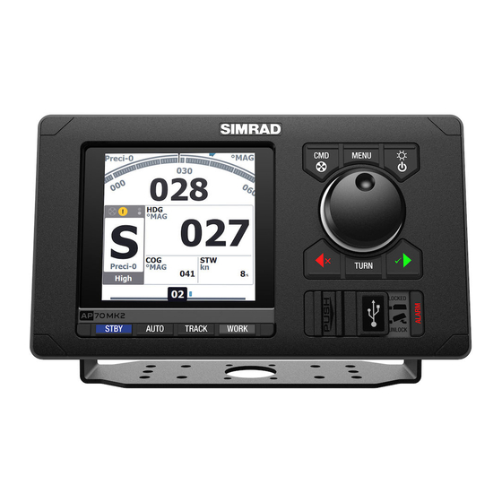
STBY. Turns the autopilot to Standby mode AUTO. Activates Auto NoDrift mode NAV (AP70) / TRACK (AP80). Activates Track steering mode WORK. Used for selecting work profile USB port door ALARM. Displays the Alarm listing dialog AP80 control units only... -
Page 12: Autopilot Computers
Ethernet network port, used for sw update Autopilot computers SD80 The AP70/AP80 systems use a combination of 5 different enclosures and 4 boards to form a AD80 flexible computer and interface system. There are 7 standardized and 1 customized computers with built-in and optional boards as AC70 shown below. - Page 13 The AC85 computer is supplied with 1 SI80 board, and have space for up to 3 additional boards: Computer AC70 board AD80 board SD80 board SI80 board AC85 Optional Optional Optional 1 Optional | 13 Introduction | AP70/AP80 Installation Manual...
-
Page 14: Computer Boards
REMOTE - Input for NFU steering lever • MODE - Input for external mode selector • SIMNET - connection to CAN network 30 A FUSE ALARM MODE RUDDER SIMNET DRIVE ENGAGE SUPPLY DRIVE NMEA0183 REMOTE SCREEN TERMINATION 14 | Introduction | AP70/AP80 Installation Manual... - Page 15 HS2 - Generic in/out handshake signal port 2 • MODE - Input for external mode selector • SIMNET - connection to CAN network U IN RANGE READY SIMNET SOLENOIDS RUD FREQ ENGAGE RUD UI SCREEN TERMINATION MODE | 15 Introduction | AP70/AP80 Installation Manual...
- Page 16 NMEA 0183 CH.. - 4 i/o NMEA/IEC 61162-1/IEC 61162-2 channels • SUPPLY - power supply 12/24 V in AC85 AC85 FUSE SIMNET TERMINATION SIMNET NMEA 0183 NMEA 0183 SUPPLY REMOTE NMEA 0183 NMEA 0183 16 | Introduction | AP70/AP80 Installation Manual...
-
Page 17: General
Ensure you have as much separation as possible between different electrical equipment. AP70 and AP80 control units Avoid mounting a control unit where it is easily exposed to sunlight, as this will shorten the lifetime of the display. - Page 18 Connect the cables to the rear of the unit before placing the unit into the console Secure the display to the surface with 4 screws (B) Firmly clip the bezel in place (C) ¼ Note: For AP80 the bezel may not be used for flush/low profile installations. 18 | Mounting | AP70/AP80 Installation Manual...
- Page 19 Secure the bracket’s adapter to the rear of the control unit using the 4 screws supplied with the bracket Align the bracket base with the cradle and partially screw in the bracket knobs one at a time Adjust the unit for best viewing angle, and tighten the bracket knobs | 19 Mounting | AP70/AP80 Installation Manual...
-
Page 20: Autopilot Computers
For Micro-C based networks use the SimNet to Micro-C (male) converter cable p/n 24005729. AC70/SI80 AC80A/AC80S SD80/AD80 AC85 SG05 PRO ¼ Note: The autopilot computers are not waterproof. Refer “Specifications” on page 70. 20 | Mounting | AP70/AP80 Installation Manual... -
Page 21: Wiring
The autopilot system, basic wiring principles The AP70 and AP80 autopilot system use a CAN bus backbone which makes it simple to interface to SimNet and NMEA 2000 devices. NMEA 0183 devices, rudder feedbacks and other control devices connects to an autopilot computer. - Page 22 CAN bus Drop cable, connectors in each end (female - male) CAN bus Backbone, various lengths available. Connectors in each end Terminator, 120 ohm, male ¼ Note: If cables are not supplied by Simrad, ensure that they meet NMEA 2000/IEC61162-1/2 requirements. Planning and installing a network backbone •...
-
Page 23: Power Supply
For larger systems additional power should be added at a central point in the backbone to balance the voltage drop of the network. Additional power should be supplied by using an SI80 board. Refer “Network LEN” on page 24. | 23 Wiring | AP70/AP80 Installation Manual... - Page 24 Switch off the power supply voltage and put the fuse into correct position The illustration shows power terminal and diodes on the AC70 board. For location of terminals, fuse and diodes on the board, refer to the illustration inside the computer unit. SUPPLY 24 | Wiring | AP70/AP80 Installation Manual...
-
Page 25: Fu80, Nf80 And Qs80 Remote Control Units
Powering the AP70 and AP80 control units The AP70 and AP80 control units are powered directly from a 12 V DC or 24 V DC source. The units are protected against reverse polarity, under voltage and over voltage. Power cable connector (female) -
Page 26: Nmea 2000 And Simnet Devices
CAN bus backbone using drop cables and Micro-C T-joiners. ¼ Note: It is recommended to use a gateway when connecting non-Simrad units to the CAN bus backbone. Devices with SimNet connectors only must be connected using a SimNet to Micro-C adapter cable. -
Page 27: Autopilot Computers
CAN bus back bone. The drop cable is connected to the male connector on the Micro-C T-joiner, and to the SimNet terminal on the computer board. The drop cable is supplied with the autopilot computer. | 27 Wiring | AP70/AP80 Installation Manual... -
Page 28: Drive Units
Installation instructions for the drive units are found in the manuals for the individual units. Reversible pump Connects to: AC70 board (in AC70 or AC85 Computer). REVERSIBLE PUMP AC70 BOARD DRIVE AC70 or AC85 Computer MOTOR 28 | Wiring | AP70/AP80 Installation Manual... - Page 29 For solenoids with higher voltage (110/220 V AC or DC), use external relays/solid state relays. Internally powered Solenoids Connects to: AC70 board (in AC70 or AC85 Computer). SOLENOID VALVE AC70 BOARD DRIVE AC70 or AC85 Computer | 29 Wiring | AP70/AP80 Installation Manual...
- Page 30 Connects to: AC80 board (in AD80, AC80A or AC85 Computer). The AD80 board provides analog control of rudder(s) and thrusters in an AP70 and AP80 system by either continuous voltage or current signal. The UI_CTRL DIP switch is used to voltage control line.
- Page 31 READY For Analog output, external voltage, the switch must be set to EXT. STEERING GEAR AD80 BOARD U_CTRL READY AD80, AC80A or AC85 SIGNAL UI_CTRL Computer 12-24 V DC EXTERNAL STEERING GEAR SUPPLY | 31 Wiring | AP70/AP80 Installation Manual...
- Page 32 51. U_CTRL READY For Analog output, current, the switch must be set to INT. STEERING GEAR AD80 BOARD U_CTRL READY AD80, AC80A or AC85 4-20 mA UI_CTRL Computer 32 | Wiring | AP70/AP80 Installation Manual...
-
Page 33: Rudder Feedback
The grounding wire should be as short as possible and at least 10 mm wide. AD80/SD80 BOARD RUD_FRQ + - x RF14XU AD80/SD80, 5 6 7 AC80S or AC85 Computer | 33 Wiring | AP70/AP80 Installation Manual... - Page 34 EXTERNAL VOLTAGE INPUT AD80/SD80, AC80S or AC85 External Computer I_IN feedback U_IN U_IN signal RUD_UI U_IN RANGE +20V +10V The DIP switch must be set to match range for analog voltage input signal. 34 | Wiring | AP70/AP80 Installation Manual...
-
Page 35: Alarm Interface
External alarm setup The siren must be enabled in order for the unit to drive the external alarm when an alarm condition arises. Refer the alarm description in the separate AP70/AP80 Operator manual. External Take command An external take command signal... -
Page 36: External I/O
Central alarm panel with direct I/O interface Connects to: AP70/AP80 Control unit, and AD80 board or SD80 board. The interfacing described below applies for central alarm panels that use direct lines for alarm, mute and acknowledge. For alarm panel using serial interface, refer to “IEC61162-1/2 (NMEA 0183) devices”... - Page 37 For SD80 the drive voltage is galvanic isolated and has to be externally supplied. The output can also be sw configured for proportional valve control. AC70 BOARD AC70 or AC85 Supply Computer ENGAGE | 37 Wiring | AP70/AP80 Installation Manual...
- Page 38 Some steering gears will use the signal to block rudder/thruster command in case of a serious autopilot failure. AD80/SD80 BOARD AD80/SD80, AC80S or AC85 OUT A OUT A Computer OUT B OUT B 100 mA READY 38 | Wiring | AP70/AP80 Installation Manual...
-
Page 39: External System Selection
External mode selection can be arranged with push buttons as shown in the figure below. STBY AUTO The two push buttons will have similar function as the keys on the AP70 and AP80 control units. PART OF AD80/SD80 BOARD EXTERNAL... -
Page 40: Ecdis System
The backup navigator alarm can only be acknowledged from AP80. To enable this feature, the autopilot system provides a configurable handshake port on SD80 or AD80 that can be connected to an external alarm panel or loudspeaker. 40 | Wiring | AP70/AP80 Installation Manual... -
Page 41: System Configuration
On additional control heads, acknowledge language selection and cancel all other setup requests. If the settings are not completed, you can configure the autopilot system manually as described in the following sections. | 41 System configuration | AP70/AP80 Installation Manual... -
Page 42: Network Settings
The autopilot system can use data sources that all other products on the network use, or select individual sources for the autopilot system. If the group is set to Simrad, any changes to a source will also affect other systems on the network. -
Page 43: Device List
255 is reached. Check same things as for Bus state if Tx Errors greater than 0 observed Detected errors since power up. Check the network if this is continually Fast packet Errors: increasing. | 43 System configuration | AP70/AP80 Installation Manual... - Page 44 To fulfill this requirement the AP70/AP80 system includes a Master function. This is used in larger Wheelmarked systems where you permanently want to control command transfer to remote stations.
- Page 45 In the illustration below the main bridge is defined as master station. One QS80, one AP80 control unit and one AP70 control unit are included in the master station. The AP80 control unit is defined as the Master unit.
-
Page 46: Installation Settings
The figure shows a completed commissioning for a vessel with one rudder driven by an SD80 board, one solenoid operated tunnel thruster and one analog tunnel thruster operated by two different AD80 boards. 46 | System configuration | AP70/AP80 Installation Manual... - Page 47 AD80 AD80 Select the Configure option to proceed to device configuration dialog. The dialog differs slightly for the different drive types Select relevant settings for the selected drive, and save your settings | 47 System configuration | AP70/AP80 Installation Manual...
- Page 48 It is recommended to check rudder stability in AUTO mode at cruising speed to get pressure on the rudder. (Slight hunting observed dockside may disappear at cruising speed.) Range: 0,1 – 4 (default: 0,5) 48 | System configuration | AP70/AP80 Installation Manual...
- Page 49 “External” and use the installed current or voltage input to the RUD UI plug of SD80/AD80 board for follow up rudder control. ¼ Note: Must be limited to one autopilot computer board | 49 System configuration | AP70/AP80 Installation Manual...
- Page 50 The pendulum feature is intended for pendulum ferries where it is required to turn the heading 180° when the vessel is going «backwards». The feature can be included in AP70/80 systems equipped with SD80 or AD80 boards. It can only be used for NMEA 0183 heading sensors, RC42 and CDI80.
- Page 51 The graphics below shows the dialog when the rudder is controlled by an SD80. The configuration dialog varies with drive device and drive type. Select feedback calibration option in the device configuration dialog Follow the guided steps through the calibration process Save the settings when completed | 51 System configuration | AP70/AP80 Installation Manual...
-
Page 52: Vessel Configuration
On power boats it is recommended that you set a value that represents the speed where the hull begins to plane or the speed where you change from slow to cruising speed. 52 | System configuration | AP70/AP80 Installation Manual... - Page 53 Midships moves the rudder to zero position. Actual maintains the rudder offset, and use this as trim value (bumpless transfer) ¼ Note: Actual is only available with rudder feedback signal available. • Default: Midships | 53 System configuration | AP70/AP80 Installation Manual...
-
Page 54: Seatrials
¼ Note: Calibration must be made on the compass that is active for the autopilot. If another model compass from Simrad or another manufacturer is installed, refer to the calibration instruction for that compass. ¼ Note: In certain areas and at high latitudes the local magnetic interference becomes more significant and heading errors exceeding ±3°... -
Page 55: Tuning The Autopilot For Optimum Steering Performance
Stabilize the vessel on a heading, and then select mode Observe course keeping and rudder commands The autopilot should keep the vessel on the set heading within an average of +/-1 degree, providing calm sea and wind | 55 System configuration | AP70/AP80 Installation Manual... - Page 56 The settings depends on vessel’s characteristics, loaded/ballast conditions and rate of turn. • If the vessel has good dynamic stability, relatively small settings will be sufficient • An unstable vessel will require high settings 56 | System configuration | AP70/AP80 Installation Manual...
- Page 57 Counter rudder that gives a little overshoot to one side and a bit sluggish response to the other. • Range: 0.05 - 32.00 • Default: Defined by system based on boat type and length | 57 System configuration | AP70/AP80 Installation Manual...
-
Page 58: The Alarm System
The alarm system The AP70/AP80 system will continuously check for dangerous situations and system faults while the system is running. Message types There are two type of messages: • Alarms Generated when conditions are detected that critically effect the capability or performance of the system. -
Page 59: Acknowledging A Message
List of all active messages • Alarm history Alarm events, including alarm type and time/date • Alarm settings List of all alarms that can be enabled and configured by the user | 59 The alarm system | AP70/AP80 Installation Manual... -
Page 60: Setting The Alarm And Warning Limits
Rudder is kept at fixed angle (i.e. heading is approximately maintained if failing when heading keeping, turn is approximately maintained if failing when turning), alarm is given and STBY autopilot goes to mode. 60 | The alarm system | AP70/AP80 Installation Manual... -
Page 61: List Of Possible Alarms And Corrective Actions
List of possible alarms and corrective actions The next pages includes a list of all alarms generated by the autopilot system. The AP70/AP80 control units might also display alarms received from other units connected to the system. Refer separate documentation for the relevant equipment for further descriptions of these alarms. - Page 62 Alarm/Warning Type Warning/Alarm condition Possible cause and recommended action Local supply voltage to AP70/AP80 missing or <5 V. Red flashing AP70/ AP80 power button, < 5 V Check local supply, connections and fuses to AP70/AP80 black display control units Active control unit goes silent.
- Page 63 Low boat speed steering in Work profile profile). Switch to hand steering or adjust Work profile settings. Monitor compass Lost sensor data No data from the selected monitor compass. (Warning only.) missing | 63 The alarm system | AP70/AP80 Installation Manual...
- Page 64 If unintended warning, check that the boat speed to the Acceleration > set g-limit Sharp turn autopilot is correct. Check that set turn rate or radius (Alarms - settings) corresponds to actual 64 | The alarm system | AP70/AP80 Installation Manual...
- Page 65 Thruster inhibited Vessel speed > set limit ¼ Note: The Thruster inhibit limit will only apply when speed source is Log or SOG, not if the speed is set manually. | 65 The alarm system | AP70/AP80 Installation Manual...
-
Page 66: Installation Checklist
52 Compass calibrated page 54 Seatrial completed (Autotune) page 56 Seatrial completed (Manual tuning) page 56 Connected equipment approved according to notified body User training provided Date: Signature Installer Signature Captain 66 | Installation checklist | AP70/AP80 Installation manual... -
Page 67: Installation Settings
Rudder zero Zero output Min output Max output Remote FU/DP Remote FU/DP calibrate Boat Setting Dockside boat Boat type Boat length Cruising speed Transition speed Thruster inhibit speed Low speed limit Init rudder | 67 Installation checklist | AP70/AP80 Installation manual... - Page 68 Low speed limit Track steering Track response Track approach angle Course change limits XTD limit Drive select Rudder Init rudder Rudder limit Tow angle Thruster Thruster sensitivity Thruster assist Push boat to Port Starboard 68 | Installation checklist | AP70/AP80 Installation manual...
-
Page 69: Installed Unitsw
Installed unitsw Unit Type Location Date Control units Remotes Computers Feedbacks Compass Other units | 69 Installation checklist | AP70/AP80 Installation manual... -
Page 70: Specifications
Specifications AP70 and AP80 Autopilot system ¼ Note: For updated technical specifications, compliance and certifications, refer to our websites. Power (displacement, outboard and planing). From Boat type: 30 ft and up Hydraulic; Reversible pump/Solenoids Steering system types: Mechanical; Rotary drive/Linear drive. -
Page 71: Ap70 And Ap80 Control Units
AP70 and AP80 Control units AP70 AP80 DISPLAY Size 5 in\127 mm Resolution (HxW) 480x480 Type 16-bit color TFT Antifog bonded Best viewing direction any direction Backlight Cold Cathode Fluorescent Lamp (CCFL) NETWORKING CAN bus Ethernet for sw update POWER... -
Page 72: Autopilot Computers
Bulkhead Compass safe distance Plastic front and anodized Material Plastic aluminum back Color Black Slots: Cable inlet 9 x 95 mm and 18 x 45 mm (0.4” x 3.7” and 0.7” x 1.8”) 72 | Specifications | AP70/AP80 Installation manual... - Page 73 7 - 10 mm (0.3” - 0.4”) 10 - 14 mm (0.4” - 0.6”) 4 for cable diameter 7 for cable diameter 10 - 14 mm (0.4” - 0.6”) 14 -20 mm (0.6” - 0.8”) | 73 Specifications | AP70/AP80 Installation manual...
-
Page 74: Computer Boards
"Supply range: 5-24 V DC Control range: Analog voltage 5-95% of control of rudder/ supply range thruster, external with zero ref at supply min or half ref. voltage, max load 5 mA" 74 | Specifications | AP70/AP80 Installation manual... - Page 75 SYSTEM SEL, STBY, SYSTEM SELECT, Mode input AUTO, TRACK, common ret, close common ret, to activate, contact current max close to activate, 30 mA contact current max 30 mA | 75 Specifications | AP70/AP80 Installation manual...
- Page 76 Mains steering wheel override, remote FU/ DP request) Max 100 mA, External alarm output voltage level as for buzzer/relay local supply EVC (Electronic Vessel CAN via SG05 CAN via SG05 Gateway Control) interface Gateway 76 | Specifications | AP70/AP80 Installation manual...
-
Page 77: Ap70 And Ap80 Connector Pinouts
Function (Bare) Shield NET S (+12 V) Black NET C (-) White NET H Blue NET L Ethernet ¼ Note: Both straight and crossed Ethernet cable may be used for software upload (AP70)! | 77 Specifications | AP70/AP80 Installation manual... -
Page 78: Supported Data
* When magnetic heading source 127250 * When true heading source 127237 127237 129025, 129026, 127258 129283, 129284 127258,129025, 129026,129033 127251 127245 127250 TNT* 130862 * Proprietary track control 128259 127250, 128259 129026 129026 129033 78 | Specifications | AP70/AP80 Installation manual... -
Page 79: Drawings
Drawings AP70 Control unit 54 mm (2.13”) 65 mm (2.56”) 135 mm (5.31”) 32 mm (1.26”) 144 mm (5.67”) 220 mm 230 mm (8.66”) (9.06”) | 79 Drawings | AP70/AP80 Installation manual... -
Page 80: Ap80 Control Unit
AP80 Control unit 54 mm (2.13”) 65 mm (2.56”) 135 mm (5.31”) 32 mm (1.26”) 144 mm (5.67”) 220 mm 252 mm (8.66”) (9.92”) 80 | Drawings | AP70/AP80 Installation manual... -
Page 81: Ac70 And Si80 Computer
180 mm (7.08") 80 mm (3.15") 48 mm (1.88") SD80 and AD80 Computers 211 mm (8.29") 197 mm (7.77") 185 mm (7.27") 60 mm (2.36") 167 mm (6.58") 80 mm (3.15") 48 mm (1.88") | 81 Drawings | AP70/AP80 Installation manual... -
Page 82: Ac80A And Ac80S Computer
(4.29”) 250 mm (9.94”) AC85 Computer 408 mm (16.06") 5 mm (0.20") 380mm (14.96") 290 mm (11.42") 440 mm (17.32") 410 mm (16.14") 373 mm (14.69") 4 fixing holes, (0.3") 106 mm (4.17") 82 | Drawings | AP70/AP80 Installation manual...
Need help?
Do you have a question about the AP70 and is the answer not in the manual?
Questions and answers