Table of Contents
Advertisement
Quick Links
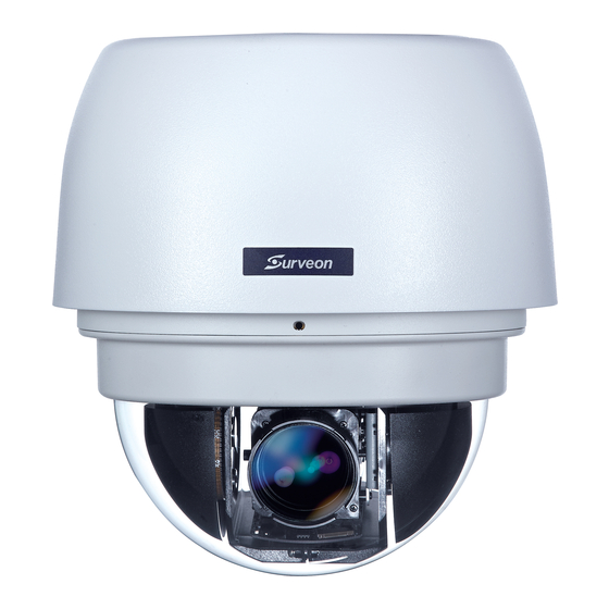
Full HD Outdoor Speed Dome
Hardware Installation
Warning!
Only qualified service personnel should install and service this product in order to avoid risk of injury from
electrical shock and energy hazard.
Observe all ESD (Electro-static Discharge) procedures during installation to avoid damage to the camera and its
components.
Tools Required
Philips Screwdriver
User-provided Items:
●
●
●
Mini Screwdriver
PC with Windows (XP or above) and web browsers (Internet Explorer
●
Electrical Drill
●
6.0 or above) installed.
Wrench Kit
●
Screws and Screw Anchors for fixing the Straight Tube onto the ceiling/wall
●
Standard Package Contents
Quick Installation Guide x1
Dome Coverx1
●
●
Product CD x1
●
(including manuals and VMS
installation file)
M3 (Standard) Screw x1
●
●
Camera Body x1
M5 (Standard) Screw x1
●
M3 (Security) Screw x1
●
M5 (Security) Screw x1
●
Outdoor Flange x1
●
Note: Users can choose to use the standard or security screws.
Optional Accessories
AC Power Adapter
●
Ceiling Mounting Kit
●
Wall Mounting Kit
●
Note: For purchasing these optional accessories, please contact your dealer.
Hardware Overview
1
2
Bottom View
3
4
5
6
2
5
6
1
3
4
© by Surveon Technology, Inc. All rights reserved.
QUICK INSTALLATION GUIDE
Preparation for Dome Camera Setup
1. Unpack the dome package and take out the dome body.
2. Remove the plastic wrapping on the dome cover.
3. Remove the Styrofoam sheet from the inside of the dome cover.
Waterproof Rubberx1
●
●
Lubricantx1
4. Remove the tape and lens cap on the camera.
Security Torx
●
(for Security Screws) x1
5. Remove the two screws on the dome cover.
LAN Connector
Alarm In/Out Connector
Power Connector Slot
Micro SD Card Slot
Reset Button
Audio In/Out Connector
6. Attach the dome cover. Before doing that, apply some lubricant
on the cover's water-proof rubber to make the installation
process smoother.
Note that the tiny protrusion on the dome cover must align
with one of the four holes on the dome body.
Plastic wrapping
Styrofoam sheet
Tape
Lens cap
7. Gently pressure the dome cover downward with two hands
on the side of it.
8. Use one M3 Screw and the original two screws to screw the
dome cover and camera body together.
Camera Cable Connections
Connecting Power
Pin definitions of the power connector:
Pin
Definition
Color of Power Wire Connected
1
AC 24-
Blue or Black
2
FG
Yellow/Green or Green
3
AC 24+
Brown or White
1. Connect the power wires of AC adapter with the power connector. Please check the colors of the
power wires carefully, and screw them with the connector properly.
Blue or Black
Yellow/Green or Green
Brown or White
2. Insert the power connector into the power connector slot.
1
2
3
Advertisement
Table of Contents

Related Manuals for Surveon CAM6351


Summary of Contents for Surveon CAM6351
- Page 1 2. Insert the power connector into the power connector slot. Note that the tiny protrusion on the dome cover must align with one of the four holes on the dome body. © by Surveon Technology, Inc. All rights reserved.
- Page 2 5. Thread the cables through the Straight Tube and the Outdoor Flange. Dome Camera Installation Connecting Power with Optional AC Adapter 3. Adjust the power selector according to the practical local power For ceiling mounting, please look into Ceiling Mounting Section in this page, and for wall voltage, and connect the power cord with the adapter and power mounting, please go to Wall Mounting Section in page3.
- Page 3 3. Fit the Waterproof Rubber to the Pendant. (You may turn the Waterproof Rubber inside out, which is Wall Mounting shown in the picture below, to make the fitment easier.) 7. Mount the Dome Camera to the Outdoor Flange. Rotate the dome body and make sure the thread holes on the Lock Screw Plate and Package Contents of Wall Mounting Kit Outdoor Flange are aligned.
- Page 4 Camera Deployment Installing ActiveX Components in Internet Explorer (Optional) Software Installation 1. After connecting to the camera, the request for installing the ActiveX control will appear just Setting the Camera's IP below the URL bar. The network speed Dome camera’s default IP address is: 192.168.0.250. Therefore, to access the camera for the 2.
Need help?
Do you have a question about the CAM6351 and is the answer not in the manual?
Questions and answers