Surveon CAM6120 User Manual
Cam 6xxx series
Hide thumbs
Also See for CAM6120:
- User manual (59 pages) ,
- Operating instructions manual (53 pages) ,
- Hardware manual (23 pages)
Table of Contents
Advertisement
Quick Links
Advertisement
Table of Contents

Subscribe to Our Youtube Channel
Related Manuals for Surveon CAM6120


Summary of Contents for Surveon CAM6120
-
Page 1: User Manual
CAM 6xxx Series User Manual Release 1.0... -
Page 2: Copyright Statement
Product specifications are also subject to change without notice. Trademarks Surveon and Surveon logo are trademarks of Surveon Technology Inc. Other names prefixed with “SMR” and “EMR” are trademarks of Surveon Technology Inc. Microsoft Windows and Windows are registered trademarks of Microsoft Corporation. -
Page 3: Revision History
Please refer to the sections listed in this table according to the model you have. CAM6120 CAM6160/6180 CAM6351 Spec Specifications Specifications Specifications for CAM6120/6160/6180 for CAM6120/6160/6180 for CAM6351 Hardware Overview Hardware Overview Hardware Overview Hardware Overview for 6120 for 6160/6180... -
Page 4: Table Of Contents
1.2. Features and Benefits ............. 16 1.3. Technical Specifications ............18 Product Images for CAM6xxx Series ..........18 Model List for CAM6xxx Series............18 Specifications for CAM6120/6160/6180 ..........19 Specifications for CAM6351 ............21 Chapter 2. Hardware Overview ............23 2.1. Overview................23 CAM6120 ................. - Page 5 Connecting LAN Cable ............38 Applying Alarm I/O (Optional)........... 38 Applying Audio (Optional)............39 Inserting and the Micro SD Card (Optional)........39 Chapter 3. Indoor Dome Installation(for CAM6120) ........40 3.1. Indoor Installation Structural Drawing ......... 40 Embedded Mounting Attached Mounting ........40 3.2.
- Page 6 5.2. Wall Mounting ............... 56 5.3. Camera Deployment ............... 59 5.4. Before You Start..............59 Chapter 6. Connecting to the Network Camera (for CAM6120/6160/6180) ..60 6.1. Connecting with a Web Browser ..........61 Obtaining IP address through the IP Utility......... 61 Connecting to the Network Camera ..........
- Page 7 Port Settings ............... 79 UpnP ................81 Video & Audio Settings ..............82 Basic Settings ..............82 Image Appearance Settings ............83 Image Appearance (for CAM6120/6160/6180) ........ 83 Video Streams ..............85 Audio Settings ..............86 PTZ ..................87 Speed Adjustments:............... 87 PTZ Presets.................
- Page 8 Emergency Recovery Procedure..........103 Resetting to Factory Default Settings ......... 104 Export/Import & Reboot ............106 Chapter 8. Configuration through the IP Utility(for CAM6120/6160/6180)..107 8.1. Overview................109 8.2. Installing the IP Utility ............109 8.3. IP Utility Basics ..............111 Starting the IP Utility ..............
- Page 9 8.6. Configuration Settings............124 Download Configuration.............. 124 Update Configuration..............125 8.7. Firmware Actions ..............126 Download Firmware..............126 Update Firmware..............126 8.8. Focus Tool ................. 128 Chapter 9. Connecting to the Network Camera (for CAM6351) ....129 9.1. Accessing the Camera ............129 Setting the Camera's IP...............
- Page 10 Enable Daylight Saving Time............ 136 Sync With Computer Time ............136 Manual ................136 Sync with NTP Server ............136 Security................. 136 User ................136 HTTPS ................137 Create Self-signed Certificate..........138 Install Signed Certificate............138 Provide the Certificate Information ........... 138 IP Filter ................
- Page 11 Motion Detection ..............149 Motion Detection Setting............149 Triggered Action (Multi-option) ..........150 File Name................151 Save ................151 Tampering................151 Tampering Alarm ..............151 Tampering Duration.............. 151 Triggered Action (Multi-option) ..........151 File Name................152 Save ................152 Storage Management (Local Recording) ........... 152 Device Information...............
- Page 12 Export ................157 Upload ................157 10.5. Streaming ................ 157 Video Format (Video Resolution/ Video Deinterlace)......157 Video Format ..............157 Text Overlay Settings ............160 Video Rotate Type ............... 160 GOV Settings ..............161 Video Compression ..............161 MJPEG Q (Quality) Factor ............161 H.264-1/ H.264-2 Bit Rate ............
- Page 13 Cruise Run ................. 165 Auto Pan ................165 Auto Pan Setting..............165 Auto Pan Run..............165 Sequence ................166 Sequence Setting ..............166 Sequence Run ..............166 Home..................166 Home Setting ..............167 Tilt Range ................167 Camera - Exposure ..............167 Shutter Priority Mode ............
- Page 14 Camera- Default............... 171 10.7. Logout ................171 10.8. Appendix ................. 171 Appendix A: Install UPnP Components ..........171 Appendix B: Deleting the Existing DC Viewer ........171 Deleting the DC Viewer............171 Deleting Temporary Internet Files..........171 Appendix C: Setup Internet Security ..........172 Internet Security Level: Default ..........
-
Page 15: Safety Precautions
Safety Precautions Electric Shock Warning This equipment may cause electric shocks if not handled properly. Access to this equipment should only be granted to trained operators and maintenance personnel who have been instructed of, and fully understand the possible hazardous conditions and the consequences of accessing non-field-serviceable units such as the power supplies. -
Page 16: Chapter 1. Product Overview
1.2. Features and Benefits Surveon 6xxx series IP camera is a cutting-edge digital video transmission device. It can compress and transmit real-time images of outstanding quality using a reasonable amount of bandwidth through a standard TCP/IP network. The... - Page 17 Dual Streaming Dual-stream design enables simultaneous support of real-time video monitoring, video recording, or mobile viewing applications which require different resolutions, compression formats and frame rates. MicroSD Card Slot (CAM6351 only) IP surveillance relies on network connectivity, making it susceptible to attacks on the network between the camera and recording facilities.
-
Page 18: Technical Specifications
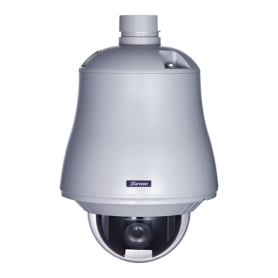
1.3. Technical Specifications Product Images for CAM6xxx Series CAM6120 CAM6160 CAM6180 CAM6351 Model List for CAM6xxx Series CAM61xx Series CAM6120 CAM6160 CAM6180 25x Zoom CCD D/N 25x Zoom CCD D/N 35x Zoom CCD D/N Indoor IP Speed Dome Outdoor IP Speed Dome... -
Page 19: Specifications For Cam6120/6160/6180
Specifications for CAM6120/6160/6180 Model Name CAM6120 CAM6160 CAM6180 25x Zoom CCD D/N 25x Zoom CCD D/N 35x Zoom CCD D/N Outdoor IP Description Speed Dome Indoor IP Speed Dome Outdoor IP Speed Dome Image Sensor 1/4" D1 SONY EXview HAD CCD 3.43 - 120 mm autofocus lens,... - Page 20 IPv4, ARP, TCP, UDP, ICMP, DHCP, NTP, DDNS, SMTP, FTP, HTTP, CIFS, PPPoE, UPnP, RTP, Protocols RTSP, RTCP, 3GPP Ethernet 10/100 Base-T / RJ45 Local Storage RS-485 1 (2 pin on terminal block) Surveon SDK 2.0 Microsoft Windows XP/Vista/7 Browser Microsoft IE 6.0 or above Software Surveon VMS 2.4.1 Temperature Operation: -10~50°C (14~122°F)
-
Page 21: Specifications For Cam6351
Specifications for CAM6351 Model Name CAM6351 Description 20x Zoom Full HD D/N Outdoor Speed Dome Network Camera Image Sensor 1/2.8" 2 megapixel SONY low light CMOS Lens 4.7 ~ 94 mm autofocus lens, F1.6 (wide) - F3.7 (tele) 48dB Day/Night ICR IR LED 0.01 Lux @ F1.6 (B/W) Min Illumination... - Page 22 PPPoE, UPnP, IGMP, SNMP, QoS, IEEE 802.1X, ONVIF Ethernet 10/100 Base-T / RJ45 microSD/SDHC x 1 Local Storage (Class 4/Class 6 only) RS-485 Surveon SDK 2.0 Microsoft Windows XP/Vista/7 Browser Microsoft IE 6.0 or above Software Surveon VMS 2.4.7 Temperature Operation: -40~50°C (-40~122°F)
-
Page 23: Chapter 2. Hardware Overview
Chapter 2. Hardware Overview 2.1. Overview CAM6120 CAM6160/6180 1. Bottom Chassis/Upper Base 2. Camera Case 3. Dome Cover 4. Power In Jack 5. RS-485 In/Out Terminal 6. Video Out Jack 7. Alarm In/Out Connector 8. RJ45 Network Connector... -
Page 24: Bottom View - Cam6351
Bottom View - CAM6351 1. LAN Connector 2. Alarm In/Out Connector 3. Power Connector Slot 4. Micro SD Card Slot 5. Reset Button 6. Audio In/Out Connector... -
Page 25: Dimensions
2.2. Dimensions CAM6120... -
Page 26: Cam6160/6180
CAM6160/6180 Unit: mm (inches) -
Page 27: Cam6351
CAM6351 Unit: mm (inches) -
Page 28: Setup For Cam6120/6160/6180
2.3. Setup for CAM6120/6160/6180 DIP Switches Alarm Out Mode Alarm Out Mode can be set as NC (normally close) or NO (normally open). RS-485 Protocol Switch 1, 2 - RS-485 IN (1), OUT (2) Terminal Resistor ON/OFF ; o Daisy-chained Connection: Set RS-485 In and Out terminal resistors ON (Default). -
Page 29: Camera Id Switch
o On –MLP2 (Merit Lilin Protocol 2) o Off – MLP1 (Merit Lilin Protocol 1) Camera ID Switch MLP1 When MLP1 is chosen, the up to 64 cameras can be addressed. Each camera should be assigned a separate ID according to the following illustration:... - Page 30 MLP2 When MLP2 is chosen, the up to 256 cameras can be addressed. Each camera should be assigned a separate ID according to the following illustration:...
-
Page 33: Cabling Specifications
Cabling Specifications AC24V Power Cable Recommend Cable: Accessory Connector Information Note: Connect this to 24VAC class 2 power supply (optional accessory) only. -
Page 34: Twisted Pair
RS-485 Twisted Pair Video Out BNC o Video Signal Output CVBS 1.0Vp-p 75 BNC o Recommend Data Cable: 5C2V Alarm In/Out Each fast dome contains 6 alarm inputs and 1 alarm output. o Alarm Input Voltage: 5.6V max. o Alarm Output: 1A 24VDC o Recommend Data Cable: o UL26 AWG 80 C 300V o UL24 AWG 80 C 300V... -
Page 35: Setup For Cam6351
2.4. Setup for CAM6351 Preparation for Dome Camera Setup 1. Unpack the dome package and take out the dome body. 2. Remove the plastic wrapping on the dome cover. 3. Remove the Styrofoam sheet from the inside of the dome cover. 4. -
Page 36: Camera Cable Connections
7. Gently pressure the dome cover downward with two hands on the side of it. 8. Use one M3 Screw and the original two screws to screw the dome cover and camera body together. Camera Cable Connections Connecting Power Pin definitions of the power connector: Definition Color of Power Wire Connected AC 24-... -
Page 37: Connecting Power With Optional Ac Adapter
1. Connect the power wires of AC adapter with the power connector. Please check the colors of the power wires carefully, and screw them with the connector properly. 2. Insert the power connector into the power connector slot. Connecting Power with Optional AC Adapter Adjust the power selector according to the practical local power voltage, and connect the power cord with the adapter and power outlet. -
Page 38: Connecting Lan Cable
Note: Contact your dealer for purchasing the adapters. Connecting LAN Cable 1. Connect one end of the LAN cable to the LAN connector of the network Speed Dome Camera, and the other end of the cable to the network switch or PC. 2. -
Page 39: Applying Audio (Optional)
Definition Definition ALARM_OUT_COM_2 ALARM_OUT_NO_1 ALARM_OUT_NC_1 ALARM_IN_4 ALARM_OUT_COM_1 ALARM_IN_3 ALARM_OUT_NO_2 ALARM_IN_2 ALARM_OUT_NC_2 ALARM_IN_1 Applying Audio (Optional) Set up the audio according to the audio pin definition. Definition LINE_OUT LINE_IN Inserting and the Micro SD Card (Optional) 1. Make sure the golden finger of the Micro SD card is facing downwards. 2. -
Page 40: Chapter 3. Indoor Dome Installation(For Cam6120)
Chapter 3. Indoor Dome Installation(for CAM6120) 3.1. Indoor Installation Structural Drawing Embedded Mounting Attached Mounting... -
Page 41: Embedded Mounting (False Ceiling)
3.2. Embedded Mounting (False Ceiling) Step1 Ceiling Preparation "( . Drilla3 32 2 4mm holeatthecenterofthe Useapencilandacompass tomarkacircle6 7 Drill a 3/32" (2.4mm) hole at the center of the chosen area. Use a pencil and a compass to mark a circle 6.7" (170mm) in diameter and cut the circle. -
Page 42: Step4 Attach The Camera Body And Base
Separate the camera body and space. Setting Fast Dome ID, Alarm Out Mode, RS-485 Protocol. Step4 Attach the Camera Body and Base Attach camerabody Turn camerabody Tighten the two screws Attach camera body to the base. Note: Check if the position connector is correct or not. Turn the camera body counterclockwise to tight position. -
Page 43: Step7 Install Camera Body, Decoration Ring And Dome Cover
Step7 Install Camera Body, Decoration Ring and Dome Cover Putcamerabodyand Turnthecamerabody Tightenthreeblack Insert on decoration Put the camera body and the fix ring into the hole. Turn the camera body clockwise to tight position. Tighten three black screws. Put on decoration ring. Turn theringclockwise Attach domecoverto Turnthedomecover... -
Page 44: Step2 Camera Setting
Separate the camera Set all ofcontrolcableinmiddlepositionand Attach base to ceiling Separate the camera body to the base. Set all the control cables in the middle position and through the hole of ceiling. Install the rubber cover on the cable outlet of base, or set the control cables on the cable outlet of base. -
Page 45: Step4 Connection
Step4 Connection Connect RS-485 cable. Connect video signal cable. Connect alarm cable. Connect network cable. Step5 Install Dome Cover Turn domecover Install dome cover Install the dome cover onto the camera body. Turn the dome cover clockwise to tight position. Note: After the dome cover is attached, use glass-cleaning cloth to clean it. -
Page 46: Step2 Connection
Turn the camera cover clockwise. Separate the camera body to the base. Set all the control cables in the middle position and Install the rubber cover on the cable outlet of base. Step2 Connection Connect RS-485 cable. Connect video signal cable. Connect alarm cable. -
Page 47: Step5 Attach The Camera Body And Base
Step5 Attach the Camera Body and Base Attach camerabody Turn camerabody Tighten the two screws Attach camera body to the base. Note: Check if the position connector is correct or not. Turn the camera body counterclockwise to tight position. Tighten the two screws to fix the camera body. Step6 Install Dome Cover Turn domecover Install... -
Page 48: Camera Deployment
3.5. Camera Deployment Email server Email server Router Router Internet Internet Router Router VMS Client 3.6. Before You Start Please prepare a PC with Windows (XP or above) and web browsers (Internet Explorer 6.0 or above) installed. -
Page 49: Chapter 4. Outdoor Dome Installation (For Cam6160/6180)
Chapter 4. Outdoor Dome Installation (for CAM616 0/6180) 4.1. Outdoor Dome Mounting Step1 Separate the bracket from the base of bracket Untighten the four screws from the bracket. Separate the bracket and base of bracket from top of the bolt. Step2 Fix the base of bracket on the wall 70mm 60mm... - Page 50 Attach outdoor speed dome camera to Attach the outdoor speed dome camera to the bracket, and tighten the three screws. Step4 Fast Dome Camera Setting Untigten the three screws from the dome cover. Separate the dome cover from the camera case. Setup ID numbers of the fast dome camera and RS-485 protocol.
- Page 51 Connect alarm cable. Connect network cable. Connect AC 24V or AC100/240 power cable. After connecting all of the cables, put all of them in the tube of bracket. Put iron slice of the fixed cable on the bracket, and tighten the two screws to fix their own slice.
-
Page 52: Camera Deployment
4.2. Camera Deployment Email server Email server Router Router Internet Internet Router Router VMS Client 4.3. Before You Start Please prepare a PC with Windows (XP or above) and web browsers (Internet Explorer 6.0 or above) installed. -
Page 53: Chapter 5. Outdoor Dome Installation (For Cam6351)
Chapter 5. Outdoor Dome Installation (for CAM635 5.1. Ceiling Mounting Package Contents of Ceiling Mounting Kit M8x12 Screw x1 Spring Washer-8 x1 Pendant Tube Washer x1 Rubber Washer-8 x1 Sponge x2 Items Needed Waterproof Rubber x1 (provided with the package of the camera) M5 Screw x1 (provided with the package of the camera) Screws and Screw Anchors for fixing the Straight Tube onto the ceiling (provided by users) - Page 54 3. Fix the Straight Tube to the ceiling with screws and screw anchors. 4. Fit the Waterproof Rubber to the Straight Tube. (You may turn the Waterproof Rubber inside out, which is shown in the picture below, to make the fitment easier.) 5.
- Page 55 6. After threading the cables, please block the cable entry hole with the supplied sponge(s) to avoid insects entering the tube. 7. Fix the Outdoor Flange to the Straight Tube with the supplied screw (M8x12) and washers. Then adjust the Waterproof Rubber. 8.
-
Page 56: Wall Mounting
5.2. Wall Mounting Package Contents of Wall Mounting Kit M8x12 Screw x1 Spring Washer-8 x1 Pendant Tube Washer x1 Rubber Washer-8 x1 Sponge x1 Items Needed Waterproof Rubber x1 (provided with the package of the camera) M5 Screw x1(provided with the package of the camera) Screws and Screw Anchors for fixing the Pendant onto the wall (provided by users) Tools Needed Electric Drill... - Page 57 3. Fit the Waterproof Rubber to the Pendant. (You may turn the Waterproof Rubber inside out, which is shown in the picture below, to make the fitment easier.) 4. Run the cable(s) through the Pendant. 5. Please block the cable entry hole with the supplied sponge to avoid insects entering the Pendant.
- Page 58 M8x12 screw Spring washer Pendant tube washer Rubber washer 7. Mount the Dome Camera to the Outdoor Flange. Rotate the dome body and make sure the thread holes on the Lock Screw Plate and Outdoor Flange are aligned. Then screw the M5 Screw.
-
Page 59: Camera Deployment
5.3. Camera Deployment Speaker Amplifier-enabled Email server Email server Microphone Router Router Internet Internet Router Router Client 5.4. Before You Start Please prepare a PC with Windows (XP or above) and web browsers (Internet Explorer 6.0 or above) installed. -
Page 60: Chapter 6. Connecting To The Network Camera (For Cam6120/6160/6180)
Web Browser – A simple web-based interface. Internet Explorer is the • recommended web browser for use with Surveon network cameras, and our examples will be from this browser. Usage on other browsers will be similar. RTSP Player – These include common streaming media players, such as •... -
Page 61: Connecting With A Web Browser
6.1. Connecting with a Web Browser Obtaining IP address through the IP Utility The IP address can be obtained using the IP Utility in your product CD: 1. Double click Start SearchToolInstall.exe to begin the utility installation. 2. After the installation is complete, click the Auto Search button or click Camera >... -
Page 62: Logging Into The System
Logging into the System The following information will prompt for logging in: Username – The username for the domain. Default is always admin. Password – The password for the domain. Default is always admin. Click OK. Installing Active X Components in Internet Explorer You may be prompted to install ActiveX®... -
Page 63: Logging Out Of The System
Search for Download signed ActiveX controls. Under this heading select Prompt and then click OK. Continue installing the Active X components. After installing ActiveX, go to Tools > Internet Options > Trusted Websites> Sites and add the IP Address of the camera. Logging Out of the System Logging off of the camera can be performed by closing the browser window. - Page 64 The help manual is organized so that it matches the system menus, with sections corresponding to each settings menu and the Live-view window.
-
Page 65: Connecting With An Rtsp Player
6.2. Connecting with an RTSP Player Surveon cameras support connections through RTSP Media Players such as Real Player and QuickTime Player. We will use Real Player as an example in this section. Launch Real Player. Select File > Open URL, to open a URL dialog box. -
Page 66: Chapter 7. Configuration Through Web Interface (For Cam6120/6160/6180)
Chapter 7. Configuration through Web Interface (f or CAM6120/6160/6180) Camera configurations can be done through web interface and IP Utility. **For web interface, please look into this chapter; for IP Utility, please refer to Chapter 8. Web Interface IP Utility... - Page 67 Reboot Camera Search Login Properties Delete from Tool Clearing and Setting Status Camera Group Actions Configuration Settings Focus Tool...
-
Page 68: Interface Layout
7.1. Interface Layout This section demonstrates the layout of the network camera’s main interface. The 4 main areas on the interface are: 1. Menu Bar - The links on this bar allow users to toggle between live- view and settings screens, as well as logout and pull up the help menu. 2. -
Page 69: Control Descriptions
“ESC” to return to windowed view. Image Capture: When clicked, captures the current screen as an image in a new pop-up window and saves it in C:\Surveon\Record. This location can be changed under Settings > Recording > Recording Basic Settings. file name “Camera... - Page 70 Control Description Language: Sets the UI language. Available languages include English, Simplified Chinese, and Traditional Chinese. Streams: Allows users to choose which camera stream to view. The indicator above the stream will turn light green when the stream is selected. Video Format: Sets the compression format for the current stream.
-
Page 71: Settings
Users may replace the default name with a new name consisting of alphanumeric characters, spaces and the ":" character. Camera Name: by default set to "Surveon + model name"; after • selecting Camera Name” from Settings > Video & Audio > Basic Settings, the Camera Name will show on the display. -
Page 72: User Account
User Account The User Account section, found under General > User Account, controls the user account information and privileges. There are two pre-configured accounts: admin - This is the default administration account, and cannot be • deleted. guest - This is an account with only live view capability. •... - Page 73 Adding Accounts In General > User Account under the User Account heading, click on “Add”. Up to 10 accounts can be added to the system. All User Names and Passwords must be combinations of alphanumeric characters, “:”, “-“, “_” between 4 and 20 characters in length, and must begin with an alphabet letter.
- Page 74 Editing Accounts In General> User Account under the User Account heading, select an existing account by clicking on the account entry. The entry will be highlighted in yellow. Clicking Edit will allow you to change the following fields: User Group - The system allows for 2 types of users. •...
-
Page 75: Date & Time
Date & Time Date and time settings can be accessed at General > Date & Time. Current Date & Time displays the current system date and time. Time Zone Settings The time zone can be set using the dropdown menu. This menu is only applicable when selectable when Synchronize with NTP Server is chosen under Time Settings. - Page 76 Day Light Saving Users can set the Day Light Saving Time by ticking on Enable Day Light Saving. Click OK to save or Cancel to abort the changes before you leave the page.
-
Page 77: Network
Network The network settings, including network configuration, port configuration, and universal plug and play (UPnP) settings are used to configure camera connectivity. These settings are found under the Settings > Network context. Network Configuration These settings are used to configure basic network access for the camera. They are found under Network >... - Page 78 Secondary DNS fields. The network camera can be connected to the network upon completion. PPPoE Settings This feature is disabled by default. Connecting to the network using PPPoE (Point-to-Point Protocol over Ethernet) requires a user name and password from your ISP (Internet Service Provider). Select Enable PPPoE and fill in valid user name and password to connect the camera to the Internet.
-
Page 79: Port Settings
Port Settings Ports are a software construct used to multiplex the transmission information to and from the camera. They act as separate endpoints within an IP address where software "listens" for incoming information. This section, which can be accessed under Network > Port Settings, includes HTTP Port Settings, RTSP Settings and RTP Multicast Settings. - Page 80 Note: The RTP port number must be an even number. After entering the RTP port number, the RTCP port number will automatically be set to the RTP port number + 1. RTP Multicast Settings Tick Enable RTP Multicast to set up multicast via the RTP protocol. The RTP Multicast video/audio port and group address can also be set.
-
Page 81: Upnp
UpnP Universal plug and play (UPnP) is a protocol that simplifies the implementation of networks by allowing new hardware to connect seamlessly to a network. The settings for this feature can be found under Network > UPnP. To enable UPnP, first check the Enable UPnP box. If you wish to change the default values, there are two fields that can be edited. -
Page 82: Video & Audio Settings
Video & Audio Settings Video and audio are the heat of a network camera's functionality. The settings for video and audio can be found under Settings > Video & Audio. Under this section, you can access basic video and audio settings, video appearance parameters, video stream settings, as well as audio parameters. -
Page 83: Image Appearance Settings
There are two tabs, Image Attributes and Sensor Configuration, as well as Advanced Settings. Image Appearance (for CAM6120/6160/6180) Day mode/Night mode - Sets the day (color) and night (black and white, IR cut filter off where applicable.) Night mode sacrifices color information to produce a clear picture with less light. - Page 84 Saturation - Adjusts the saturation of the image. • AGC Gain - Automatic gain control (AGC) adjusts the video gain level • to a variety of inputs to preserve a correct exposure levels. Flickerless - Reduces flickering caused by the difference in frequency •...
-
Page 85: Video Streams
Video Streams The configuration for video streams, including resolution, frame rate and image quality parameters can be found under Video & Audio > Video Streams. The page is split into settings for 2 streams. Common settings are: Video format - The compression format for the video stream. •... -
Page 86: Audio Settings
Video Frames per Second - Sets the number of frames per second. 1, • 3, 5, 10, 15, 20, 25, 30 FPS are possible values. Key Frame Interval - Sets the period between minimally compressed • recovery frames that don't require other video frames to decode. 1/4s, 1/2s, 1s, 2s, 3s, and 4s are possible values. -
Page 87: Ptz
CAM61xx Series have built in pan-tilt-zoom (PTZ) functionality, and is able to quickly change the camera’s viewing angle to pursue action. The PTZ menu Settings > PTZ > PTZ Settings allows configuration of PTZ functionality. Pan/Tilt Control: The four directional buttons pan and tilt the camera view in the direction pressed. -
Page 88: Ptz Presets
Tilt Speed: Determines the amount the camera will tilt with each • press of the Pan/Tilt Control. PTZ Presets Up to 126 presets can be saved in the camera’s memory. Adding a Preset To add a preset: 1. Set the camera to the desired preset location using the PTZ, focus and iris controls. -
Page 89: Recording
Recording The Recording menu, Settings > Recording, deals with recording settings and managing recorded video files. Recording Basic Settings Recording basic settings, Recording > Recording Basic Settings are parameters which deal with the recording location and scheduling. The following parameters can be configured within this menu: Manual Record To - Defines the path for manual recording. -
Page 90: Event Notification
Event Notification Event Notification settings, found under Settings > Event Notification, deal with the event detection, scheduled recording, and notification abilities of the camera. Event Server The event server, which can be configured under Event Notification > Event Server, is the communications center of the camera. This section deals with the configuration of E-mail and FTP notifications, as well as remote recording. - Page 91 Password - The password of the e-mail account. • SMTP Server Port - the SMTP port of the email server; Default 25. • Test - Click this button to send a test email. E-mails will only be sent • if all parameters are entered correctly. FTP Settings FTP settings are used to configure recording to a remote location via the file transfer protocol.
-
Page 92: Motion Detection
Motion Detection The motion detection functionality of the camera can be found under Event Notification > Motion Detection. Motion Detection Window Management To detect motion, first a detection window must be created. First click the Window Settings tab to enter the window configuration, and click New to add a new detection window. - Page 93 Activating and Scheduling Motion Detection Motion detection is activated by checking the Enable Motion Detection box. Activate Motion Detection By: denotes when motion detection will be triggered as an event. Auto – As long as Enable Motion Detection is checked, an event is •...
-
Page 94: Tampering Detection
Tampering Detection Tampering detection is similar to motion detection in that it detects where there is a sudden unexpected change in the whole camera view. Parameters for this feature are found under Event Notification > Tampering Detection. Tampering alarm handling and notifications can be configured under Event Settings. -
Page 95: Di & Do
DI & DO Note: CAM61xx series do not support D1 & DO. Event Settings Event settings deal with alarm handling and notification, as well as feature scheduling. These settings can be found under the Event Notification > Event Settings menu. The event handler is rule based. - Page 96 Adding/Editing an Event Rule The Add and Edit screens contain the following triggering actions: Note: If editing a rule that has not been triggered, the rule will not be triggered after until after editing is complete. If the rule is triggered, any changes will not be applied until the current trigger is resolved.
- Page 97 boxes, and fill in a start time and end time for motion detection in the From: and To: boxes. Never – The event is never triggered. • Enable Triggering By After the frequency is selected, triggering conditions can be set. Multiple conditions can be set at once.
- Page 98 Email – E-mails notifications to the email address specified in the • Event Server settings. If this option is chosen, fill in the following: o Subject - The subject line of the notification e-mail. o Additional Information - Contents of the notification e-mail. o Snapshot/Video Clip - Choose to send a snapshot or video attachment from 5s before to 30s after the trigger.
- Page 99 Name - Specifies the name of the Event. • Set Time Interval (When Activated) - The trigger time of the event • (00:00 to 23:59). Enable Triggering By The next step is to specify the frequency of trigger response. 3 options are available: Always - The default setting;...
- Page 100 o Additional Information - Contents of the notification e-mail. o Snapshot/Video Clip - Choose to send a snapshot or video attachment from 5s before to 30s after the trigger. FTP - uploads a snapshot or video clip to a FTP location specified in •...
-
Page 101: System
System The system settings, which deal with hardware and firmware parameters, logs, and configuration lists, can be found under Settings > System. MicroSD Card Management Note: CAM61xx series do not support Micro SD Card Management. System Status The camera status can be found under System > System Status. This section displays useful system information including: Network Configuration defined manually or obtained from DHCP •... -
Page 102: System Log
System Log The system log, System > System Log, provides a log for system messages and events. The log lists important information such as login information, changes to camera settings (both successful and unsuccessful), triggered events, and error messages. This information can be very useful in the event of a camera failure or unauthorized entry. -
Page 103: Firmware Upgrade
When the LED indicator turns green, the firmware is upgraded successfully. Emergency Recovery Procedure If the status LED shows steady amber for over 1 minute, the camera will become unresponsive and the upgrade process may have failed. Please contact with your reseller Surveon technical support support@surveontech.com. -
Page 104: Resetting To Factory Default Settings
Resetting to Factory Default Settings To reset the device to the factory default settings: Make sure the device is in operation mode. Using a needle or similar object to press and hold the Reset button until the camera restarts (about 2 seconds). The status LED will change to amber during startup. - Page 105 To check for updated information on your camera, or for any other questions, please refer to http://www.surveontech.com/support/faq.asp or contact technical support at support@surveontech.com.
-
Page 106: Export/Import & Reboot
Click Browse: to browse your PC for the configuration file. Click Apply to import the settings. The IP Utility is a set of tools for Surveon network cameras. It includes tools to create, modify, delete and manage groups within the camera; The IP Camera Utility also provides tools to perform simple connectivity configuration, firmware upgrades and reboot operations. -
Page 107: Chapter 8. Configuration Through The Ip Utility(For Cam6120/6160/6180)
Chapter 8. Configuration through the IP Utility(for CAM6120/6160/6180) Camera configurations can be done through web interface and IP Utility. **For IP Utility, please look into this chapter; for web interface, please refer to Chapter 7. Web Interface IP Utility General... -
Page 108: Camera Search
Reboot Camera Search Login Properties Delete from Tool Clearing and Setting Status Camera Group Actions Focus Tool... -
Page 109: Overview
8.1. Overview The IP Utility is a set of tools for Surveon network cameras. It includes tools to create, modify, delete and manage groups within the camera; The IP Camera Utility also provides tools to perform simple connectivity configuration, firmware upgrades and reboot operations. The utility is intended to simplify the configuration and management of multiple cameras. - Page 110 2. Click Next to continue with installation. 3. Fill in the Folder field to specify the installation path. Clicking Browse… pulls up a file system browser. Clicking Disk Cost will display free space and the space the utility will take up on disks. 4.
-
Page 111: Ip Utility Basics
Starting the IP Utility To start the IP Utility, double-click the IP Utility shortcut on your desktop or go to Start > Program Files > Surveon > IP Utility > IP Utility. Note: On startup, the utility will automatically scan for Surveon IP Cameras on the same subnet as the computer. -
Page 112: Camera Actions
8.4. Camera Actions This section displays camera information, including the IP, Name, Model, MAC Address, Status and Network Mask. Search Search updates the details for the cameras listed, as well as locates any new cameras connected on the same subnet. The search is performed every time the IP utility starts. -
Page 113: Properties
3. Click OK to set the username and password. Note: To perform further configuration, please make sure that the User set here has administrator privileges. The default Username/Password for Surveon Cameras is admin/admin. Properties The properties of a camera can be viewed by following these steps: 1. -
Page 114: Delete From Tool
Delete from Tool 1. Select one or more cameras by checking the box in the first column of their listing. 2. Right click the camera(s) which you want to delete from the tool and select Delete from Tool. The camera will be removed from the listings. -
Page 115: Select All
Select All In a group context, right clicking a camera, and selecting Select All will select all the cameras in the group. Rebooting Camera In certain cases it may be necessary to reboot the camera. To do this: 1. Select a camera by checking the box in the first column of its listing. 2. -
Page 116: Set Ip
Set IP The IP Address of a camera can be set by following these steps: 1. Click the Set IP button. 2. You can choose to obtain an IP address from DHCP or assign a fixed IP. 3. Select one or more cameras by checking the box in the first column of their listing. -
Page 117: Link To Camera Web Interface
Link to Camera Web Interface Link to Camera 1. Select a camera by checking the box in the first column of its listing. 2. Click the Link to Camera button or click to Camera > Link to Camera in the menu bar. The camera’s live view webpage will open in a browser window. -
Page 118: Clearing And Setting Status
Clearing and Setting Status Clear New Status When a camera is first displayed in the tool, the status column will display the status “New”. These cameras will show up in the All Devices > New Devices group. This function clears the status. To perform this function: 1. - Page 119 These camera(s) will show up in the All Devices > New Devices group. The camera(s) will still be listed under All Devices > Warning/Errors if applicable.
-
Page 120: Camera Group Actions
8.5. Camera Group Actions The Camera Group frame contains a simple tree containing group listings. There are two pre-defined subsections. All Devices - contains all the cameras in the tool, as well as predefined groups New Devices and Warnings/Errors MyGroup – contains only user defined groups. Add Group 1. -
Page 121: Rename Group
3. The system will ask to confirm the deletion. Click Yes to delete the group. Note: Groups may be deleted, even if they contain cameras. Rename Group 1. Expand MyGroup and right-click the group you wish to rename. 2. Choose Rename Group. Alternatively, click the group and choose Rename Group from the Group menu. -
Page 122: Move To Group
Move to Group This function moves the selected camera(s) from a group to another group. 1. From the Camera Group window select a group under MyGroup. 2. Select one or more cameras from the existing group by checking the box in the first column of their listing. -
Page 123: Copy To Group
Copy to Group This function copies the selected camera(s) from a group to another group. 1. From the Device Group window select a group. 2. Select one or more cameras from the existing group by checking the box in the first column of their listing. 3. -
Page 124: Configuration Settings
8.6. Configuration Settings Configuration can be downloaded and updated by selecting Camera > Configuration, or the process can be automated by downloading the configuration from one camera using the Download Configuration function, and then using the Update Configuration function to upload the changed configuration file. -
Page 125: Update Configuration
3. Click the Browse button to browse the computer and locate a destination. 4. Click Download to download the configuration file to the destination. Update Configuration 1. Select one or more cameras by checking the box in the first column of their listing. -
Page 126: Firmware Actions
8.7. Firmware Actions Download Firmware This function links to the user management page of the selected camera. 1. Select a camera by checking the box in the first column of its listing. 2. Right click the camera and select Maintenance > Download Firmware or click to Camera >... - Page 127 Note: You must be logged into the camera to update the camera firmware. 1. Select one or more cameras by checking the box in the first column of their listing. 2. Click the Update Firmware button; right-click the camera(s) which you want to update to and select Maintenance >...
-
Page 128: Focus Tool
8.8. Focus Tool The Focus Tool is used as a reference for focus precision. Click the Focus Tool button to open it. Information of Best Focus Value, Current Focus Value and Focus Percent will be shown at the bottom of the Focus Tool Window. You can click Refresh to get a new data after focus adjustment is done. -
Page 129: Chapter 9. Connecting To The Network Camera (For Cam6351)
Chapter 9. Connecting to the Network Camera (fo r CAM6351) 9.1. Accessing the Camera Setting the Camera's IP The network speed Dome camera’s default IP address is: 192.168.0.250. Therefore, to access the camera for the first time, set the PC’s IP address as 192.168.0.XXX;... - Page 130 Installing Active X Components in Internet Explorer (Optional) After connecting to the camera, the request for installing the ActiveX control will appear just below the URL bar. Right Click on the information bar, and click Install ActiveX Control… to permit ActiveX control installation. In the pop-up security warning window, click Install to start downloading DC Viewer software on the PC.
-
Page 131: Chapter 10. Configuration Through Viewer Window Interface (For Cam6351)
Chapter 10. Configuration through Viewer Window Interface (for CAM6351) Overview 10.1. The Full HD Speed Dome IP Camera transmits digital video and audio data using wire connection. Live video can be monitored and recorded from window-based computer via network. The video encoder supports real-time Main Profile H.264 Full HD resolution. Simultaneous dual streams, H.264/H.264 and H.264/MJPEG, are available for various network applications via speeding or limited bandwidth. - Page 132 The five setting tabs on the interface are: 1. Home: Users can monitor live video of the targeted area. 2. System: The Administrator can set host name, system time, root password, network related settings, etc. Further details will be interpreted in the section System.
-
Page 133: Home Page
10.3. Home Page Click on the tab Home to access the home Page. There are several function buttons on the Home pate. Detailed information of each item is as described in the following chapter. Function Items on the Home Page Multiple Languages Support Multiple languages are supported, including German, English, French, Italian, Korean, Simplified Chinese, Russian, etc. -
Page 134: Video Streaming Pause /Restart Button
Note: For users with Windows 7 operating system, it is required to log on as an Administrator to implement the Web Recording function. Video Streaming Pause /Restart Button (Pause/Restart) Click on the Stop Button to disable video streaming, the live video will be displayed as black. -
Page 135: Pan/Tilt Control
Pan/Tilt Control Users can implement pan/tilt control by first moving the cursor to the live video pane; then left click and drag the pointer in any direction. Optical/Digital Zoom Control In Normal View display mode, users can implement zoom in/out by first moving the cursor to the live video pane and then rotating the mouse wheel. -
Page 136: System
System The System Setting can be found under the path: System > System. Host Name The name is for camera identification. If alarm function is enabled and is set to send alarm message by Mail/FTP, the host name entered here will display in the alarm message. -
Page 137: Https
Note: The following characters are valid: A-Z, a-z, 0-9, !#$%&’-.@^_~. Add user Type the new user's name and password and click on Add to add the new user. Both user name and password can be up to 16 characters. The new user will be displayed in the user name list. -
Page 138: Create Self-Signed Certificate
a Certificate Authority (CA) or creating a self-signed HTTPS certificate, as described below. Create Self-signed Certificate Before a CA-issued certificate is obtained, users can create and install a self-signed certificate first. Click on Create Button under Create Self-signed Certificate and provide the requested information to install a self-signed certificate for the IP Camera. -
Page 139: Ip Filter
State or Province Enter the local administrative region. Locality Enter other geographical information. Organization Enter the name of the organization to which the entity identified in Common Name belongs. Organization Unit Enter the name of the organizational unit to which the entity identified in Common Name belongs. -
Page 140: Network
The IP Camera is allowed to access a network protected by 802.1X/EAPOL (Extensible Authentication Protocol over LAN). Users need to contact with the network administrator for gaining certificates, user IDs and passwords CA Certificate The CA certificate is created by the Certification Authority for the purpose of validating itself. - Page 141 Note: Please make the record of the IP Camera’s MAC address, which can be found in the label of the camera, for identification in the future. Use fixed IP address To setup static IP address, select Use fixed IP address and move the cursor to the IP address blank and insert the new IP address, ex.
-
Page 142: Qos
RTSP Port The default setting of RTSP Port is 554; the setting range is from 1024 to 65535. MJPEG over HTTP Port The default setting of MJPEG over HTTP Port is 8008; the setting range is from 1024 to 65535. HTTPS port The default setting of HTTPS Port is 443;... -
Page 143: Snmp
SNMP The SNMP (Simple Network Management Protocol) setting can be found under this path: System > Network > SNMP. With Simple Network Management Protocol (SNMP) support, the IP Camera can be monitored and managed remotely by the network management system. SNMP v1/ v2 Enable SNMP v1/ v2 Select the version of SNMP to use by checking the box. -
Page 144: Ddns
UPnP Setting Enable UPnP When the UPnP is enabled, whenever the IP Camera is presented to the LAN, the icon of the connected IP Cameras will appear in My Network Places to allow for direct access. Note: To enable this function, please make sure the UPnP component is installed on your computer. -
Page 145: Mail
Mail The Mail setting can be found under this path: System > Mail. The Administrator can send an e-mail via Simple Mail Transfer Protocol (SMTP) when an alarm is triggered. SMTP is a protocol for sending e-mail messages between servers. SMTP is a relatively simple, text-based protocol, where one or more recipients of a message are specified and the message text is transferred. -
Page 146: Alarm Setting
Alarm Setting Alarm Switch The Administrator can enable or disable the alarm function. Alarm Type Select an alarm type, Normal Close or Normal Open, that corresponds with the alarm application. Triggered Action (Multi-option) The Administrator can specify alarm actions that will take at an alarm occurrence. All options are listed as follows: Enable Alarm Output 1/2 Select these items to enable alarm relay outputs. - Page 147 of time. As for other function modes, the camera will keep executing the specified function; to stop the performance, simply change the camera’s status. Note: The dwell time is only adjustable when selecting Preset as the alarm action. When the dwell time is up, the Camera will go back to its trigger position and recheck alarm pin status.
-
Page 148: Motion Detection
Add Sequence Number Suffix (No Maximum Value) File name: imageXXXXXXX.jpg X: Sequence Number Add Sequence Number Suffix (Limited Value) File Name: imageXX.jpg X: Sequence Number The file name suffix will end at the number being set. For example, if the setting is up to “10,”... -
Page 149: Motion Detection
If Motion Detection function is activated, the pop-out window (Motion) with indication of motion will be shown. When motion is detected, the signals will be displayed on the Motion window as shown below. Motion Detection Users are able to turn on/off Motion Detection. Default setting is Off. Motion Detection Setting Users could adjust various parameters of Motion Detection in this section. -
Page 150: Triggered Action (Multi-Option)
Triggered Action (Multi-option) The Administrator can specify alarm actions that will take when motion is detected. All options are listed as follows: Enable Alarm Output 1/2 Check the item and select the predefined type of alarm output to enable alarm relay output when motion is detected. -
Page 151: File Name
File Name The uploaded image’s filename format can be set in this section. Please select the one that meets your requirements. Save Click on the Save Button to save all the Motion Detection settings mentioned above. Tampering The Tampering setting can be found under this path: System > Tampering. Tempering Alarm function helps the IP Camera against tampering such as deliberate redirection, blocking, paint spray, and lens cover, etc through video analysis and reaction to such events by sending out notifications or uploading snapshots to the... -
Page 152: File Name
Send Alarm Message by FTP/E-Mail The Administrator can select whether to send an alarm message by FTP and/or E- Mail when tampering is detected. Upload Image by FTP Select this item and the Administrator can assign a FTP site and configure various parameters. -
Page 153: Device Information
To implement Micro SD card recording, please go to the Recording page (refer to the section Recording) for activation. Note: Please format the Micro SD/SDHC card when using for the first time. Formatting will also be required when a memory card already being used on one camera and later transferred to another camera with different software platform. -
Page 154: Recording (Local Recording)
Download To open/download a video clip, select the file first, and then click on the Download Button below the Recording List field. The selected file window will pop up. Click on the AVI file to directly play the video in the player or download it to a specified location. -
Page 155: View Log File
View Log File The View Log File function can be found under this path: System > View Log File. Click on the link to view the system log file. The content of the file provides useful information about configuration and connections after system boot-up. View User Information The View User Information function can be found under this path: System >... -
Page 156: Reboot
Reboot Click on the Reboot Button, and the system will restart without changing current settings. Software Version The Software Version can be found under this path: System > Software Version. The current software version is displayed in the software version page. Software Upgrade The Software Upgrade setting can be found under this path: System >... -
Page 157: Export
Users can export configuration files to a specified location and retrieve data by uploading an existing configuration file to the IP Camera. Export Users can save the system settings by exporting the configuration file (.bin) to a specified location for future use. Click on the Export Button, and the popup File Download window will come out. - Page 158 Under Video Resolution section, select a preferred resolution setting. The available Video Resolution for MJPEG & H.264 format includes: MJPEG+ H.264 H.264 MJPEG BNC SUPPORT 720 x 480 (30fps)* √ 1920 x 1080 (30fps) 640 x 480 (30fps) √ 352 x 240 (30fps) √...
- Page 159 720 x 480 (30fps) √ 640 x 480 (30fps) √ 352 x 240 (30fps) √ 720 x 480 (30fps) √ 720 x 480 (30fps) 640 x 480 (30fps) √ 352 x 240 (30fps) √ 640 x 480 (30fps) 640 x 480 (30fps) √...
-
Page 160: Text Overlay Settings
1280 x 1024 (30fps) √ 1280 x 720 (30fps) √ 1024 x 768 (30fps) √ 800 x 600 (30fps) √ 720 x 480 (30fps) √ 640 x 480 (30fps) √ (*) Default Click on Save to confirm the setting. Text Overlay Settings Users can select the items to display data including date/time/text on the live video pane. -
Page 161: Gov Settings
If Flip is selected, the image will be rotated vertically. Mirror If Mirror is selected, the image will be rotated horizontally. 90 Degree Counter-/clockwise Selecting 90 Degree Counter-/clockwise will make the image 90° counter- /clockwise inversed. 180 Degree Rotate Selecting 180 Degree will make the image 180°inversed. Click on Save to confirm the setting. -
Page 162: Video Ocx Protocol
Video OCX Protocol The Video OCX Protocol setting can be found under this path: Streaming > Video OCX Protocol. In the Video OCX protocol setting page, users can select RTP over UDP, RTP over TCP, RTSP over HTTP or MJPEG over HTTP, for streaming media over the network. In the case of multicast networking, users can select the Multicast mode. -
Page 163: Mask Setting
Mask Setting Mask Color The selections of Mask color include red, black, white, yellow, green, blue, cyan, and magenta. Click Save to confirm the setting. Audio (Audio Mode and Bit Rate Settings) The Audio Mode setting can be found under this path: Streaming > Audio. In the Audio page, the Administrator can select one transmission mode and audio bit rate. -
Page 164: Ptz
10.6. PTZ Under the PTZ tab, there are categories including: Preset, Cruise, Auto Pan, Sequence, Home, Tilt Range, Camera- Exposure, Camera- WB, Camera- Misc1, Camera- Misc2, and Camera- Default. Preset The Preset Programming can be found under this path: PTZ > Preset. Totally 256 Preset Points can be programmed for the IP Camera. -
Page 165: Cruise Run
Cruise Run Select the specified Cruise Path from the drop-down list, click on the Run Button, and then the camera will start touring around as recorded. To view the camera touring around in full screen mode, please move the cursor onto the live view pane, right-click and left-click to select Full Screen. -
Page 166: Sequence
Sequence The Sequence Line Programming can be found under this path: PTZ > Sequence. The IP Camera supports totally eight Sequence Lines; each Sequence Line consists of up to 64 Preset Points. Please refer to the instructions below to program a Sequence Line. -
Page 167: Home Setting
automatically; this is the Home function. The Home function allows constant and accurate monitoring to avoid the Dome Camera idling or missing events. Home Setting Activate/Disable Home Function Select On or Off to activate or disable the Home function. Then click on the Set Button to save the setting. -
Page 168: Manual Mode
Manual Mode In this mode, users can change the Shutter speed (1/10000 to 1), Iris (F1.6 to F28), and Gain (1 to 15) manually. Camera - WB (White Balance) The White Balance Setting can be found under this path: PTZ > Camera - WB. A camera needs to find reference color temperature, which is a way of measuring the quality of a light source, for calculating all the other colors. -
Page 169: Camera - Misc 1 (Miscellaneous Setups Menu 1)
Camera - Misc 1 (Miscellaneous Setups Menu 1) The Miscellaneous Setting Menu 1 can be found under this path: PTZ > Camera- Misc 1. In the Camera—Misc (Miscellaneous) Setups Menu 1, users can set various camera parameters including Backlight Compensation (BLC), Sharpness, Exposures Compensation (ExpComp), Image Flip, Speed by Zoom and ICR function. -
Page 170: Speed By Zoom
Speed by Zoom Enable this function to adjust the pan/tilt speed automatically by internal algorithm when zooming. The larger zoom ratio leads to the lower rotating speed. Click on the Set Button to save the setting. ICR Function With the IR cut filter, the camera can still catch clear image at night time or in low light conditions. -
Page 171: Camera- Default
Select the video format that matches the present TV system. Click on the Set Button to save the setting. Camera- Default The Default Setting can be found under this path: PTZ > Camera- Default. In the Camera Default page, users can set the camera back to factory default settings simply by clicking on the Set Default Button. -
Page 172: Appendix C: Setup Internet Security
To improve browser performance, it is suggested to clean up the all the files in the Temporary Internet Files. The procedure is as follows: 1. Click on the Tools tab and select the Internet Options option. 2. Click on the Delete Button under Browsing History section. Then click on the Delete Files Button under the Temporary Internet files section. - Page 173 9. Run ActiveX controls and plug-ins. 10. Script ActiveX controls marked safe for scripting. 4. Click on OK to accept the settings and close the Security Settings window. 5. Click on OK to close the Internet Options screen. Close the browser window, and restart a new one later for accessing the camera.
Need help?
Do you have a question about the CAM6120 and is the answer not in the manual?
Questions and answers