Table of Contents
Advertisement
Advertisement
Table of Contents

Related Manuals for Surveon Speed Dome IP Camera Series


Summary of Contents for Surveon Speed Dome IP Camera Series
-
Page 1: User Manual
Speed Dome IP Camera Series User Manual Release 1.2... -
Page 2: Copyright Statement
Product specifications are also subject to change without notice. Trademarks Surveon and Surveon logo are trademarks of Surveon Technology Inc. Other names prefixed with “SMR” and “EMR” are trademarks of Surveon Technology Inc. Microsoft Windows and Windows are registered trademarks of Microsoft Corporation. -
Page 3: Revision History
Revision History Ver Version Description Date Initial release February 2013 UI Modified November 2013 Models added May 2014... -
Page 4: Table Of Contents
Table of Contents Copyright Statement ................. 2 Revision History ................3 Table of Contents ................4 Safety Precautions ................11 Device Site Recommendations ............11 Chapter 1. Product Overview ............. 12 1.1. Network Camera Introduction ........... 12 1.2. Features and Benefits ............. 13 1.3. - Page 5 Chapter 4. Connecting to the Network Camera ........33 4.1. Accessing the Camera ............. 33 Setting the Camera's IP ..............33 Chapter 5. Configuration through Viewer Window Interface ....... 35 5.1. Overview ................35 5.2. Interface Layout ..............36 5.3. Home Page ................37 Function Items on the Home Page ...........
- Page 6 Create Self-signed Certificate ........... 43 Install Signed Certificate ............44 Provide the Certificate Information ..........44 IP Filter ................45 IEEE 802.1X ................. 46 Network ................. 47 Basic ................. 47 QoS .................. 49 SNMP ................50 UPnP ................51 DDNS ..................52 Enable DDNS ...............
- Page 7 Tampering Duration ............... 60 Triggered Action (Multi-option) ..........60 File Name ................61 Save ................. 61 Storage Management (Local Recording) ..........62 Device Information ..............62 Device Setting ..............62 Disk Cleanup Setting .............. 62 Recording List ..............62 Recording (Local Recording) ............63 Activating Micro SD/SDHC Card Recording........
- Page 8 GOV Settings ............... 72 Video Compression ..............72 MJPEG Q (Quality) Factor ............72 H.264-1/ H.264-2 Bit Rate ............72 Display Compression Information ..........72 CBR Mode Setting..............72 Video OCX Protocol ..............73 RTP over UDP/ RTP over RTSP (TCP)/ RTSP over HTTP/ MJPEG over HTTP ..................
- Page 9 Video Mask ................79 Active Mask Function ............. 79 Camera - Exposure ..............79 Shutter Priority Mode ............. 79 Iris Priority Mode ..............79 Manual Mode ............... 80 Camera - WB (White Balance) ............80 Auto Mode ................80 Indoor/outdoor Mode ............. 80 ATW Mode (Auto Tracing White Balance) ........
- Page 10 Internet Security Level: Default ..........86 ActiveX Controls and Plug-ins Settings ......... 86...
-
Page 11: Safety Precautions
Safety Precautions Electric Shock Warning This equipment may cause electric shocks if not handled properly. Access to this equipment should only be granted to trained operators and maintenance personnel who have been instructed of, and fully understand the possible hazardous conditions and the consequences of accessing non-field-serviceable units such as the power supplies. -
Page 12: Chapter 1. Product Overview
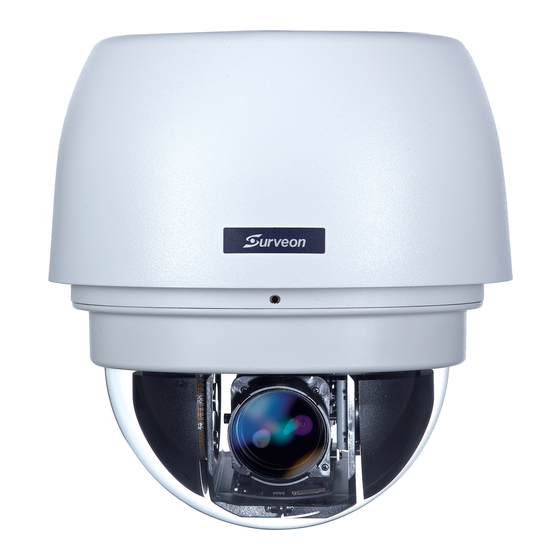
Chapter 1. Product Overview 1.1. Network Camera Introduction Speed Dome Camera series are professional network cameras that use Internet Protocol (IP) to transmit video streams and control signals over networks. Capable of operating over both LANs and WANs, they provide a complete budget-conscious remote surveillance solution that are ultra clear and highly integrated. -
Page 13: 1.2. Features And Benefits
1.2. Features and Benefits Speed Dome IP camera is a cutting-edge digital video transmission device. It can compress and transmit real-time images of outstanding quality using a reasonable amount of bandwidth through a standard TCP/IP network. The following features make this IP camera an outstanding choice when building an intelligent IP surveillance system: High Video Quality ... - Page 14 Tampering Detection This is an intelligent video analytics application available only in selected network cameras in the market. When a camera is manipulated in any way (e.g. accidental redirection, blocking, defocusing, spray-painted, covered or damaged), it can automatically trigger recording and alert notifications. Power-over-Ethernet ...
-
Page 15: 1.3. Technical Specifications
1.3. Technical Specifications CAM6181 36x Zoom Full HD D/N Outdoor Speed Dome Network Camera CAM6351 20x Zoom Full HD D/N Outdoor Speed Dome Network Camera Specifications for CAM6181 Model Name CAM6181 Description 36x Zoom Full HD D/N Outdoor Speed Dome Network Camera Image Sensor 1/4"... - Page 16 Audio Compression G711/G.726, ADPCM Audio Input / Output Line In/Out, Terminal Block Alarm In/Out 4/2 terminal block Video Buffer Send snapshot or video clip by FTP or email, record to local storage, trigger Event Action IPv4/v6, TCP/IP, UDP, RTP, RTSP, HTTP, ICMP, FTP, SMTP, DHCP, PPPoE, Supported Protocols UPnP, IGMP, SNMP, QoS, ONVIF, DDNS, NTP Ethernet...
-
Page 17: Specifications For Cam6351/6351A
Specifications for CAM6351/6351A Model Name CAM6351 CAM6351A Description 20x Zoom Full HD D/N Outdoor Speed Dome Network Camera Image Sensor 1/2.8" 2 megapixel SONY low light CMOS Lens 4.7 ~ 94 mm autofocus lens, F1.6 (wide) - F3.7 (tele) 48dB True WDR >96dB Day/Night ICR IR LED... - Page 18 Audio Input / Output Line In/Out, Terminal Block Alarm In/Out 4/2, terminal block Video Buffer Event Action Send snapshot or video clip by FTP or email, trigger DO IPv4/v6, TCP/IP, UDP, RTP, RTSP, HTTP, HTTPS, ICMP, FTP, SMTP, DHCP, Supported Protocols PPPoE, UPnP, IGMP, SNMP, QoS, IEEE 802.1X, ONVIF, DDNS, NTP Ethernet 10/100 Base-T / RJ45...
-
Page 19: Chapter 2. Hardware Overview
Chapter 2. Hardware Overview 2.1. Overview Bottom View 1. LAN Connector 2. Alarm In/Out Connector 3. Power Connector Slot 4. MicroSDHC Card Slot 5. Reset Button 6. Audio In/Out Connector... -
Page 20: 2.2. Dimensions
2.2. Dimensions Unit: mm (inches) -
Page 21: 2.3. Camera Setup
2.3. Camera Setup Preparation for Dome Camera Setup 1. Unpack the dome package and take out the dome body. 2. Remove the plastic wrapping on the dome cover. 3. Remove the Styrofoam sheet from the inside of the dome cover. 4. -
Page 22: Camera Cable Connections
7. Gently pressure the dome cover downward with two hands on the side of it. 8. Use one M3 Screw and the original two screws to screw the dome cover and camera body together. Camera Cable Connections Connecting Power Pin definitions of the power connector: Definition Color of Power Wire Connected AC 24-... - Page 23 1. Connect the power wires of AC adapter with the power connector. Please check the colors of the power wires carefully, and screw them with the connector properly. Warning: When done connecting the cables to the connector, please check for LIVE WIRES! Do not leave “LIVE WIRES”...
-
Page 24: Connecting Power With Optional Ac Adapter
Connecting Power with Optional AC Adapter Adjust the power selector according to the practical local power voltage, and connect the power cord with the adapter and power outlet. Note: Contact your dealer for purchasing the adapters. Connecting LAN Cable 1. Connect one end of the LAN cable to the LAN connector of the network Speed Dome Camera, and the other end of the cable to the network switch or PC. -
Page 25: Applying Audio (Optional)
Definition Definition ALARM_OUT_COM_2 ALARM_OUT_NO_1 ALARM_OUT_NC_1 ALARM_IN_4 ALARM_OUT_COM_1 ALARM_IN_3 ALARM_IN_2 ALARM_OUT_NO_2 ALARM_OUT_NC_2 ALARM_IN_1 Applying Audio (Optional) Set up the audio according to the audio pin definition. Definition LINE_OUT LINE_IN Inserting and the Micro SDHC Card (Optional) 1. Make sure the golden finger of the Micro SDHC card is facing downwards. 2. -
Page 26: Chapter 3. Installation
Chapter 3. Installation 3.1. Ceiling Mounting Package Contents of Ceiling Mounting Kit M8x12 Screw x1 Spring Washer-8 x1 Pendant Tube Washer x1 Rubber Washer-8 x1 Sponge x2 Items Needed Waterproof Rubber x1 (provided with the package of the camera) M5 Screw x1 (provided with the package of the camera) Screws and Screw Anchors for fixing the Straight Tube onto the ceiling (provided by users) Tools Needed... - Page 27 3. Fix the Straight Tube to the ceiling with screws and screw anchors. 4. Fit the Waterproof Rubber to the Straight Tube. (You may turn the Waterproof Rubber inside out, which is shown in the picture below, to make the fitment easier.) 5.
- Page 28 6. After threading the cables, please block the cable entry hole with the supplied sponge(s) to avoid insects entering the tube. 7. Fix the Outdoor Flange to the Straight Tube with the supplied screw (M8x12) and washers. Then adjust the Waterproof Rubber. 8.
-
Page 29: 3.2. Wall Mounting
3.2. Wall Mounting Package Contents of Wall Mounting Kit M8x12 Screw x1 Spring Washer-8 x1 Pendant Tube Washer x1 Rubber Washer-8 x1 Sponge x1 Items Needed Waterproof Rubber x1 (provided with the package of the camera) M5 Screw x1(provided with the package of the camera) Screws and Screw Anchors for fixing the Pendant onto the wall (provided by users) Tools Needed Electric Drill... - Page 30 2. Fix the Pendant on the wall with screws and screw anchors. 3. Fit the Waterproof Rubber to the Pendant. (You may turn the Waterproof Rubber inside out, which is shown in the picture below, to make the fitment easier.) 4.
- Page 31 M8x12 screw Spring washer Pendant tube washer Rubber washer 7. Mount the Dome Camera to the Outdoor Flange. Rotate the dome body and make sure the thread holes on the Lock Screw Plate and Outdoor Flange are aligned. Then screw the M5 Screw.
-
Page 32: 3.3. Camera Deployment
3.3. Camera Deployment DHCP Router Camera(s) GbE Switch SELE CT ENTER VGA Station for Local Client Smart Megapixel Video Recorder 3.4. Before You Start Please prepare a PC with Windows (XP or above) and web browsers (Internet Explorer 6.0 or above) installed. -
Page 33: Chapter 4. Connecting To The Network Camera
Chapter 4. Connecting to the Network Camera 4.1. Accessing the Camera Setting the Camera's IP The network speed Dome camera’s default IP address is: 192.168.0.250. Therefore, to access the camera for the first time, set the PC’s IP address as 192.168.0.XXX;... - Page 34 Installing Active X Components in Internet Explorer (Optional) After connecting to the camera, the request for installing the ActiveX control will appear just below the URL bar. Right Click on the information bar, and click Install ActiveX Control… to permit ActiveX control installation. In the pop-up security warning window, click Install to start downloading DC Viewer software on the PC.
-
Page 35: Chapter 5. Configuration Through Viewer Window Interface
Chapter 5. Configuration through Viewer Window Interface Overview 5.1. The Full HD Speed Dome IP Camera transmits digital video and audio data using wire connection. Live video can be monitored and recorded from window-based computer via network. The video encoder supports real-time Main Profile H.264 Full HD resolution. Simultaneous dual streams, H.264/H.264 and H.264/MJPEG, are available for various network applications via speeding or limited bandwidth. -
Page 36: Interface Layout
Interface Layout 5.2. This section demonstrates the layout of the network Speed Dome Camera’s main interface. The five setting tabs on the interface are: 1. Home: Users can monitor live video of the targeted area. 2. System: The Administrator can set host name, system time, root password, network related settings, etc. -
Page 37: 5.3. Home Page
5.3. Home Page Click on the tab Home to access the home Page. There are several function buttons on the Home pate. Detailed information of each item is as described in the following chapter. Function Items on the Home Page Multiple Languages Support Multiple languages are supported, including German, English, French, Italian, Korean, Simplified Chinese, Russian, etc. -
Page 38: Snapshot Button
Snapshot Button Click on the button and the JPEG snapshots will automatically be saved in the appointed place. The default place of saving snapshots is: C:\. To change the storage location, please refer to File Location for further details. Note: For users with Windows 7 operating system, it is required to log on as an Administrator to implement the Web Recording function. -
Page 39: Pan/Tilt Control
Manual Button Click on the Manual Button, and users can adjust focus manually via Near/Far Buttons. Near/Far Buttons Click on the Manual Button, and users can adjust focus manually via Near/Far Buttons. The status will also be displayed above the screen as shown below. Pan/Tilt Control Users can implement pan/tilt control by first moving the cursor to the live video pane;... -
Page 40: 5.4. System
5.4. System Under the System tab, there are categories as the table below: System Security Network DDNS Mail HTTP Application Motion Detection Tampering System Storage Management Recording File Location View Log File View User Information View Parameters Factory Default Software Version Software Upgrade Maintenance Note: The System Configuration page is only accessible by the Administrator. -
Page 41: System
System The System Setting can be found under the path: System > System. Host Name The name is for camera identification. If alarm function is enabled and is set to send alarm message by Mail/FTP, the host name entered here will display in the alarm message. -
Page 42: Security
Security The Security Setting can be found under this path: System > Security. Click the Security category, there will be a drop-down menu with tabs including User, HTTPS, IP Filter, and IEEE 802.1X. User The User setting can be found under this path: System > Security > User. Admin Password Change the administrator’s password by inputting the new password in both text boxes. -
Page 43: Https
Manage User Delete User To delete a user, select the user name you would like to delete from the drop-down user list and then click on the Delete Button to remove it. Edit User Select a user name from the drop-down user list and click on Edit to edit the user’s password and privilege. -
Page 44: Install Signed Certificate
Install Signed Certificate Click on the Create Certificate Request Button to create and submit a certificate request in order to obtain a signed certificate from CA. Provide the request information in the create dialog. Please refer to the following Provide the Certificate Information for more details. -
Page 45: Ip Filter
Organization Unit Enter the name of the organizational unit to which the entity identified in Common Name belongs. Common Name Indicate the name of the person or other entity that the certificate identifies (often used to identify the website). Valid days Enter the period in days (1~9999) to indicate the valid period of certificate. -
Page 46: Ieee 802.1X
IEEE 802.1X The IEEE 802.1X setting can be found under this path: System > Security > IEEE 802.1X. The IP Camera is allowed to access a network protected by 802.1X/EAPOL (Extensible Authentication Protocol over LAN). Users need to contact with the network administrator for gaining certificates, user IDs and passwords CA Certificate The CA certificate is created by the Certification Authority for the purpose of... -
Page 47: Network
Network The Network setting can be found under this path: System > Network. Click on the Network category, there will be a drop-down menu with tabs including Basic, QoS, SNMP, and UPnP. Basic The Basic setting can be found under this path: System > Network > Basic. Users can choose to connect to the IP Camera with fixed or dynamic (DHCP) IP address. - Page 48 This is the gateway used to forward frames to destinations in different subnet. Invalid gateway setting will fail the transmission to destinations in different subnet. Primary DNS Primary DNS is the primary domain name server that translates hostnames into IP addresses. Secondary DNS ...
-
Page 49: Qos
IPv6 Address Configuration With IPv6 support, users can use the corresponding IPv6 address for browsing. Enable IPv6 by checking the box and click on Save to complete the setting. The QoS (Quality of Service) setting can be found under this path: System > Network >... -
Page 50: Snmp
SNMP The SNMP (Simple Network Management Protocol) setting can be found under this path: System > Network > SNMP. With Simple Network Management Protocol (SNMP) support, the IP Camera can be monitored and managed remotely by the network management system. SNMP v1/ v2 Enable SNMP v1/ v2 Select the version of SNMP to use by checking the box. -
Page 51: Upnp
Trap Option Warm Start A Warm Start SNMP trap signifies that the SNMP device, i.e. IP Camera, performs software reload. Click on Save Button when complete. UPnP The UPnP setting can be found under this path: System > Network > UPnP. UPnP Setting Enable UPnP When the UPnP is enabled, whenever the IP Camera is presented to the LAN, the... -
Page 52: Ddns
DDNS The DDNS setting can be found under this path: System > DDNS. Dynamic Domain Name System (DDNS) allows a host name to be constantly synchronized with a dynamic IP address. In other words, it allows those using a dynamic IP address to be associated to a static domain name so others can connect to it by name. -
Page 53: Ftp
The FTP setting can be found under this path: System > FTP. The Administrator can set as sending alarm message to a specific File Transfer Protocol (FTP) site when an alarm is triggered. Users can assign alarm message to up to two FTP sites. -
Page 54: Alarm Setting
Alarm Setting Alarm Switch The Administrator can enable or disable the alarm function. Alarm Type Select an alarm type, Normal Close or Normal Open, that corresponds with the alarm application. Triggered Action (Multi-option) The Administrator can specify alarm actions that will take at an alarm occurrence. All options are listed as follows: Enable Alarm Output 1/2 Select these items to enable alarm relay outputs. - Page 55 PTZ Function Assign a camera function: Preset, Sequence, Autopan or Cruise, and specify a Preset Point/Sequence Line/Autopan Path/Cruise Line for the camera to perform at an alarm occurrence. Note: Please refer to the sections through Preset to Sequence for details of Preset Point/Cruise Line/Autopan Path/Sequence Line setups.
- Page 56 Note: Please make sure the local recording (with Micro SD/ SDHC card) is activated so that this function can be implemented. Refer to Recording for further details. File Name Enter a file name in the File name field, ex. image.jpg. The uploaded image’s file name format can be set in this section.
-
Page 57: Motion Detection
Motion Detection The Motion Detection setting can be found under this path: System > Motion Detection. Motion Detection function allows detecting suspicious motion and triggering alarms when motion volume in the detected area reaches/exceeds the determined sensitivity threshold value. In the Motion Detection setting page, there is a frame (Motion Detection Window) displayed on the Live Video Pane. -
Page 58: Motion Detection
Motion Detection Users are able to turn on/off Motion Detection. Default setting is Off. Motion Detection Setting Users could adjust various parameters of Motion Detection in this section. Sampling Pixel Interval [1-10] The default value is 1, which means system will take one sampling pixel for every pixel. -
Page 59: File Name
Upload Image by FTP Select this item and the Administrator can assign a FTP site and configure various parameters. When motion is detected, event images will be uploaded to the appointed FTP site. Upload Image by E-Mail Select this item and the Administrator can assign an e-mail address and configure various parameters. -
Page 60: Tampering
Tampering The Tampering setting can be found under this path: System > Tampering. Tempering Alarm function helps the IP Camera against tampering such as deliberate redirection, blocking, paint spray, and lens cover, etc through video analysis and reaction to such events by sending out notifications or uploading snapshots to the specified destination(s). -
Page 61: File Name
Send Alarm Message by FTP/E-Mail The Administrator can select whether to send an alarm message by FTP and/or E-Mail when tampering is detected. Upload Image by FTP Select this item and the Administrator can assign a FTP site and configure various parameters. -
Page 62: Storage Management (Local Recording)
Storage Management (Local Recording) The Storage Management setting can be found under this path: System > Storage Management. Users can implement local recording to the Micro SD/SDHC card up to 32GB. This page shows the capacity information of the Micro SD card and a recording list with all the recording files saved on the memory card. -
Page 63: Recording (Local Recording)
memory card. Then the IP Camera will return to the regular recording mode after events recording. Remove To remove a file, select the file first, and then click on the Remove Button. Sort Click on the Sort Button, and the files in the recording list will be listed in name and date order. -
Page 64: Terminating Micro Sd/Sdhc Card Recording
Terminating Micro SD/SDHC Card Recording Select Disable to terminate the recording function. File Location (Snapshots and Web Recording) The Snapshot setting can be found under this path: System > Snapshot. Users can specify a storage location on the PC or in the hard drive for the snapshots and live video recording. -
Page 65: View Parameters
Therefore, it denotes the user is granted privileges of I/O access, Camera control and Listen. View Parameters The View Parameters function can be found under this path: System > View Parameter. Click on this item to view the entire system’s parameter setting. Factory Default The Factory Default setting can be found under this path: System >... -
Page 66: Maintenance
1. Click on Browse and select the binary file to be uploaded, ex. userland.img. Note: Do not change the upgrade file name, or the system will fail to find the file. 2. Pull down the upgrade binary file list and select the file you want to upgrade;... -
Page 67: 5.5. Streaming
5.5. Streaming Under the Streaming tab, there are categories including: Video Format, Video Compression, Video OCX Protocol, Video Frame Rate, and Audio. In Streaming, the Administrator can configure specific video resolution, video compression mode, video protocol, audio transmission mode, etc. Further details of these settings will be specified in the following sections. - Page 68 MJPEG+ H.264 H.264 MJPEG BNC SUPPORT 720 x 480 (30fps)* √ 1920 x 1080 (30fps) 640 x 480 (30fps) √ 352 x 240 (30fps) √ 1920 x 1080 (15fps) √ 1280 x 1024 (30fps) √ 1920 x 1080 (15fps) 1280 x 720 (30fps) √...
- Page 69 H.264 + H.264 H.264-1 H.264-2 BNC SUPPORT 720 x 480 (30fps)* √ 1920 x 1080 (30fps) 640 x 480 (30fps) √ 352 x 240 (30fps) √ 1920 x 1080 (15fps) √ 1280 x 1024 (30fps) √ 1920 x 1080 (15fps) 1280 x 720 (30fps) √...
-
Page 70: Text Overlay Settings
MJPEG ONLY MJPEG BNC SUPPORT 1920 x 1080 (30fps) √ 1280 x 1024 (30fps) √ 1280 x 720 (30fps) √ 1024 x 768 (30fps) √ 800 x 600 (30fps) √ 720 x 480 (30fps) √ 640 x 480 (30fps) √ H.264 ONLY H.264 BNC SUPPORT... -
Page 71: Video Rotate Type
Video Rotate Type Users can change video display type if necessary. Selectable video rotate types include Normal, Flip, Mirror, 90 degree clockwise, 180 degree rotate and 90 degree counterclockwise. Differences among these types are illustrated as below. Suppose the displayed image of the IP Camera is shown as the figure below. To rotate the image, users can select Flip, for instance. -
Page 72: Gov Settings
180 Degree Rotate Selecting 180 Degree will make the image 180°inversed. Click on Save to confirm the setting. GOV Settings Users can set the GOV length to determine the frame structure (I-frames and P-frames) in a video stream for saving bandwidth. Longer GOV means decreasing the frequency of I-frames. -
Page 73: Video Ocx Protocol
Video OCX Protocol The Video OCX Protocol setting can be found under this path: Streaming > Video OCX Protocol. In the Video OCX protocol setting page, users can select RTP over UDP, RTP over TCP, RTSP over HTTP or MJPEG over HTTP, for streaming media over the network. In the case of multicast networking, users can select the Multicast mode. -
Page 74: Server Gain Setting
In the Full-duplex mode, the local and remote sites can communicate with each other simultaneously, i.e. both sites can speak and be heard at the same time. Half-duplex (Talk or Listen, Not at the Same Time) In the Half-duplex mode, the local/remote site can only talk or listen to the other site at a time. -
Page 75: 5.6. Ptz
5.6. PTZ Under the PTZ tab, there are categories including: Preset, Cruise, Auto Pan, Sequence, Home, Tilt Range, Camera- Exposure, Camera- WB, Camera- Misc1, Camera- Misc2, and Camera- Default. Preset The Preset Programming can be found under this path: PTZ > Preset. Totally 256 Preset Points can be programmed for the IP Camera. -
Page 76: Cruise Run
programming, click on the Set Button of Record End to quit. Then this Cruise Path will be automatically recorded. Cruise Run Select the specified Cruise Path from the drop-down list, click on the Run Button, and then the camera will start touring around as recorded. To view the camera touring around in full screen mode, please move the cursor onto the live view pane, right-click and left-click to select Full Screen. -
Page 77: Sequence
To view the camera panning in full screen mode, please move the cursor onto the live view pane, right-click and left-click to select Full Screen. Then users can view the camera navigation in full screen. To stop running an Auto Pan Path, simply move the cursor to the live view pane and move the camera in any direction. -
Page 78: Home
To view the camera executing a Sequence Line in full screen mode, please move the cursor onto the live view pane, right-click and left-click to select Full Screen. Then users can view the camera navigation in full screen. To stop running the Sequence Line, simply move the cursor to the live view pane and move the camera in any direction. -
Page 79: Tilt Range
Tilt Range The Tilt Range Setting can be found under this path: PTZ > Tilt Range. The IP Camera’s tilt angle is adjustable from minimum -10° to maximum 190°. Please enter the desired minimum and maximum tilt angle into the corresponding fields respectively. -
Page 80: Manual Mode
Manual Mode In this mode, users can change the Shutter speed (1/10000 to 1), Iris (F1.6 to F28), and Gain (1 to 15) manually. Camera - WB (White Balance) The White Balance Setting can be found under this path: PTZ > Camera - WB. A camera needs to find reference color temperature, which is a way of measuring the quality of a light source, for calculating all the other colors. -
Page 81: Camera - Misc 1 (Miscellaneous Setups Menu 1)
Camera - Misc 1 (Miscellaneous Setups Menu 1) The Miscellaneous Setting Menu 1 can be found under this path: PTZ > Camera- Misc In the Camera—Misc (Miscellaneous) Setups Menu 1, users can set various camera parameters including Backlight Compensation (BLC), Sharpness, Exposures Compensation (ExpComp), Image Flip, Speed by Zoom and ICR function. -
Page 82: Speed By Zoom
Speed by Zoom Enable this function to adjust the pan/tilt speed automatically by internal algorithm when zooming. The larger zoom ratio leads to the lower rotating speed. Click on the Set Button to save the setting. ICR Function With the IR cut filter, the camera can still catch clear image at night time or in low light conditions. -
Page 83: 2Dnr
2DNR With the 2D Noise Reduction function, the processor analyzes pixel by pixel and frame by frame to eliminate environmental noise signal so that the highest quality image can be produced even in low light conditions. Click on the Set Button to save the setting. -
Page 84: 5.7. Logout
5.7. Logout Click on the Logout tab on the top of the page, and the login window will pop up. This enables login with another user name. 5.8. Appendix Appendix A: Install UPnP Components Please follow the instructions below to install UPnP components. 1. -
Page 85: Appendix B: Deleting The Existing Dc Viewer
Appendix B: Deleting the Existing DC Viewer For users who have installed the DC Viewer in the PC previously, please first remove the existing DC Viewer from the PC before accessing to the network Speed Dome Camera. Deleting the DC Viewer Activate Control Panel, and then double click on Add or Remove Programs. -
Page 86: Appendix C: Setup Internet Security
Appendix C: Setup Internet Security If ActiveX control installation is blocked, please either set Internet security level to default or change ActiveX controls and plug-ins settings. Internet Security Level: Default 1. Start the Internet Explorer (IE). 2. Click on the Tools tab on the menu bar and select <Internet Options>. 3. - Page 87 Close the browser window, and restart a new one later for accessing the camera.
Need help?
Do you have a question about the Speed Dome IP Camera Series and is the answer not in the manual?
Questions and answers