
Related Manuals for Nilfisk-Advance R 253 9087362020


Summary of Contents for Nilfisk-Advance R 253 9087362020
-
Page 1: Service Manual
SCRUBTEC R 253 - RA40 Service Manual Nilfisk R 253, 9087362020 - 9087365020 Clarke RA40, 9087363020 English 01/2015 revised 03/2016 (2) Form No. 9100000402... -
Page 2: Table Of Contents
Service Manual – Scrubtec R 253 - RA40 Contents Contents General Information Machine General Description Service Manual Purpose and Field of Application Other Reference Manuals Conventions Service and Spare Parts Serial Number Label Safety Visible Symbols on the Machine Symbols General Instructions Machine Lifting Machine Transportation... - Page 3 Service Manual – Scrubtec R 253 - RA40 Contents Electrical System Functional Description Battery Charger Battery Charge State Display Wiring Diagram Component Locations Maintenance and Adjustments Setting the Installed Battery Type Battery installation Battery Charging Checking/Replacing Fuses Troubleshooting Specifications Wiring Diagram Options and Accessories Recovery System Functional Description...
- Page 4 Service Manual – Scrubtec R 253 - RA40 Contents Solution System Functional Description Water Level Sensor Operation Wiring Diagram Component Locations Maintenance and Adjustments Cleaning the Solution Tank and Filter Cleaning the Chemical Mixing System Detergent Tank Draining the Chemical Mixing System Troubleshooting Checking the Water Level Sensor Operation Removal and Installation...
-
Page 5: General Information
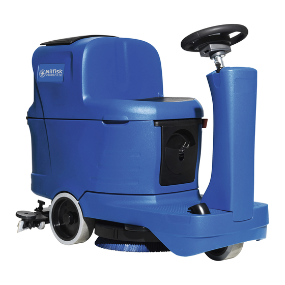
Service Manual – Scrubtec R 253 - RA40 General Information General Information Machine General Description The Scrubtec R 253 and Clarke RA40 are a “man on-board” industrial machine designed to wash and dry floors in one pass The machine is powered by on-board batteries, models can be equipped with chemical mixing sys- tem. -
Page 6: Conventions
Battery 24 Vdc Type E SCRUBBER DRYER Control Nr: UL 583 3084826 CSA C22.2 N.68-92 “Made in Hungary” 14600 21st Ave N Plymouth, MN, USA www.clarkeus.com A Nilfisk-Advance Brand Figure 1 MACHINE model ..................... PRODUCT code ....................MACHINE serial number ................. -
Page 7: Safety
Service Manual – Scrubtec R 253 - RA40 General Information Safety The following symbols indicate potentially dangerous situations Always read this information carefully and take all necessary precautions to safeguard people and property Visible Symbols on the Machine Warning! Carefully read all the instructions before performing any operation on the machine. -
Page 8: General Instructions
Service Manual – Scrubtec R 253 - RA40 General Information General Instructions Specific warnings and cautions to inform about potential damages to people and machine are shown below. Warning! Make sure to follow the safety precautions to avoid situations that may lead to serious injuries. - Page 9 Service Manual – Scrubtec R 253 - RA40 General Information • Check the machine carefully before each use, always check that all the components have been properly assembled before use If the machine is not perfectly assembled it can cause damages to people and prop- erties •...
-
Page 10: Machine Lifting
Service Manual – Scrubtec R 253 - RA40 General Information Machine Lifting Warning! Do not work under the lifted machine without supporting it with safety stands. Machine Transportation Warning! Before transporting the machine, make sure that: All covers are closed. The recovery tank and the detergent tank are empty. -
Page 11: Machine Nomenclature (Know Your Machine)
Service Manual – Scrubtec R 253 - RA40 General Information Machine Nomenclature (know your machine) Seat EMERGENCY Battery connector Recovery tank Squeegee hook push-button cover Steering wheel with control panel Dumping recovery tank assembly Can holder Solution tank Battery charger cable Solution drain and level check hose... - Page 12 Service Manual – Scrubtec R 253 - RA40 General Information Machine Nomenclature (Continues) Electronic Chemical mix- Batteries Tank assembly sup- component ing system port rod compartment detergent tank cover Lifted recovery tank assembly and driver’s seat Recovery water tank cover (open) Vacuum grid with auto- matic shut-off float Container with debris col-...
-
Page 13: Control Panel
Service Manual – Scrubtec R 253 - RA40 General Information Control Panel Multifunction display and operating information Machine ignition key Horn button Reverse gear button Detergent percentage One-Touch Scrub ON/ adjustment button OFF push-button Vacuum system Solution flow button adjustment button Figure 4... -
Page 14: Service And Diagnostic Equipment
Service Manual – Scrubtec R 253 - RA40 General Information Service and Diagnostic Equipment Besides a complete set of standard meters, the following instruments are necessary to perform fast checks and repairs on Nilfisk Clarke machines: • Laptop computer charged with the current version of EzParts, Adobe Reader and (if possible) Internet connection •... -
Page 15: Technical Data
Service Manual – Scrubtec R 253 - RA40 General Information Technical Data Nilfisk Nilfisk Description / Model Scubtec R253 full PKG Scubtec R253 Clarke RA40 Solution tank capacity 18,5 US gal (70 liters) Recovery tank capacity 18,5 US gal (70 liters) Machine length 50 in (1270 mm) Machine width with squeegee... -
Page 16: Dimensions
Service Manual – Scrubtec R 253 - RA40 General Information Dimensions 28.3 in (720 mm) 50.0 in (1270 mm) Figure 6... -
Page 17: Scheduled Maintenance Table
Service Manual – Scrubtec R 253 - RA40 General Information Maintenance The lifespan of the machine and its maximum operating safety are ensured by correct and regular maintenance. Warning! Read carefully the instructions in the Safety chapter before performing any maintenance procedure. -
Page 18: Chassis System
Service Manual – Scrubtec R 253 - RA40 Chassis System Chassis System Frame (main parts) Reference to Figure 1 • Steering assembly/column support plate and deck mount • Main support side member • Gearmotor support plate and squeegee system mount Steering assembly/column support plate and deck mount Gearmotor support plate and... -
Page 19: Control System
Service Manual – Scrubtec R 253 - RA40 Control System Control System Functional Description The architecture of the electronic control system for The display electronic board (EB2) the machine’s electrical components is composed of a function electronic board (EB1) and a display elec- Flat cable from (EB2) to (EB4) tronic board (EB2), in turn connected to a dashboard instrument electronic board (EB4) which represents... -
Page 20: Wiring Diagram
Service Manual – Scrubtec R 253 - RA40 Control System Wiring Diagram Electronic board power supply + Key electronic board power supply + J1.1 Return from USER key J1.2 SIGNAL CIRCUIT Key reader power supply circuit J1.3 (+5V) FUSE (F2) Key Identification J1.4 IGNITION KEY (SW1) -
Page 21: Component Locations
Service Manual – Scrubtec R 253 - RA40 Control System Component Locations • Function electronic board (EB1) • Flat cables from (EB2) to (EB4) • Display electronic board (EB2) • Ignition Key (SW1) • Dashboard instrument electronic board (EB4) Function electronic board (EB1) Figure 2 Flat cables from (EB2) to (EB4) -
Page 22: Troubleshooting
Service Manual – Scrubtec R 253 - RA40 Control System Troubleshooting Function Electronic Board (EB1) Alarm Codes The function electronic board indicates a series of alarms in case of malfunction of one or more systems, and in case of abnormal conditions detected in the input signals The alarms are shown on the display in the following format (Figure 4) Figure 4 In case the display is malfunctioning, the alarms are also repeated by the yellow and red diagnostic LEDs... - Page 23 Service Manual – Scrubtec R 253 - RA40 Control System Function Electronic Board (EB1) Alarm Codes (Continues) General alarms Alarm on function electronic board - FLASHING YELLOW + RED LEDS Alarm code -------------------------- Meaning Condition Effect Service Suggestions Flashes Description Blown F1 fuse.
- Page 24 Service Manual – Scrubtec R 253 - RA40 Control System Function Electronic Board (EB1) Alarm Codes (Continues) Function electronic board alarms Alarm on function electronic board - FLASHING RED LED Alarm code flashes on -------------------------- Meaning Condition Effect Service Suggestions electronic Description board...
- Page 25 Service Manual – Scrubtec R 253 - RA40 Control System Function Electronic Board (EB1) Alarm Codes (Continues) Drive system alarms Alarm on function electronic board - FLASHING YELLOW LED Alarm code flashes on -------------------------- Meaning Condition Effect Service Suggestions electronic Description board Amperometric...
- Page 26 Service Manual – Scrubtec R 253 - RA40 Control System Function Electronic Board (EB1) Alarm Codes (Continues) On-board Battery Charger Alarms Alarm code -------------------------- Meaning Condition Effect Service Suggestions Description Communication No signal from battery The battery charger Check the wiring between the battery charger ----------------------- problem charger via gate J4.4 for...
-
Page 27: Super User Screen
Service Manual – Scrubtec R 253 - RA40 Control System Super User Screen The alarms activated during normal machine operation are stored and can be read in the corresponding log (Alarm Log Screen) Alarm Log Screen The alarms log screen (F, Figure 6) function allows you to check any alarms stored on the machine Turn the ignition key to “I”... - Page 28 Service Manual – Scrubtec R 253 - RA40 Control System Alarm Log Screen (continues) Improper uses of the batteries or battery charger are also recorded, as in the following table: On-board Battery Charger Alarms Alarm code -------------------------- Meaning Condition Effect Description GB-N Time of...
-
Page 29: Setting Screen
Service Manual – Scrubtec R 253 - RA40 Control System Setting Screen The machine function parameters screen (C, Figure 7) allows you to customise some parameters described in the following table of modifiable parameters. Turn the ignition key to “I” holding down both the horn button (A) together with the adjustment percentage detergent button (B) Press the One-Touch button (D) to increase the value of the current parameter Press the vacuum system button (E) to decrease the value of the current parameter... - Page 30 Service Manual – Scrubtec R 253 - RA40 Control System Setting Screen (Continues) The following parameters are displayed only when, on reaching the last RESET parameter, the reverse but- is pressed together with the detergent percentage adjustment button and the solution flow adjustment button Otherwise at the reverse button pressed, the system will return to the first parameter P1/P3...
-
Page 31: Hours Screen
Service Manual – Scrubtec R 253 - RA40 Control System Hours Screen Turn the ignition key to “I” holding down both the horn button (A, Figure 8) together with the adjustment percentage detergent button (B) Press hold 1 second the reverse button (C) to switch to the screen menu (D) Press the horn button (A) to access the operating time counter screen (E) The operating time counter screen (E) function allows you to check the total accumulated hours of work for each machine subsystem:... -
Page 32: System For Flow Rate Adjustment As Function Of Speed
Service Manual – Scrubtec R 253 - RA40 Control System System for Flow Rate Adjustment as Function of Speed Solution flow levels 1, 2 and 3 regulate the flow of solution on the basis of the machine speed so as to keep the quantity of solution dispensed per square metre of floor treated constant. -
Page 33: Removal And Installation
Service Manual – Scrubtec R 253 - RA40 Control System Removal and Installation Function Electronic Board (EB1) Removal/Replacement Drive the machine on a level floor and remove the operator key. Disconnect the red battery connector by pressing the emergency push-button Lift the recovery tank assembly and the driver’s seat Remove the 3 screws and remove the upper cover Remove the 2 screws and remove the function electronic board front cover... - Page 34 Service Manual – Scrubtec R 253 - RA40 Control System Function Electronic Board (EB1) Removal/Replacement (Continues) Disconnect the following connections (Figure 11): ◦ (I) Key, accelerator and steering wheel electronic board connection (J1) ◦ (J) Squeegee actuator, beacon light and driver’s seat sensor connection (J3) ◦...
-
Page 35: Display Board (Eb2) And Dashboard Instrument Board (Eb4) Removal/Replacement
Service Manual – Scrubtec R 253 - RA40 Control System Display Board (EB2) and Dashboard Instrument Board (EB4) Removal/Replacement Display Board (EB2) Drive the machine on a level floor. Lift the cover of the dashboard instrument board (D, Figure 15) and recover the gasket (E) Remove the operator key and disconnect the red battery connector Remove the screws (F) and remove the display... - Page 36 Service Manual – Scrubtec R 253 - RA40 Control System Display Board (EB2) and Dashboard Instrument Board (EB4) Removal/Replacement (Continues) Dashboard Instrument Board (EB4) 10 Perform points 1 to 6 for removal of the display Assembly electronic board (EB2) 13 Assemble the components in the reverse order of disassembly and note the following: 11 Disconnect the flat connections (K, Figure 17) and (L) from the display electronic board (EB2)
-
Page 37: Specifications
Service Manual – Scrubtec R 253 - RA40 Control System Specifications Function Electronic Board (EB1) Connectors (Figure 19) Power connections (Ø6mm male RADSOK terminals - AMPHENOL SK 200800532 101 or equivalent) Electronic board Ref. Description V ref. I max. Connected to in/out Electronic board power supply + 125A... - Page 38 Service Manual – Scrubtec R 253 - RA40 Control System Function Electronic Board (EB1) Connectors (Continues) (Figure 21) Drive connections (Ø3.6mm male RADSOK terminals - AMPHENOL P/N N01 036 6501 001 or equivalent) Electronic board Ref. Description V ref. I max. Connected to in/out Drive system motor +...
- Page 39 Service Manual – Scrubtec R 253 - RA40 Control System Function Electronic Board (EB1) Connectors (Continues) (Figure 23) J1: MOLEX MINIFIT type, 12-ways vertical Description Electronic board V ref. I max. Connected to in/out Key electronic board power supply + Return from USER key Key reader power supply circuit <1A...
- Page 40 Service Manual – Scrubtec R 253 - RA40 Control System Function Electronic Board (EB1) Connectors (Continues) (Figure 25) J3: MOLEX MINIFIT type, 6-ways vertical Description Electronic board V ref. I max. Connected to in/out Squeegee actuator power supply +/- 0/24V Driver’s seat microswitch power supply <1A Auxiliary power supply -...
- Page 41 Service Manual – Scrubtec R 253 - RA40 Control System Function Electronic Board (EB1) Connectors (Continues) (Figure 27) J5: JST VHR-3N type, 3-way vertical Description Electronic board V ref. I max. Connected to in/out Power supply for water level sensor + <1A S1.1 Water level sensor return...
- Page 42 Service Manual – Scrubtec R 253 - RA40 Control System Function Electronic Board (EB1) Connectors (Continues) (Figure 29) J7: TYCO MODU II type, 6-ways vertical Description Electronic board V ref. I max. Connected to in/out +24V power supply <1A TRK.RD +5V power supply <1A iButton input...
-
Page 43: Display Electronic Board (Eb2) Connectors
Service Manual – Scrubtec R 253 - RA40 Control System Display Electronic Board (EB2) Connectors (Figure 31) J1: MOLEX MINIFIT type, 6-ways vertical Electronic Ref. Description V ref. I max. Connected to board in/out Power supply + CFG2.J1.6 Machine startup enabling CFG2.J1.7 Display electronic board serial + in/out... -
Page 44: Shop Measurements
Service Manual – Scrubtec R 253 - RA40 Control System Shop Measurements The following tables contain some “real world” shop voltage measurements to help you recognize what “nor- mal” looks like. All voltage values were measured with the black (Negative) voltmeter lead connected to the main battery negative unless otherwise specified. - Page 45 Service Manual – Scrubtec R 253 - RA40 Control System Shop Measurements - Function Electronic Board (EB1) (continues) Drive System Motor Figure 34 Specify if with operator on board or drive motor without load (machine lifted) The values seem a little bit low Color Description Measured...
- Page 46 Service Manual – Scrubtec R 253 - RA40 Control System Shop Measurements - Function Electronic Board (EB1) (continues) J1 - 12 Ways Figure 36 Color Circuit Description Measured Comments Key electronic board power supply + 24.4V Off or On Orange Return from USER key 0.02V Key not in slot...
- Page 47 Service Manual – Scrubtec R 253 - RA40 Control System Shop Measurements - Function Electronic Board (EB1) (continues) J2 - 2 Ways Figure 37 Color Circuit Description Measured Comments Black 2 Deck actuator power supply +/- 24.4V At rest 0.04V Extending (deck down) 24.3v Retracting (deck up)
- Page 48 Service Manual – Scrubtec R 253 - RA40 Control System Shop Measurements - Function Electronic Board (EB1) (continues) J4 - 4 Ways Figure 39 Color Circuit Description Measured Comments White Enabling from battery charger 24.4V Not Charging 0.013V Charging Yellow Power supply from battery charger 0.032V Not Charging...
- Page 49 Service Manual – Scrubtec R 253 - RA40 Control System Shop Measurements - Function Electronic Board (EB1) (continues) J6 - 2 Ways Figure 41 Two way vertical jumper • What is this for? The J6 Jumper is used to configure the function board for the EcoFlex option. •...
- Page 50 Service Manual – Scrubtec R 253 - RA40 Control System Shop Measurements - Function Board (EB1) (continues) J8 - 10 Ways Figure 43 Color Circuit Description Measured Comments Blue Solenoid valve power supply - 24.2V When off 0.08v When on (momentary) Black Detergent pump power supply - 24.2V...
-
Page 51: Shop Measurements - Display Electronic Board (Eb2)
Service Manual – Scrubtec R 253 - RA40 Control System Shop Measurements - Display Electronic Board (EB2) Measure and record the voltage at each of the function board pins Always use battery negative as your refer- ence point for your black voltmeter lead J1 - 6 Ways REAR Figure 44... - Page 52 Service Manual – Scrubtec R 253 - RA40 Control System Shop Measurements - Display Electronic Board (EB2) (continues) J2 12 way ribbon connector FRONT Figure 45 Color Circuit Description Measured Comments Power supply - common 0.007V HORN button (P3) 3.1V Not pressed 0.03V Pressed...
- Page 53 Service Manual – Scrubtec R 253 - RA40 Control System Shop Measurements - Display Electronic Board (EB2) (continues) J3 6 way ribbon connector FRONT Figure 46 Color Circuit Description Measured Comments Power supply – common 0.007V BRUSH RELEASE function LED 0.01V (LD3) 0.9V...
-
Page 54: Electrical System
Service Manual – Scrubtec R 253 - RA40 Electrical System Electrical System Functional Description The batteries (2 x 12V) are connected together in se- The green cable (terminal 4 of connector C3) is the ries by the cables data cable between electronic board (EB1) and bat- The battery charger (CH) is connected to the machine tery charger (CH) by two connectors (C) (power connection to the batter-... -
Page 55: Wiring Diagram
Service Manual – Scrubtec R 253 - RA40 Electrical System Wiring Diagram MAIN BATTERY BATTERY CONNECTOR CONNECTOR J4.1 J4.1 Enabling from battery charger SIGNAL CIRCUIT C2.A FUSE (F2) 24V BATTERIES (**) J4.2 Power supply from battery charger (BAT) J4.3 J4.3 Battery charger enabling power supply J4.4 Battery charger data communication... -
Page 56: Component Locations
Service Manual – Scrubtec R 253 - RA40 Electrical System Component Locations • Function electronic board (EB1) • Signal circuit fuse (F2) • Function electronic board fuse (F1) • Battery charger (CH) • Battery connections • Batteries (BAT) • Battery connector (C1) Batteries (BAT) Battery connections Battery connector (C1) - Page 57 Service Manual – Scrubtec R 253 - RA40 Electrical System Component Locations (continues) • On board battery charger connector (C2) • J4 Bridge for without or broken on board battery charger On board battery charger connector (C2) Figure 4 J4 bridge connector for without or broken on board battery charger Figure 5...
-
Page 58: Maintenance And Adjustments
Service Manual – Scrubtec R 253 - RA40 Electrical System Maintenance and Adjustments Setting the Installed Battery Type Set the machine and the on-board battery charger (where fitted) on the basis of the type of battery to be in- stalled by modifying the BAT parameter as shown Turn the ignition key to “I”... - Page 59 Service Manual – Scrubtec R 253 - RA40 Electrical System Battery Charging (Continues) Warning! When using lead (WET) batteries, battery charging produces highly explosive hydrogen gas. Charge the batteries in well-ventilated areas and away from naked flames. Do not smoke while charging the batteries. Keep the recovery tank lifted until the battery charging cycle is over.
-
Page 60: Battery Installation
Service Manual – Scrubtec R 253 - RA40 Electrical System Battery installation Remove the operator key Disconnect the battery connector by pressing the emergency push-button Lift the recovery tank cover and check that it is empty; if not, empty it using the drain hose Grasp the handle and carefully lift the recovery tank assembly and the driver’s seat The machine is supplied with cables suitable to install 2 12V batteries Carefully lift the batteries until the relevant compartment, then place them properly... -
Page 61: Checking/Replacing Fuses
Service Manual – Scrubtec R 253 - RA40 Electrical System Checking/Replacing Fuses Drive the machine on a level floor and remove the operator key. Disconnect the red battery connector by pressing the emergency push-button Lift the recovery tank Remove the 3 screws and remove the upper cover Remove the 2 screws and remove the electronic board front cover Check/replace the following fuses (Figure 8): ◦... -
Page 62: Troubleshooting
Service Manual – Scrubtec R 253 - RA40 Electrical System Troubleshooting See the other chapters for previously provided instructions for other electrical system components Trouble Possible Causes Remedy The machine is not working Batteries (BAT) flat or connections faulty Charge the battery or clean the connections The batteries (BAT) are broken Check the battery no-load voltage... -
Page 63: Specifications
Service Manual – Scrubtec R 253 - RA40 Electrical System Specifications Nilfisk Nilfisk Description / Model Scubtec R253 full PKG Scubtec R253 Clarke RA40 Battery compartment size (length x width x height) 13.7x14.1x11 in (350x360x280 mm) Standard batteries (2) Discover 12V-105Ah Standard battery run time (capacity) 2.5 h Input voltage... -
Page 64: Wiring Diagram
Service Manual – Scrubtec R 253 - RA40 Electrical System Wiring Diagram FUNCTION ELECTRONIC BOARD (EB1) USB PORT 5V POWER UNIT (EB5) BATTERY CONNECTOR (C1) (USB) Electronic board power supply + J8.4 Opt power supply - BRUSH Brush motor + MOTOR (M1) J8.9 Opt power supply +... -
Page 65: Options And Accessories
Service Manual – Scrubtec R 253 - RA40 Options and Accessories Options and Accessories Description Illustration CHEMICAL MIXING SYSTEM KIT (EU model only) Insert-dry brake Refill cap Hose Pump chemical mix Sensor water level Support sensor Hardware BATTERY CHARGER KIT (EU model only) Charger extention UK / EU Cable tie plug... - Page 66 Service Manual – Scrubtec R 253 - RA40 Options and Accessories Description Illustration BROOM HOLDER KIT (EU model only) Support mop Spacer for support Tool holder Hardware ENHANCED VACUUM SYSTEM MOTOR KIT (EU model only) Vacuum motor assembly Hardware WATER FILLER HOSE KIT Support rubber for filling hose Hose filling Hardware...
- Page 67 Service Manual – Scrubtec R 253 - RA40 Options and Accessories Description Illustration STOP WATER KIT Solution cap Fitting quick 1/2 gas Valve water stop Support Hardware BEACON LIGHT KIT Support Beacon Hardware USB KIT USB cable Plate Hardware...
- Page 68 Service Manual – Scrubtec R 253 - RA40 Options and Accessories Description Illustration TRACKCLEAN KIT Trackclean sensor assy Mounting cradle Trackclean system (IButton) Trackclean reader kit (reader, 2 keys) Trackclean system RDR...
-
Page 69: Recovery System
Service Manual – Scrubtec R 253 - RA40 Recovery System Recovery System Functional Description The recovery system removes the dirty water from When the automatic float closes and shuts down the the floor and pipes it to a recovery tank. When the vacuum system, the vacuum system motor noise will machine is running, the dirty water on the floor is col- increase and the floor will not be dried. -
Page 70: Component Locations
Service Manual – Scrubtec R 253 - RA40 Recovery System Component Locations • Recovery tank • Vacuum system motor (M2) • Recovery tank cover • Container with debris collection grid • Cover gasket • Vacuum grid with automatic shut-off float •... -
Page 71: Maintenance And Adjustments
Service Manual – Scrubtec R 253 - RA40 Recovery System Maintenance and Adjustments Recovery Tank Cleaning Drive the machine to the appointed disposal Note: The gasket (E) creates the area vacuum in the tank that is necessary to vacuum up the Drain the water from the tank using the drain recovery water. -
Page 72: Troubleshooting
Service Manual – Scrubtec R 253 - RA40 Recovery System Troubleshooting Trouble Possible Causes Remedy The vacuum system motor will not turn Wiring between function electronic board (EB1) and Repair vacuum system motor (M2) damaged Dashboard instrument electronic board (EB4) faulty Replace Vacuum system motor faulty Check the amperage... -
Page 73: Vacuum System Motor Amperage Test
Service Manual – Scrubtec R 253 - RA40 Recovery System Vacuum System Motor Amperage Test Warning! This procedure must be performed by qualified personnel only. Lift the recovery tank assembly and the driver’s seat Apply the amp clamp (A) to a cable (B) near the vacuum unit (Figure 5) Insert the operator key in its slot Activate the vacuum by pressing the vacuum button Check that the vacuum system motor amperage is between 13 and 17A at 24V... -
Page 74: Removal And Installation
Service Manual – Scrubtec R 253 - RA40 Recovery System Removal and Installation Vacuum System Motor Unit Disassembly/Assembly Disassembly Remove the operator key Disconnect the red battery connector If present, drain the recovery tank, then lift it Disconnect the connector (A) (Figure 6) and remove the fastening clamp Unscrew the 3 screws (B) and remove the vacuum system motor unit (C) Figure 6 Assembly... -
Page 75: Container And Vacuum System Motor Disassembly/Assembly
Service Manual – Scrubtec R 253 - RA40 Recovery System Container and Vacuum System Motor Disassembly/Assembly Disassembly Disassemble the vacuum system motor unit as shown in the previous paragraph At the workbench, remove the terminals lock (A) (Figure 7) from the connector (B) With a little screwdriver (C) move the splane lock (D) for disengaging the terminals from the connector Remove the two terminals (E) Carefully, slightly lift the splane lock (D), previously pressed, to restore it... - Page 76 Service Manual – Scrubtec R 253 - RA40 Recovery System Container and Vacuum System Motor Disassembly/Assembly (Continues) Remove the clamp (F) (Figure 8) Remove the 4 screws (G) and remove the cover (H) Figure 8 Remove the soundproofing (I) (Figure 9) and (J). Remove the protection (K) to reach the vacuum system motor (L) Figure 9...
- Page 77 Service Manual – Scrubtec R 253 - RA40 Recovery System Container and Vacuum System Motor Disassembly/Assembly (Continues) 10 Clean the inside of the containers from any dirt that has settled and check all gaskets (J) (Figure 10) for wear; replace if necessary Figure 10 Assembly 11 Check that all components are reassembled with the correct polarity and orientation...
-
Page 78: Specifications
Service Manual – Scrubtec R 253 - RA40 Recovery System Specifications Nilfisk Nilfisk Description / Model Scubtec R253 full PKG Scubtec R253 Clarke RA40 Recovery tank capacity 18.5 US gal (70 liters) Power 0.4 hp (310 W) Insulation Class Vacuum system motor technical data Voltage VDC 24V Bearing impeller side... -
Page 79: Scrub System, Disc
Service Manual – Scrubtec R 253 - RA40 Scrub System, Disc Scrub System, Disc Functional Description The disc brush system can be started by the operator The overload is detected by monitoring the current The disc brush turn counter-clockwise flow sum on the brush motor. The current is mea- The rotating brush system cleans the surface of the sured by verifying the voltage drop through the brush floor. -
Page 80: Wiring Diagram
Service Manual – Scrubtec R 253 - RA40 Scrub System, Disc Wiring Diagram BRUSH Electronic board power supply + MOTOR (M1) Brush motor + FUNCTION ELECTRONIC BOARD (EB1) Brush motor - BR - DECK ACTUATOR (M5) Deck actuator power supply +/- J2.1 Deck actuator power supply -/+ J2.2... -
Page 81: Component Locations
Service Manual – Scrubtec R 253 - RA40 Scrub System, Disc Component Locations • Brush motor (M1) • Brush deck support • Disc brush deck • Drive hub • Deck raising levers Brush motor (M1) Deck raising levers Disc brush deck Brush deck support Figure 2 Drive hub... - Page 82 Service Manual – Scrubtec R 253 - RA40 Scrub System, Disc Component Locations (Continues) • Brush deck lifting/lowering actuator (M5) • Function electronic board (EB1) • Actuator system wiring connection Brush deck lifting/ lowering actuator (M5) Figure 4 Actuator system wiring connection Function electronic board (EB1)
-
Page 83: Brush Installation/Removal
Service Manual – Scrubtec R 253 - RA40 Scrub System, Disc Maintenance and Adjustments Brush Installation/Removal According to the kind of cleaning to be To remove the brush, lift the deck by pressing performed, the machine can be equipped either with the brush (A) (Figure 5) or the pad-holder the One-Touch button , then manually... -
Page 84: Troubleshooting
Service Manual – Scrubtec R 253 - RA40 Scrub System, Disc Troubleshooting Trouble Possible Causes Remedy The brush does not clean properly The brush is excessively worn Replace One brush does not turn See the chapter Control System, Function Electronic Board (EB1) Error Codes Brush motor carbon brushes worn Replace... -
Page 85: Brush Motor Amperage Check
Service Manual – Scrubtec R 253 - RA40 Scrub System, Disc Brush Motor Amperage Check Note: Use a jumper wire to disable Warning! This procedure must be the driver’s seat sensor. performed by qualified personnel only. Activate the brush by pressing the accelerator Drive the machine on a level floor. -
Page 86: Removal And Installation
Service Manual – Scrubtec R 253 - RA40 Scrub System, Disc Removal and Installation Brush Deck Disassembly/Assembly Disassembly Drive the machine on a level floor or on a hoisting system to facilitate the disassembly procedures. Remove the brush Place two wooden shims (B, Figure 7), at least 4 cm thick, under the brush deck (A) Turn the ignition key to “I”... - Page 87 Service Manual – Scrubtec R 253 - RA40 Scrub System, Disc Brush Deck Disassembly/Assembly (Continues) Warning! To easly remove the brush deck, lift the machine body at the front side as shown (L, Figure 9). Use extreme caution and follow the safety regulations using proper equipment or safety fixed supports suitable for the purpose.
-
Page 88: Checking/Replacing Brush Motor Carbon Brushes
Service Manual – Scrubtec R 253 - RA40 Scrub System, Disc Checking/Replacing Brush Motor Carbon Brushes Check Remove the brush deck Remove any dust and dirt from around the brush motor carbon brushes Remove the four protective covers (A) (Figure 10) by disconnecting the clips Remove the carbon brush nuts (B) with the lead-in wires Disengage the tabs (C) and remove the carbon brushes (D) Check the carbon brushes (D) for wear The carbon brushes are worn out when:... -
Page 89: Brush Motor Disassembly/Assembly
Service Manual – Scrubtec R 253 - RA40 Scrub System, Disc Brush Motor Disassembly/Assembly Disassembly Assembly Remove the brush deck Assemble the components in the reverse order of At the workbench, remove the screw (A) (Figure disassembly 11) of the brush motor Use a puller to remove the brush hub (B) Note: For further information on deck... -
Page 90: Brush Deck Actuator Disassembly/Assembly
Service Manual – Scrubtec R 253 - RA40 Scrub System, Disc Brush Deck Actuator Disassembly/Assembly Disassembly Drive the machine on a level floor. Lift the recovery tank assembly and the driver’s seat Place two wooden shims (B, Figure 12), at least 4 cm thick, under the brush deck (A) Switch off the machine and disconnect the battery connector... -
Page 91: Specifications
Service Manual – Scrubtec R 253 - RA40 Scrub System, Disc Specifications Nilfisk Nilfisk Description / Model Scubtec R253 full PKG Scubtec R253 Clarke RA40 Cleaning width 21 in (530 mm) Brush/pad diameter 21 in (530 / 508 mm) Brush pressure 33 lb (15 kg) Brush pressure (extra pressure on) 66 lb (30 kg) -
Page 92: Solution System
Service Manual – Scrubtec R 253 - RA40 Solution System Solution System Functional Description The solution system supplies water and detergent to Solution flow levels 1, 2 and 3 regulate the flow of so- the brush when cleaning the floor. The solution tank is lution on the basis of the machine speed so as to keep also the main machine body There is a manual valve the quantity of solution dispensed per square metre of... -
Page 93: Water Level Sensor Operation
Service Manual – Scrubtec R 253 - RA40 Solution System Water Level Sensor Operation The water level sensor (SW1) is positioned about half the height of the solution tank so as to provide the in- formation to the electronic system on the level of water present in the tank (more than half, less than half) Through this information the times of opening of the solenoid valve (EV1) and the detergent pump (M4) are adjusted to maintain this flow more constant (Figure 1) The water level sensor is capacitive with NPN output (output 0 Volt with water, floating without water). -
Page 94: Wiring Diagram
Service Manual – Scrubtec R 253 - RA40 Solution System Wiring Diagram FUNCTION ELECTRONIC Electronic board power supply + BOARD (EB1) SOLENOID VALVE (EV1) Solenoid valve power supply + J8.6 Solenoid valve power supply - J8.1 CHEMICAL Detergent pump power supply + J8.7 MIXING SYSTEM PUMP... -
Page 95: Component Locations
Service Manual – Scrubtec R 253 - RA40 Solution System Component Locations • Solution tank • Solution filter • Solution tank filler plug • Solenoid valve (EV1) • Water removable filler hose • Solution drain and level check hose • Solution valve Solution tank filler plug Water removable filler hose... - Page 96 Service Manual – Scrubtec R 253 - RA40 Solution System Component Locations (Continues) • Chemical Mixing System detergent tank • Water level sensor (S1) • Plug with detergent supply hose • Battery compartment liquid drain hole • Chemical Mixing System detergent pump (M4) Water level sensor (S1) Chemical Mixing Sys- tem detergent tank...
-
Page 97: Maintenance And Adjustments
Service Manual – Scrubtec R 253 - RA40 Solution System Maintenance and Adjustments Cleaning the Solution Tank and Filter Drive the machine on a level floor. Wash and rinse them with water, then refit them carefully onto the filter support (D). Ensure that the machine is off and the operator key has been removed Open the solution tank valve... -
Page 98: Cleaning The Chemical Mixing System Detergent Tank
Service Manual – Scrubtec R 253 - RA40 Solution System Cleaning the Chemical Mixing System Detergent Tank Drive the machine to the appointed disposal Remove the tank area Rinse and wash out the tank with clean water in Ensure that the machine is off and the operator the appointed disposal area key (41) has been removed Replace the detergent tank (B) as shown in the... -
Page 99: Draining The Chemical Mixing System
Service Manual – Scrubtec R 253 - RA40 Solution System Draining the Chemical Mixing System Clean the detergent tank as shown in the previous section To remove residual detergent from the detergent hoses and pump, proceed as follows Turn the ignition key to “I” Press the One-Touch button Check that the detergent quantity indicator on the display... -
Page 100: Troubleshooting
Service Manual – Scrubtec R 253 - RA40 Solution System Troubleshooting Trouble Possible Causes Remedy Small amount of solution or no solution The solution filter is clogged/dirty Clean the filter reaches the brush Solution supply valve locked in (semi) closed position Replace the valve Solenoid valve (EV1) broken or electrical connection Replace the solenoid valve/repair... - Page 101 Service Manual – Scrubtec R 253 - RA40 Solution System Troubleshooting (Continues) Trouble Possible Causes Remedy The Chemical Mixing System detergent is The detergent flow percentage is too low Check/change the percentage as not reaching the brush, or is not arriving shown in the User Manual in sufficient quantity The hydraulic circuit upstream of the detergent pump is...
-
Page 102: Checking The Water Level Sensor Operation
Service Manual – Scrubtec R 253 - RA40 Solution System Checking the Water Level Sensor Operation Turn the ignition key to “I” holding down both the horn button (A, Figure 10) together with the adjustment percentage detergent button (B) Press hold 1 second the reverse button (C) to switch to the screen menu (D) >1sec Figura 10 With the solution tank more than half full, the symbol displayed is (A, Figure 11) -
Page 103: Removal And Installation
Service Manual – Scrubtec R 253 - RA40 Solution System Removal and Installation Solenoid Valve Disassembly/Assembly battery connector Disassembly Drive the machine on a level floor or on a Unscrew and disconnect the connection (B) hoisting system to facilitate the disassembly Remove the elastic clamp (C) and disconnect procedures the detergent supply hose (D) from the solenoid... -
Page 104: Detergent Pump Disassembly/Assembly
Service Manual – Scrubtec R 253 - RA40 Solution System Detergent Pump Disassembly/Assembly Disassembly Drive the machine on a level floor. Switch off the machine and disconnect the battery connector Lift the recovery tank assembly and the driver’s seat, then disassemble the electronic component compartment cover Disconnect the connectors (A) (Figure 13), the tank hose (B) and brush hose (C) Unscrew the two screws (D) and remove the detergent pump (E) -
Page 105: Water Level Sensor Disassembly/Assembly
Service Manual – Scrubtec R 253 - RA40 Solution System Water Level Sensor Disassembly/Assembly Drive the machine on a level floor. Switch off the machine and disconnect the battery connector Lift the recovery tank assembly and the driver’s seat, then disassemble the electronic component compartment cover Unscrew the screw (A, Figure 13) and remove the sensor holder (B) Unscrew the two screws (C) and remove the water level sensor (D) -
Page 106: Specifications
Service Manual – Scrubtec R 253 - RA40 Solution System Specifications Nilfisk Nilfisk Description / Model Scubtec R253 full PKG Scubtec R253 Clarke RA40 Solution tank capacity 18.5 US gal (70 liters) Solution flow values 0.75 cl/m / 1.5 cl/m / 3.0 cl/m / (2.8 L/min, if enabled) Chemical Mixing System kit tank capacity 1.3 US gal (5 L) Chemical Mixing System kit detergent percentage setting... -
Page 107: Squeegee System
Service Manual – Scrubtec R 253 - RA40 Squeegee System Squeegee System Functional Description The squeegee system cleans the liquid off the floor, which is then collected by the recovery system. The squeegee is mounted on castors and the weight of the system presses it down on the floor. The squeegee is held in place by two quick-fit wing nuts in the squeegee support slots. -
Page 108: Component Locations
Service Manual – Scrubtec R 253 - RA40 Squeegee System Component Locations • Bumper wheels • Squeegee blades • Squeegee reset spring • Squeegee adjusting knob • Squeegee support • Mounting handwheels • Actuator (M6) • Tie rods Actuator (M6) Squeegee reset spring Squeegee support... -
Page 109: Maintenance And Adjustments
Service Manual – Scrubtec R 253 - RA40 Squeegee System Maintenance and Adjustments Squeegee cleaning Loosen the handwheels and remove the Note: The squeegee must be clean squeegee and its blades must be in good conditions in order to get a good Wash and clean the squeegee In particular, drying. -
Page 110: Checking/Replacing The Squeegee Blades
Service Manual – Scrubtec R 253 - RA40 Squeegee System Checking/Replacing the Squeegee Blades Note: The squeegee must be clean and its blades must be in good conditions in order to get a good drying. Warning! It is advisable to wear protective gloves when cleaning the squeegee because there may be sharp debris. -
Page 111: Troubleshooting
Service Manual – Scrubtec R 253 - RA40 Squeegee System Troubleshooting Trouble Possible Causes Remedy Suction of dirty water is insufficient or Squeegee or vacuum hose clogged or damaged Clean or repair/replace non-existent The squeegee leaves lining on the floor There is debris under the blade Remove or does not collect water... -
Page 112: Removal And Installation
Service Manual – Scrubtec R 253 - RA40 Squeegee System Removal and Installation Squeegee Lifting Actuator Disassembly/Assembly Disassembly Drive the machine on a level floor. Lower the squeegee Ensure that the machine is off and the operator key has been removed Disassemble the retaining spring (A, Figure 4), retrieve screws and washers Disconnect the squeegee power supply connection (B) Remove the two screws (C) and the screw (D), then lift the actuator plate (E) -
Page 113: Squeegee Tie Rod Disassembly/Assembly
Service Manual – Scrubtec R 253 - RA40 Squeegee System Squeegee Tie Rod Disassembly/Assembly Disassembly Drive the machine on a level floor or on a hoisting system to facilitate the disassembly procedures. Lower the squeegee Ensure that the machine is off and the operator key has been removed Unscrew the nuts (A, Figure 5), retrieve the washers and spacers Carefully disassemble the tie rod (B) from the studs, by paying attention to the squeegee reset spring Assembly... -
Page 114: Specifications
Service Manual – Scrubtec R 253 - RA40 Squeegee System Specifications Nilfisk Nilfisk Description / Model Scubtec R253 full PKG Scubtec R253 Clarke RA40 Squeegee width 28.3 in (720 mm) Spring load 70 ÷ 100 N 3 in (77 mm) Total travel Maximum speed 16 mm/s... -
Page 115: Steering System
Service Manual – Scrubtec R 253 - RA40 Steering System Steering System Functional Description The steering system connects the steering wheel to the front wheel The reduction gear pinion transmits the movement to the steering crown connected to the front wheel The front wheel assembly is equipped with anti-skid control sensor (SW4) The sensor is mechanically activated through a pin when it reaches a definite steering angle considered criti- The sensor interfaces with the anti-skid steering system managed using the accelerometer built into the func-... -
Page 116: Specifications
Service Manual – Scrubtec R 253 - RA40 Steering System Specifications Nilfisk Nilfisk Description / Model Scubtec R253 full PKG Scubtec R253 Clarke RA40 Turning space for U-turns 71 in (1800 mm) Front steering wheel diameter 7.9 in (200 mm) Front wheel specific pressure on the floor (*) 189 psi (1.3 N/mm Front wheel maximum turning angle... -
Page 117: Wheels, Drive System
Service Manual – Scrubtec R 253 - RA40 Wheels, Drive System Wheels, Drive System Functional Description Machine movement is provided by the gearmotor unit The electromagnetic brake is equipped with an un- (M3) locking lever, to easily move the machine manually The gearmotor unit (M3) consists of an electrical mo- After moving the machine manually, engage the elec- tor, a reduction unit with differential, an electromag-... -
Page 118: Wiring Diagram
Service Manual – Scrubtec R 253 - RA40 Wheels, Drive System Wiring Diagram FUNCTION ELECTRONIC DRIVE PEDAL Electronic board power supply + BOARD (EB1) POTENTIOMETER (RV1) DRIVE SYSTEM Drive system motor + MOTOR (M3) J1.1 J1.10 Pedal power supply + J1.2 J1.11 Return from pedal... -
Page 119: Component Locations
Service Manual – Scrubtec R 253 - RA40 Wheels, Drive System Component Locations • Driver’s seat microswitch (SW3) • Driver’s seat microswitch connector • Drive pedal with potentiometer (RV1) Driver’s seat micro- switch (SW3) Driver’s seat micro- switch connector Figure 2 Drive pedal with po- tentiometer (RV1) Figure 3... - Page 120 Service Manual – Scrubtec R 253 - RA40 Wheels, Drive System Component Locations (continues) • Driving wheels • Gearmotor unit (M3) • Electromagnetic brake (BRK) Driving wheels Electromagnetic brake Gearmotor unit (M3) (BRK) Figure 4...
-
Page 121: Troubleshooting
Service Manual – Scrubtec R 253 - RA40 Wheels, Drive System Troubleshooting Trouble Possible Causes Remedy The machine does not move Battery voltage too low Charge the battery Speed potentiometer (RV1) incorrectly regulated or Replace broken Function electronic board (EB1) faulty Replace Wiring damaged Check all connections inside the... -
Page 122: Drive System Gearmotor Amperage Test
Service Manual – Scrubtec R 253 - RA40 Wheels, Drive System Drive System Gearmotor Amperage Test Warning! This procedure must be performed by qualified personnel only and with the help of an assistant. Drive the machine on a level floor. Lift the recovery tank assembly and the driver’s seat Apply a jumper wire (A, Figure 6) on the driver’s seat sensor connector to disable the system Disassemble the electronic component compartment cover and the function electronic board panel... -
Page 123: Removal And Installation
Service Manual – Scrubtec R 253 - RA40 Wheels, Drive System Removal and Installation Drive Pedal Potentiometer Disassembly/Assembly Disassembly Drive the machine on a level floor or on a hoisting system to facilitate the disassembly procedures. Remove the operator key and disconnect the red battery connector Lift the machine as shown (A, Figure 5) Remove the 2 screws (B) and disassemble the accelerator pedal (C) Under the machine disconnect the connection (D) of the drive pedal potentiometer (E) -
Page 124: Drive System Gearmotor Disassembly/Assembly
Service Manual – Scrubtec R 253 - RA40 Wheels, Drive System Drive System Gearmotor Disassembly/Assembly Warning! This procedure must be performed by qualified personnel only and with the help of an assistant. Drive the machine on a level floor or on a hoisting system to facilitate the disassembly procedures. Place a suitable lifting device (A, Figure 7) to raise one side of the machine approximately 2 cm from the floor. -
Page 125: Gearmotor Carbon Brushes Check/Replacement
Service Manual – Scrubtec R 253 - RA40 Wheels, Drive System Gearmotor Carbon Brushes Check/Replacement Check Remove the gearmotor unit from the machine At the workbench, remove any dust and dirt from around the drive system motor carbon brushes Remove the clamp (A, Figure 8) by disengaging the tab (B) Remove the screw (C) of the carbon brushes lead-in wires Carefully disengage the retaining spring (D) and remove the carbon brushes (E) Check the carbon brushes (E) for wear The carbon brushes are worn out when:... -
Page 126: Drive System Motor Electromagnetic Brake Disassembly/Assembly
Service Manual – Scrubtec R 253 - RA40 Wheels, Drive System Drive System Motor Electromagnetic Brake Disassembly/Assembly Disassembly Remove the gearmotor unit from the machine At the workbench, remove dust and debris around the electromagnetic brake Remove the two screws (A, Figure 9) and the electromagnetic brake (B) Assembly Assemble the components in the reverse order of disassembly, and note the following: ◦... -
Page 127: Drive System Motor Disassembly/Assembly
Service Manual – Scrubtec R 253 - RA40 Wheels, Drive System Drive System Motor Disassembly/Assembly Disassembly Remove the gearmotor unit from the machine At the workbench, remove dust and debris from the drive system motor Remove the clamp (A, Figure 10) by disengaging the tab (B) Remove the two nuts (C), carefully remove the motor armature (D) from the stator cylinder (E) Retrieve the retaining ring (F) Assembly... -
Page 128: Specifications
Service Manual – Scrubtec R 253 - RA40 Wheels, Drive System Specifications Nilfisk Nilfisk Description / Model Scubtec R253 full PKG Scubtec R253 Clarke RA40 Rear driving wheel diameter 10 in (254 mm) Rear driving wheel specific pressure on the floor (*) 145 psi (1.0 N/mm Power 0.53 hp (400 W)
Need help?
Do you have a question about the R 253 9087362020 and is the answer not in the manual?
Questions and answers